Guillotine shears NA3121 (guillotine) are designed for straight cutting of sheet and strip materials. The guillotine is used in procurement shops of machine-building enterprises. The scissors can be used to cut non-metallic sheet materials without dulling or cracking the edges of the knives. A prefabricated bed with a fixed table on which a set of knives is fixed. The knife beam moves on the side roller supports, and in the front part along two flat guides. The scissors are controlled by buttons and pedals. Operating mode: adjustment, single and continuous strokes.
- Crank sheet shears with an inclined knife model NA3121 are designed for cutting sheet material with σ=50 kgf/mm2.
- Cross cutting of a sheet with a thickness of 12.0 mm and a width of 2000 mm is carried out in one stroke of the knife.
- Longitudinal - with a cut length of more than 2000 mm, it is made by a series of repeated cuts while moving the sheet along the cut line.
- Cutting can be done either while marking or using a back stop.
- guillotine NA3121 can be used in warehouses and workshops of various enterprises for cutting sheet steel.
- When cutting steel with a tensile strength greater or less than 50 kg/mm2, to calculate the maximum cutting thickness, YOU MUST USE THE FORMULA SPECIFIED IN THE “REGULATION” SECTION, and the hardness of the sheet being cut should not exceed 35 Rockwell units on the “C” scale.
Guillotine shears – sheet length 3150 mm
| MODEL | MAXIMUM LENGTH OF SHEET, MM | MAXIMUM SHEET THICKNESS, MM | MAXIMUM LENGTH OF CUT STRIP AT STOP, MM | KNIFE STROKES PER MIN | DIMENSIONS, mm | WEIGHT, KG |
| NA3225 | 3150 | 32 | 1000 | 3.5 | 5185x3700x2950 | 33950 |
| NA3224 | 3150 | 25 | 1000 | 3.5 | 5155x3630x2850 | 31200 |
| NA3223 | 3150 | 20 | 1000 | 3.5 | 5100x3550x2760 | 27850 |
| NA3222 | 3150 | 16 | 1000 | 10 | 4920x3360x2400 | 24000 |
| NA3221 | 3150 | 12 | 1000 | 12 | 4615x2075x2190 | 15800 |
| NA3218 | 3150 | 6,3 | 630 | 20 | 4220x1680x1720 | 7200 |
| NG3418-01 | 3200 | 6 | 500 | 8 | 4100x1580x1960 | 5050 |
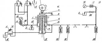
Hydraulic system of crank shears NA3218
Hydraulic shear pump NA3218
The purpose of the pump is to ensure the operation of sheet clamps by creating pressure in the system for each cutting cycle. In the assembled body of the NA3218 scissors, which includes a manifold 1, a tank 2 and a cylinder 3, there is a piston group consisting of two pistons 6 and 7, driven by a fist 4 rigidly fixed to the eccentric shaft of the scissors. Piston 6 with cylinder 3 forms a cavity P - low pressure, and piston 7 with piston 6 - a cavity of high pressure.
Spring 9, through lever 10, presses piston 6 to profiled cam 4, cavities P and channel 11 are connected to the clamp line.
When the eccentric shaft of the scissors is rotated, the fist 4 moves the piston 6 through the roller 5, while compressing the spring 9 with the lever 10.
Oil from cavity Q, as well as from the cavity through the open cavity of the spool 12, enters the main channel 11 and then into the cavities of the clamps, causing the clamp rods to move. Spool 12 is open until the clamps touch the sheet. Then the pressure in the hydraulic system increases sharply and causes the spool to close, which, overcoming the force of the spring 13, blocks the oil outlet into the main channel. At the same time, closing the spool ensures that cavity P through channel 14 communicates with the drain into cavity Z. The closing moment of spool 12, and therefore the amount of pressure in cavity P, is adjusted at the manufacturer. The operating pressure in the system is controlled by pressure gauge 16 and limited by safety valve 17 (ball type). The working pressure is adjusted depending on the thickness of the sheet being cut using screw 20.
After cutting, fist 4 releases piston 6, which spring 9 returns to its original position - the pressure in the system drops. Oil flows under the pistons, supplied by clamps from the return springs and from the tank through the check valve.
The hydraulic system is filled with oil at idle speed of the scissors with valve 18 open, for which screw 19 is screwed into the valve body. At the same time, observe the flow of oil from the cavities of the clamps into the pump tank. If there are no bubbles or foam in the leaking oil within 10-15 strokes of the slider, stop the scissors and unscrew screw 19, releasing the valve ball. The hydraulic system is full.
Guillotine shears – sheet length 2000 mm
| MODEL | MAXIMUM LENGTH OF SHEET, MM | MAXIMUM SHEET THICKNESS, MM | MAXIMUM LENGTH OF CUT STRIP AT STOP, MM | KNIFE STROKES PER MIN | DIMENSIONS, mm | WEIGHT, KG |
| NG-20M | 2000 | 20 | 1000 | 6 | 2870x2250x2350 | 9300 |
| H478 | 2000 | 18 | 1000 | 20 | 3150x2275x2350 | 11 000 |
| NA3122 | 2000 | 16 | 500 | 60 | 3325x1950x2375 | 8000 |
| NG-16 | 2000 | 16 | 500 | 3145x1920x2225 | 6900 | |
| NG-13 | 2000 | 13 | 500 | 3100x2000x2250 | 5600 | |
| NA3121 | 2000 | 12 | 500 | 40 | 3390x2300x2345 | 7500 |
| H3118 | 2000 | 6,3 | 900 | 55 | 3160x1930x2175 | 5100 |
| NK3418 | 2000 | 6,3 | 700 | 25 | 2780x2050x1510 | 4250 |
| NK3416 | 2000 | 4 | 700 | 25 | 2610x2050x1510 | 2870 |
| H3116 | 2000 | 4 | 450 | 40 | 2850x2050x1850 | 4500 |
| ND-3314G | 1600 | 2,5 | 700 | 34 | 2300x1570x1470 | 2000 |
| NG1250 | 1250 | 1 | 1550x1240x1070 | 380 |
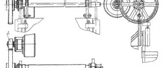
Design and principle of operation of crank shears NA3218 with an inclined knife
Crank shear frame NA3218 with inclined knife
The frame consists of two steel racks 1, connected at the top by a receiver 2 and a traverse 3; a table 4 rests on the traverse and the protrusions of the racks, to which a set of three knives 6 is attached with special screws 5. Longitudinal displacement of the knives during cutting is prevented by special stops 7.
Worm gearbox of crank shears NA3218 with inclined knife
In the cast housing of the crank shears NA3218, mounted on the right post of the frame, there is a worm gearbox for rotating the crankshaft of the shears, to which the worm wheel (1) of the gearbox is secured using keys.
In the cast housing of the scissors NA3218, mounted on the right post of the frame, there is a worm gearbox for rotating the crankshaft of the scissors, to which the worm wheel 1 of the gearbox is secured using keys.
A worm shaft 2 is fixed to the wheel 1, mounted in a housing on bearings that take up the axial and radial loads of the shaft 2. At the right end of the shaft on bearings mounted on a fixed axle 4, a flywheel 3 is mounted with a friction clutch-brake, the hub 5 of which is connected by splines to shaft 2.
The clutch-brake is activated as follows: compressed air through the air supply head 6, the holes of the shaft 2 enters the pneumatic chamber. The air moves the cylinder 7 and closes the rubbing surfaces of the driving 9 and intermediate 10 disks, overcoming the resistance of the spring 8. The driving disks, connected to the flywheel through pins, rotate and transmit rotational motion to the shaft 2. At the same time, the cylinder 7 opens the rubbing surfaces of the brake disk 11, which is motionless connected to the fixed flange 12, shaft 2 is released.
To supply electrical signals to turn off and turn on the clutch-brake, a non-contact sensor 13 is mounted on the gearbox cover, operating from movable disks 15 with cutouts connected to the crankshaft.
To register the lubricant level in the gearbox there is an oil indicator 16. The control panel 17 is attached to the housing for ease of use.
The rotation of the flywheel is perceived by V-belts from an electric motor 18 mounted on a bracket 19, which is adjusted vertically using bolts 14, after loosening them for the required belt tension.
Knife beam of crank shears NA3218 with inclined knife
The knife beam of the NA3218 scissors is a welded rigid structure of a slider 1 with a crankshaft 2 and connecting rods 3.
A set of knives 5 in the amount of three pieces, identical to the fixed knives on the frame, is attached to the lower edge of the slide with special screws. To prevent wear of the slider in the part due to cutting forces, the knives rest on spacers 6. The spacers are replaced to compensate for the size of the knives during regrinding.
The crankshaft 2, mounted in sliding bearings 7 and 8, enclosed in axle boxes mounted on the frame struts, is connected to the slider 1 by connecting rods 3, which contain sliding bearings 9, covering the eccentrics of the crankshaft and bearings 10, covering the axes 11. Axes 11 by the housings are firmly connected to the slider 1.
To connect the balancers, the slider brackets 1 have holes with sliding bearings 13. The crankshaft has additional supports 12, in the form of sliding half-bearings on the frame brackets, which reduces the bending of the shaft from cutting forces.
The direction of movement of the knife beam relative to the vertical of the stationary knives is 1°30', which allows the use of knives with mutually perpendicular sharpening planes.
Clamping beam for crank shears NA3218
It is a steel cross-beam 1, mounted on the front protrusions of the NA321 scissor frame struts and having special cutouts for securing the front ends of the frame brackets with additional crankshaft supports.
There are 12 clamps attached to the beam below, which keep the sheet being cut from moving during cutting. Each clamp consists of pistons with a pressure rod, sealed with rubber cuffs, a return spring, enclosed in a housing with a replaceable sleeve and connected to the longitudinal channel with holes sealed with rubber and steel rings.
Oil under pressure is supplied to the clamps through a channel.
On the right, a housing with valve 2 is attached to the pressure beam to release air from the hydraulic system when the shears are idling. Sealing of the housing joint is achieved with a rubber ring 3. The two leftmost clamps are brought closer together in case of cutting narrow strips. To adjust the gaps in the slider guides, there are 4 threaded bushings 4 with thrust spherical inserts 5, which achieve movement of the guide wedges 6. Clamping of the adjusted wedges is achieved with studs 7 and nuts 8 and 9.
Back stop of crank shears NA3218 with inclined knife
The back stop is a welded structure consisting of:
- 2 channels with screws inside;
- electric motor.
The back stop is attached to the blade beam from below.
The amount of movement of the rear stop is 630mm.
Control is carried out from the remote control.
The error of the back stop is up to 0.8mm
Crank shear balancers NA3218 with inclined knife
Scissor balancers NA3218 are used to facilitate the operation of the knife beam drive by balancing it. They are two pneumatic cylinders, the force of which overcomes the weight of the knife beam and ensures its constant contact with the bed guides for greater cutting accuracy. The lifting cavities of the cylinders are constantly connected to a receiver filled with compressed air at a certain pressure. The cylinders contain pistons. The lower forks of the rods are pivotally connected to the knife beam brackets using axles. Pistons and cylinder rods are sealed with cuffs.
Crank shear drive guard NA3218
The drive guard is a metal casing that covers the moving parts of the HA3218 scissors drive and has special cutouts for access to lubrication points and the flywheel in case it is turned by hand.
Fencing the cutting area of scissors NA3218
This is a metal grid rigidly attached to the knife beam, covering the danger zone of the HA3218 scissors.
Design
Each model of guillotine shears includes the following components:
- all-welded frame. Performs the function of a stable base to which all other nodes are attached;
- Desktop. Intended for placing sheet blanks;
- pressure beam. Provides strong fixation of the processed material;
- knife beam. It has a vertical feed type. The cutting angle is set according to the sheet thickness;
- drive unit. Can be hydraulic or crank-lever.
Purpose and areas of application
Scope of application – industrial, procurement shops of small-scale, medium-scale production. As a rule, sheet materials are used in the manufacture of body parts. That is why guillotine shears model H3118 can be found in the field of machine building, shipbuilding, and in procurement shops.
Purpose – cutting sheet materials to specified sizes. Processing is carried out exclusively in the transverse, longitudinal and straight directions along the thickness of the sheet. However, there are certain restrictions on how thick the sheet can be. The sheet should not be higher than 50 kgf/mm2.
Our offer
LLC SO "PRESSMASH" produces guillotine shears equipped with a hydraulic drive and CNC. The presence of software control allows you to quickly calculate the following parameters for each sheet:
- gap between blades;
- the angle at which the knife edge should be positioned;
- length of strip to be cut.
The calculation is made based on the entered data: sheet thickness and type of material. The hydraulic drive ensures rigid fixation of the workpiece with a pressure beam along its entire length, thereby guaranteeing high cutting accuracy. All guillotine shears of SO "PRESSMASH" LLC are equipped with steel blades. At the request of the customer it is possible to equip with additional devices.
To buy or find out the price of equipment, contact us by phone, request a call back or send an email to our email address. To receive a commercial offer, fill out the appropriate form on the website. You can first consult with our specialists by leaving them a message in the online chat.
crank sheet shears with inclined knife NA3218
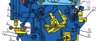
General view of crank shears NA 3218 with designation of components
List of components of scissors NA3218:
- NA3218-11-001 Bed
- NA3218-22-001 Gearbox
- NA3218-31-001 Knife beam NA3218
- NA3218-32-001 Pressure beam NA3218
- NA3218-34-001 Balancers
- NA3218-41-001 Pneumatic system
- NA3218-71-001 Drive guard
- NA3218-72-001 Fencing the cutting area
- NA3218-81-001 Lubrication system
- NA3218-83-001 Hydraulic pump
- NA3218-90-001 Electrical equipment
- NA3218-94-001 Lighting
- NA3218-15-001 Foundation
- NA3218-91-001 Control panel
- NA3218-92-001 Electric pedal
- NA3218-21-001 Side support 2 pcs
- NA3218-25-001 Back stop
Electrical equipment of guillotine crank shears NA-3218
The electrical equipment is located in the electrical cabinet. Controls and light signaling are located on the control panel.
The electrical equipment of the NA3218 scissors is made according to the electrical circuit diagram.
The following voltages are used in the circuit:
- 380V; 50Hz – power supply circuit for electric motors and transformers;
- 110V; 50Hz – power supply to relays, magnetic starters;
- 22V, 50Hz – power supply for alarm circuits;
- 22V, 50Hz – power supply for lighting circuits of the cutting area (when using an incandescent lamp) and local lighting;
- 24V, 00Hz – power supply for electromagnets of pneumatic valves, relays, BVK.
Connection and disconnection of guillotine shears NA3218 to the network is carried out by an input circuit breaker on the wall of the electrical cabinet. The remote control contains operating mode switches:
- SA1 – “Pedal” - single stroke - continuous stroke.
- SA2 – work – push – manual rotation
| Designation | Name | Purpose |
| M1 | Main engine | Drive of working mechanisms |
| M2 | Backgauge motor | Backgauge drive |
| M3 | Engine oil station | Oil station operation |
| RT1 | Thermal relay | Main motor overload protection |
| RT2 | Thermal relay | M2 overload protection |
| KM1 | Actuator | Starting the main motor under voltage, zero protection |
| KM2 | Actuator | Turning on the pneumatic coupling |
| KM3 | Actuator | Double stroke blocking and reverse |
| KM4, KM5 | Starters | Starting the rear support drive motor under voltage |
| KM6 | Actuator | Turning on the oil station |
| SA1 | Switch | Selecting operating modes |
| SA2 | Switch | Selecting operating modes |
| SA3 | Switch | Turning on the local lighting lamp |
| VD1 | Diode bridge | Rectifier |
| TV1 | Transformer | Power supply for control, alarm and lighting circuits |
| КV1 | Relay | Turning off the air clutch electromagnets at top dead center |
| YА1, YА2 | Electromagnets | Supply and removal of air pressure on the pneumatic coupling |
| SВ1 | STOP button | General stop |
| SВ2 | START button | Start M1 |
| SВ3 | START button | Turning on the pneumatic coupling |
| SВ4 | STOP button | "STOP" of continuous strokes |
| SВ7 | Pedal | Turning on the pneumatic coupling |
| SВ6 | START button | Switching on M2 “FORWARD” |
| SВ5 | START button | Turning on M2 “BACK” |
| SB8 | START button | Forced activation of M3 |
| SQ1 | Military-industrial complex | Hand protection on the line in the cutting area |
| SQ2-3 | Military-industrial complex | Checking the end positions of the back gauge |
| HL1-7 | Signal lamps | Control of operating modes |
| EL1-5 | Lighting lamp | Work area lighting |
| FU1-3 | Circuit breakers | Protection of control, alarm and lighting circuits from overloads |
Starting the main drive motor
- Turn on the OF1 circuit breaker in the control unit and the “Network” light signal lamp, HL1, turns on
- Set switch SA to the “Operation” position.
- By pressing the button SB2, the circuit of the coil KM1 of the magnetic starter is closed, which, with its block contacts, blocks the contacts of the button SB2, KM1, and powers the clutch control circuits. The magnetic starter KM1 uses power contacts to turn on the electric motor of the main drive M1 (1).
- The M1 electric motor can be turned off by pressing the SB1 – “General stop” button located on the remote control.
Single move
- Perform all operations to start the main electric motor and start it. Set switch SA2 to the “WORK” position.
- Switch SA1 moves to the “Pedal control” position.
- The knife beam, having made the “Down” move, returns to its original upper position.
- When the knife beam reaches the upper initial position, the cutouts in the screen disks are aligned with the working area of the BVK control device, which disables the shear clutch.
- If you press the pedal for a long time, there will be no restart; to restart, you must release the pedal and press again.
Continuous moves
- Switch SA1 moves to the “Pedal control” position.
- Turn on the lubrication system. Perform all operations to start the engine and start it.
- Set switch SA1 to the “Continuous stroke” position. Its contacts close and power the continuous stroke control circuits, and the HL5 lamp of the “continuous strokes” light signal turns on.
- Press the ST3 “Start” button on the control panel. The clutch takes a long time to engage. The command to disengage the clutch is given by pressing the button SВ4. The knife beam becomes in the upper extreme position.
Adjustment (Push)
The following modes are used in setup:
- "Push";
- "Manual rotation". (with the main electric motor turned off);
Switching on is done by button SВ3.
Manual rotation mode
- Set the SA2 mode switch to the “Manual rotation” position.
- The glow of the HL7 lamp is observed.
- The movement of the knife beam occurs only when the flywheel is turned manually
Adjusting the backgauge position
- This is done when adjusting the back stop to the size of the workpiece being cut, when working with the back stop.
- By pressing the SB5 and SB6 buttons, the M2 engine is turned on.
Protection
- Protection of electric motors and devices during short circuits is carried out by automatic switches.
- Protection of electric motors from overload of the main drive - a thermal relay, a back stop adjustment drive with an automatic switch.
- Control circuits are protected by fuses FU1-FU3/
- Zero protection is provided by contact group KM1.
- The open contact of the limit switch SQ1 switches off the main drive and clutch when the pressure beam guard is opened.
Signaling
- HL1 – network
- HL2 – engine on
- HL3 – single move
- HL4 – pedal operation
- HL5 – continuous strokes
- HL6 – “manual crank” mode
- HL7 – push mode
Adjustment of scissors NA3218
Regulation
gap between blades of scissors NA3218
The gap between the knives is adjusted after loosening the table mounting bolts. By turning the roller by the left tetrahedral shank, parallel movement of the table with fixed knives is achieved when controlled by the dials with which the shanks are equipped. After adjusting the gap, securely secure the table.
Recommended gap sizes for sheets of different thicknesses
| Thickness of cut sheets, mm | Up to 1.5 | 1,5-3 | 3-5 | 5-6,3 |
| Gap between knives when cutting steel mm | 0,05 | 0,1 | 0,17 | 0,21 |
| Gap between blades when cutting aluminum, copper and similar materials mm | 0,05 | 0,06 | 0,085 | 0,1 |
Adjusting the position of the worm wheel
When operating the NA3218 shears, only part of the worm wheel teeth, approximately 1/3, is subject to intense wear. By changing the position of the wheel relative to the crankshaft, less worn areas of the wheel teeth can be included in the work. For this purpose, splines are cut into the wheel hub. The wheel is driven through a hub having internal and external splines. The wheel, through a bushing having internal and external splines, is connected to the crankshaft by the bushing splines. Having removed this bushing, we will change the position of the wheel by turning the worm. Then put the bushing in place and secure it to the wheel hub.
Adjusting belt tension
The movement of the electric motor with the bracket is adjusted using adjusting horizontal bolts after loosening these bolts securing the bracket. The amount of belt tension can be determined by the deflection of each belt, which should be 15-20 mm from a force of 2-2.5 kg applied to the middle of the tense belt branch. After adjusting the tension of the under-engine bracket, secure it with the adjusting bolts.
Regulating compressed air pressure
Compressed air is supplied through the branch to the cavity of the receiver 4; the pressure in its cavity is adjusted using a regulator built into the branch. Pressure control is carried out using the regulator pressure gauge. For the cavities of the equalizers and clutch-brake, the pressure is adjusted within the range of 3.5-4 kgf/cm2. Increasing the pressure for the clutch violates its second purpose - as a torque protector
Regulating the pressure in the hydraulic pump lines
The pressure adjustment in the hydraulic pump is carried out in two objects: the control pressure of the pressure spools and the pressure in the clamp line. Pressure spools must open at a pressure in the clamp line that exceeds the pressure of their supply to the sheet being pressed. The dual system increases the reliability of the protection. The spools are set by the manufacturer to operate at a pressure in the hydraulic clamp line of 10-30 kgf/cm2 and no additional adjustment is required. After repair or washing, the spools are adjusted again to the specified pressure, for which one of the spools is removed, and the supply holes in the panel are plugged with a specially made plate. The remaining spool is adjusted with control using a pressure gauge, after which the removed spool is attached in its place and also adjusted. Then both spools are put in place and ready for use.
The pressure in the clamp line is regulated by the spring tension and is set by the manufacturer to 45 kgf/cm2. However, when cutting sheets less than 6.3 mm thick, it is recommended to reduce this pressure to facilitate pump operation, reduce wear on its parts and reduce oil heating.
Wearing parts of guillotine crank shears NA-3218
- plain bearings;
- knives;
- springs;
- textolite strips;
- set of rubber goods;
- friction linings;
- V-belts.