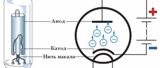
Rectifiers. How and why.
So, my dears, we have assembled our circuit and it’s time to check it, test it and enjoy this happiness. Next up is connecting the circuit to the power source. Let's get started. We won’t dwell on batteries, accumulators and other power supplies; we’ll move straight to mains power supplies. Here we will look at existing rectification schemes, how they work and what they can do. For experiments we will need single-phase (at home from an outlet) voltage and the corresponding parts. Three-phase rectifiers are used in industry, we will not consider them either. If you grow up to be an electrician, then please.
The power supply consists of several most important parts: Mains transformer - indicated in the diagram as similar to the one in the figure,
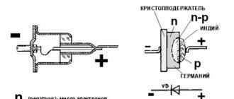
Rectifier - its designation may vary. The rectifier consists of one, two or four diodes, depending on which rectifier. Now we'll figure it out.
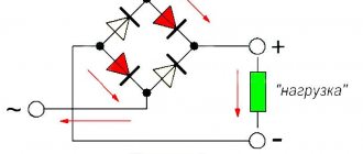
a) – a simple diode. b) – diode bridge. Consists of four diodes connected as in the figure. c) – the same diode bridge, only drawn simpler for brevity. The contact assignments are the same as for the bridge under letter b).
Filter capacitor. This thing is unchanged in both time and space, and is designated as follows:
There are many designations for a capacitor, as many as there are designation systems in the world. But in general they are all similar. Let's not get confused. And for clarity, let’s draw a load, denote it as Rl - load resistance. This is our scheme. We will also outline the contacts of the power source to which we will connect this load.
Next are a couple of postulates. – The output voltage is defined as Uconst = U*1.41. That is, if we have 10 volts of alternating voltage on the winding, then on the capacitor and on the load we will get 14.1 V. Like that. – Under load, the voltage sags a little, and how much depends on the design of the transformer, its power and the capacitance of the capacitor. – Rectifier diodes should be 1.5-2 times more current than required. For stock. If the diode is intended for installation on a radiator (with a nut or bolt hole), then at a current of more than 2-3A it must be installed on the radiator.
Let me also remind you what bipolar voltage is. If someone has forgotten. We take two batteries and connect them in series. The middle point, that is, the point where the batteries are connected, will be called the common point. It is popularly known as ground, ground, body, common wire. The bourgeoisie call it GND (ground), often referred to as 0V (zero volts). Voltmeters and oscilloscopes are connected to this wire; relative to it, input signals are supplied to the circuits and output signals are taken. That’s why its name is common wire. So, if we connect the tester with the black wire to this point and measure the voltage on the batteries, then the tester will show plus 1.5 volts on one battery, and minus 1.5 volts on the other. This voltage +/-1.5V is called bipolar. Both polarities, that is, plus and minus, must be equal. That is, +/-12, +/-36V, +/-50, etc. A sign of bipolar voltage is if three wires go from the circuit to the power supply (plus, common, minus). But this is not always the case - if we see that the circuit is powered by a voltage of +12 and -5, then such power is called two-level, but there will still be three wires to the power supply. Well, if as many as four voltages are supplied to the circuit, for example +/-15 and +/-36, then we will simply call this power supply - bipolar two-level.
Well, now to the point.
1. Bridge rectification circuit.
The most common scheme. Allows you to obtain unipolar voltage from one winding of the transformer. The circuit has minimal voltage ripple and is simple in design.
2. Half-wave circuit.
Just like the pavement, it prepares us a unipolar voltage from one winding of the transformer. The only difference is that this circuit has double the ripple compared to a bridge circuit, but one diode instead of four greatly simplifies the circuit. It is used for small load currents, and only with a transformer much larger than the load power, because such a rectifier causes one-sided magnetization reversal of the transformer.
3. Full-wave with midpoint.
Two diodes and two windings (or one winding with a midpoint) will supply us with a low-ripple voltage, plus we will get lower losses compared to a bridge circuit, because we have 2 diodes instead of four.
4. Bridge circuit of a bipolar rectifier.
For many, this is a sore subject. We have two windings (or one with a midpoint), we remove two identical voltages from them. They will be equal, the ripples will be small, since the circuit is a bridge circuit, the voltage on each capacitor is calculated as the voltage on each winding multiplied by the root of two - everything is as usual. A wire from the midpoint of the windings equalizes the voltage on the capacitors if the positive and negative loads are different.
5. Voltage doubling circuit.
These are two half-wave circuits, but with diodes connected in different ways.
It is used if we need to get double the voltage. The voltage on each capacitor will be determined by our formula, and the total voltage on them will be doubled. Like the half-wave circuit, this one also has large ripples. You can see a bipolar output in it - if the middle point of the capacitors is called ground, then it turns out like in the case of batteries, take a closer look. But you can’t get a lot of power out of such a circuit. Read also: Steering control of the front adapter for the walk-behind tractor
6. Obtaining different polarity voltage from two rectifiers.
It is not at all necessary that these are the same power supplies - they can be either different in voltage or different in power. For example, if our circuit consumes 1A at +12 volts, and 0.5A at -5 volts, then we need two power supplies - +12V 1A and -5V 0.5A. You can also connect two identical rectifiers to obtain a bipolar voltage, for example, to power an amplifier.
7. Parallel connection of identical rectifiers.
It gives us the same voltage, only with double the current. If we connect two rectifiers, then we will have a double increase in current, three - triple, etc.
Well, if everything is clear to you, my dears, then I’ll probably give you some homework. The formula for calculating the filter capacitance for a full-wave rectifier is:
For a half-wave rectifier, the formula is slightly different:
The two in the denominator is the number of rectification “cycles”. For a three-phase rectifier, the denominator will be three.
In all formulas, the variables are named as follows: Cf – capacitance of the filter capacitor, µF Po – output power, W U – output rectified voltage, V f – frequency of alternating voltage, Hz dU – ripple range, V
For reference - permissible ripple: Microphone amplifiers - 0.001. 0.01% Digital technology – ripple 0.1. 1% Power amplifiers - ripple of a loaded power supply 1. 10% depending on the quality of the amplifier.
These two formulas are valid for voltage rectifiers with a frequency of up to 30 kHz. At higher frequencies, electrolytic capacitors lose their efficiency, and the rectifier is designed a little differently. But that is another topic.
One of the most common current converters are rectifiers of alternating current into pulsating (constant in the direction of movement of the carriers, but variable in instantaneous magnitude) current. They have a very wide application. Conventionally, they can be divided into low-power rectifiers (up to several hundred watts and high-power rectifiers (kilowatts and more)).
Operating principle of the rectifier
The block diagram of the rectifier is shown below:
Its main part is the rectifying device B, formed from diodes combined in a special way. This is where the conversion of alternating current into pulsating direct current occurs. Alternating voltage is supplied to the rectifying device through the transformer Tr. In some cases, there may not be a transformer (if the voltage of the power network corresponds to that required for the operation of the rectifier). The transformer (if there is one) in most cases also has features in the connection of its windings. The pulsating current, as a rule, is not constant in value at every instant of time, and when it is necessary to have a smoother value than that obtained after the rectifying device, filters F are used. If necessary, the rectifier is supplemented with a voltage or current stabilizer St, which maintains them at a constant level if the power network parameters change for various reasons. The block diagram is completed by load H, which significantly affects the operation of the entire device and is therefore considered an integral part of the entire converter.
The rectifier itself is that part of it that is circled in the figure above with a dotted line and consists of a transformer and a rectifier device.
This subsection discusses low-power rectifiers, which are necessary to provide constant voltage to all kinds of devices in the areas of control, regulation, current amplifiers, low-power generators, and so on. As a rule, they are powered by single-phase alternating voltage 220 or 380 V with a frequency of 50 Hz.
Application benefits
The use of rectifiers by users is beneficial for the following reasons:
- The required basic parameters of the output voltage are set.
- The quality of the incoming power supply improves.
- A high efficiency of the equipment is ensured.
- Voltage ripple is reduced.
- The rectifier device can be used for a single-phase or three-phase network, depending on its structural diagram.
- The high efficiency of converting devices is combined with compactness and relatively low weight. Some models even provide remote control capabilities.
- The rectifier in most cases has negligible reactance.
Zero rectification circuit
It is advisable to consider the operating principle of the simplest single-phase current rectifier using the so-called zero circuit. Although it is now relatively rare (as discussed below), knowledge of the physical processes that occur in this circuit is very important for understanding further material.
The zero circuit looks like this:
Transformer Tr has two windings on the secondary side, connected in series in such a way that, relative to the midpoint a, the voltages at the free ends of windings b and c are equal in magnitude, but opposite in phase. The rectifier device is formed by two diodes D1 and D2, which are connected together at their cathodes, while each anode is connected to a corresponding winding. The load Zn is connected between the cathodes of the diodes and the point of the transformer.
Let's look at how pulsating voltage occurs across a load. First, we will consider the load to be purely active resistance, Zн=Rн. When the voltage in the windings changes according to a sinusoidal law, then during that half-cycle when a positive potential is applied to the anode of the diode, direct current will flow. Since the voltage across the diode is a fraction of a volt, we will neglect it. Then the entire positive half-wave of alternating voltage will be applied simply to the load Rн. When the voltage is applied negative to the anode, there will be no current (we will also neglect the small reverse current of the diode). Thus, only a positive half-wave of alternating voltage will reach the load during half the period. The second half of the period will be free of current.
The secondary windings are connected in antiphase, the load is common to both windings, thus, while current flows in one of them (for example, in the upper one), the other will be free from it and vice versa.
Read also: Electrical safety class of power tools table
Therefore, in the load, each half-cycle will be filled with a half-wave of alternating voltage:
And the rectified voltage Ud will have the form of identical half-waves, which are repeated with a period half as long as the period of the alternating voltage in the power supply network (2π radians). For generalization, which will be convenient, we will further assume that the period of change of the rectified voltage is less than 2π by m times and equals 2π/m (in our case m-2). If the load is an active resistance Rн, then the current in it id will follow the voltage curve.
The considered circuit will have the disadvantage that in the secondary windings, compared to the primary, there are significant current ripples, because these windings operate in turn. Since they are wound on one core, the magnetic flux in the latter will be variable, therefore in the primary winding the current will be variable, having both positive and negative half-waves. As you know from the electrical engineering course, the effective and average values of current or voltage are the same only for direct current. The greater the pulsation, the greater the effective value will be relative to the average. Therefore, the power on both sides of the transformer will not be the same. However, there is only one transformer, and the volume of iron for its core should be selected based on a single power value.
Therefore, we conditionally introduced the concept of typical power of a transformer, which is equal to the average of the powers of both sides:
Bridge circuit
This popular electronic rectifier belongs to the full-wave category. The bridge circuit is one of the most common.
With alternating voltage, the direction of the current changes according to a sinusoidal law. This happens twice during one cycle. At a frequency of 50 Hertz, the direction changes 100 times per second. As a result of the operation of the diode bridge, only positive voltage pulses will be received at the output.
The diagram below shows how current flows through the diode bridge for each half-cycle. It chooses the appropriate route depending on the sign of the voltage.
When the top terminal is positive, current flows to the wire leading to the positive DC output, selecting the top right leg of the diode bridge. If the voltage is negative, then current flows from the bottom terminal to the indicated wire. The other branch of the circuit works in a similar way.
When assembling such a rectifier, the polarity of the bridge must be taken into account. Otherwise, you may connect the capacitor incorrectly, which may damage it. To do this, just remember the following rule. At the point where the cathodes are facing, you need to connect the positive wire, and at the point where the anodes are facing, you need to connect the negative wire.
The voltage will be supplied to the output from the diode bridge in the form of a sequence of pulses of positive polarity. When it increases, the capacitor charges, and when it decreases, it releases charge, smoothing out the pulses. As a result, a constant voltage is generated at the output of the circuit.
A converter consisting of a diode bridge can be made independently from four radio components or use a ready-made one. In the latter case, it is a solid element with markings on each output necessary for correct connection.
Bridge rectifier or Graetz circuit
This drawback can be corrected by using a rectifying device in the form of a so-called bridge (Graetz circuit):
In this case, the first half-cycles will work, for example, diodes D2 and D4, and the second half-cycles - D1 and D3. At the load each time there will be a full half-wave of the secondary voltage:
The bridge circuit also has a less complex, lighter and cheaper transformer. As we will see later, it has several other advantages.
It is interesting that this circuit appeared historically earlier than the zero circuit, but was not widespread because, firstly, it had four diodes instead of two. However, the main thing was not their number, but the fact that during operation, every half cycle, the current passes through two series-connected diodes, onto which double voltage drops. At that time, there were no semiconductor diodes yet, and vacuum or mercury diodes had a significant voltage drop when direct current passed, which significantly reduced the efficiency. It turned out that a more complex neutral circuit transformer, but with one diode in the current rectification circle, is more economically profitable than a bridge circuit with double the number of diodes and double the energy consumption for them. And only the advent of relatively cheap semiconductor diodes with a very small forward voltage drop made it possible to turn to bridge circuits, which have now practically replaced the zero circuit (in this, if desired, one can see a manifestation of one of the dialectical laws - development in a spiral).
What is a rectifier
This device receives a sinusoidal signal at the input and converts it into a constant voltage of the required value. It is important to understand that the output result in most cases is not a smooth straight line. In fact, we are talking about a signal that is close to it. It is obtained as a result of pulse smoothing.
Typically, voltage rectification occurs in two stages. At the first, the incoming alternating current is converted so that it acquires the desired amplitude. Transformations are carried out using a transformer. At the second stage, voltage fluctuations are equalized.
The rectification process is based on the phenomenon of one-way conduction. In this case, current can pass in one direction, but not in the other. Previously, vacuum devices or synchronizing machines were used for this, but now such methods are not used. Semiconductor diodes are installed in modern rectifying devices.
Each such device consists of three blocks: a transformer, a rectifier and a smoothing circuit (filter). The first is designed to adjust the output voltage level. It uses alternating voltage at its input and output. The rectifier cuts off negative pulses and supplies only positive ones to the output.
Smoothing is usually done using a capacitor. When the voltage increases, a charge accumulates on its plates, and when it decreases, it is removed from them. Thus, sudden changes are smoothed out, making the output voltage acceptable for consuming equipment. The signal is not completely equalized, but it becomes suitable in its parameters for the electrical equipment used. The quality of the work performed is characterized by the rectification coefficient. Typically this is the ratio of the device's forward current to its reverse current. But such a calculation is acceptable for an ideal device. Thus, the rectification coefficient can reach several hundred thousand. The larger it is, the better the straightener does its job.
Rectifiers, which are based on semiconductor elements, are classified according to the following criteria:
- Output power (high, medium and low power).
- Power phase (single-phase, three-phase, polyphase).
- Type of valve control (controlled, uncontrolled).
- Type of load (active, active-inductive, active-capacitive).
The choice of device circuit depends on the load and the form of current consumption. In this case, it is necessary to take into account such parameters of rectifiers as:
- current;
- voltage;
- Power factor;
- output voltage ripple;
- efficiency.
Basic relations for a rectifier
Let us derive some important formulas that describe the processes that exist in this scheme. We will assume that the given values are the average voltage across the load Ud and the average current in it Id.
Average rectified voltage
Let's remember this expression for later. In our case m=2 and . Since Ud is considered given, then
Amplitude value of secondary voltage
From the previous expression we have:
Transformer ratio
This coefficient determines the ratio of the supply network to the voltage on the secondary side winding:
Effective value of the secondary winding current
The current of the secondary winding at the same time is the current in the load. Since the load is purely active and the current in it follows the shape of a pulsating voltage, then between its average value and its effective value there is the same relationship as for voltages, that is
Effective value of the primary winding current
The current in the primary winding repeats, taking into account n, the current of the secondary winding:
Transformer power
The powers of the primary and secondary sides of the transformer in this circuit are the same, therefore:
Rectified voltage ripple
The pulsating voltage consists of an average value Ud and an infinite number of harmonic components, the amplitudes of which can be determined using Fourier formulas. If the origin of coordinates is chosen as in the figure, then only cosine harmonics will be present in the harmonic composition (since the curve is symmetrical relative to the coordinate axis). The amplitude of the kth harmonic is determined by the formula:
Where: l – half-cycle π/m;
The first harmonic U(1)m will have the largest amplitude, so we determine only it, assuming that k=1:
Replacing we get:
The ratio of the first harmonic to the average value is called the ripple factor:
Let's remember this formula for the future, but now note that in our case, for m – 2, q – 2/3. These are large ripples - the amplitude of the first harmonic is 67% of the average value of the rectified voltage.
Average diode current
As we have already seen, the diodes work in turn - each of them conducts on average half of the total current that is in the load. Therefore, each of the diodes must be designed for current Iв = Id/2
Highest reverse voltage across diode
While diode B1 is conducting, it can be considered closed, and then the voltage of the secondary winding will be applied to diode B2 in the opposite direction. Therefore, each of the diodes must be designed for its amplitude value:
The full-wave rectifier is more common than the half-wave rectifier, this is due to the numerous advantages of such a circuit. To explain exactly what the advantage is, we should turn to the theoretical foundations of electrical engineering.
First of all, let's look at the difference between a full-wave rectifier and a half-wave rectifier; to do this, you need to understand the operating principle of each of them. Examples of circuits with oscillograms will give a clear idea of the advantages and disadvantages of these devices.
Half wave converter
Below is a typical diagram of such a device with a minimum of elements.
Read also: How to unscrew a spinning bolt
Scheme: the simplest converter
Designations:
- Tr – transformer;
- DV valve (diode);
- Cf – capacitance (plays the role of a smoothing filter);
- Rn – connected load.
Now let's look at the oscillogram at control points U1, U2 and Un.
Oscillogram taken at control points U1, U2 and Un
Explanation:
- control point U1 displays a diagram taken at the device input;
- U2 – diagram in front of the capacitive smoothing filter;
- Un – oscillogram at the load.
The timing diagram clearly shows that after the valve (diode), the rectified voltage is represented in the form of characteristic pulses consisting of positive half-cycles. When such a pulse occurs, the charge of the capacitive filter accumulates, which is discharged during the negative half-cycle, this allows the pulsations to be somewhat smoothed out.
The disadvantages of such a scheme are obvious - it is low efficiency, due to the high level of ripple. But despite this, devices of this type find their use in circuits with low current consumption.
Operating principle of a full-wave circuit
Let's consider two options for implementing a full-wave converter (rectifier): balanced and bridge. The diagram of the first is shown in the figure below.
The simplest uncontrolled balanced converter using two diodes using a transformer with a middle output
Elements used:
- Tr is a transformer that has two identical secondary windings (or one with a tap in the middle);
- DV1 and DV2 – valves (diodes);
- Cf – capacitive filter;
- Rn – load resistance.
For clarity, let us immediately present an oscillogram at control points.
Diagram of a balanced type device
- U1 – input oscillogram;
- U2 – graph in front of the capacitive filter;
- Un – diagram at the device output.
This circuit is two combined half-wave converters, that is, two separate sources account for one common load. The result of the operation of such a device is clearly demonstrated by graph U2. It shows that both half-cycles are used in the process, which gives these converters their name.
The oscillogram clearly demonstrates the advantages of such a device, namely the following facts:
- the ripple frequency at the device output doubles;
- reducing the “dips” between pulses allows the use of a smaller filter capacitance;
- A push-pull converter has greater efficiency than a half-wave converter.
Now let's look at the bridge type, it is shown in the figure below.
Diagram: Example of using a diode bridge
The oscillogram of a bridge type device is practically no different from a balanced one, so there is no point in presenting it. The main advantage of this scheme is that there is no need to use a more complex transformer.
Video: Full-wave rectifier bridge
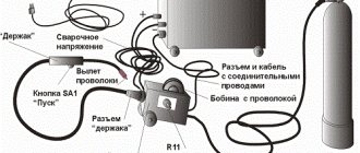
Converters that use a semiconductor diode bridge are widely used both in electrical engineering (for example, in welding machines, where the rated current can reach up to 500 amperes) and in radio electronics, as a source for low-current circuits.
Note that in addition to semiconductor diodes, you can also use vacuum diodes - kenotrons (an example of a circuit diagram of such a device is shown below).
Scheme: converter based on a 6Ts4P two-anode kenotron
Actually, the presented circuit is a classic implementation of a full-wave balanced converter. Today, vacuum diodes are practically not used; they have been replaced by semiconductor analogues.
History of creation
In 1873, British scientist Frederick Guthrie proposed a rectification circuit based on the use of vacuum diodes. The following year, 1874, Karl Ferdinand Braun from Germany invented the solid-state point rectifier.
In 1904, John Flemming created a high-quality tube diode, which later served as the basis for the creation of the devices in question. 2 years later, a crystal detector was invented. In the thirties, active research was carried out on the effects that occurred at the interface between crystals and metal parts. Based on them, the phenomenon of pn transition was discovered in 1939. At the same time, the influence of certain impurities on the type of conductivity (electronic or hole) was revealed.
The rectifier bridge in the form in which it is now known was created by the Polish electrical engineer Karol Pollak. Later, but independently of him, the same discovery was made by Leo Graetz. Sometimes in technical literature the name given in honor of the latter is used - the Graetz circuit.
In conclusion, it should be said that the principle of constructing a rectifying device can be used in very different ways. But any of them provides an output voltage that can only be called constant conditionally. The rectifier produces a unidirectional pulsating voltage. In most cases, it needs to be smoothed with filters.
How to organize bipolar power supply
By combining a balanced circuit and a bridge circuit, you can get a converter that will provide bipolar power at the output with a common (zero) point. Moreover, for one it will be negative, and for the other it will be positive. Such devices are widely used in power supplies for digital radio technology.
Diagram: example of a converter with bipolar output
Multiphase rectifiers
Typically, the electrical network has single-phase or three-phase electricity. However, in an industry such as electrical engineering, multiphase voltage is also used. We are talking about a situation where the number of phases is more than three. In this case, rectifiers are used, which are called N-phase.
They work with them in the same way as with three-phase ones. Almost always, bridge circuits in the required quantity are used for this purpose. The classification of rectifiers for this case includes devices that are separate for each phase, connected by a ring or star, and also in series.
How to implement voltage doubling
Below is a circuit that allows you to obtain a voltage at the output of the device that is twice as high as the original one.
Voltage doubling circuit
It is typical for such a device that two capacitors are charged in different half-cycles, and since they are located in series, then, as a result, the total voltage at “Rn” will be twice as high as at the input.
In a converter with such a multiplier, transformers with a lower secondary winding voltage can be used.
Using Op Amps
As is known, the current-voltage characteristic of diodes is nonlinear; by creating a single-phase precision (high-precision) full-wave rectifier on an op-amp chip, the error can be significantly reduced. In addition, it is possible to create a converter that allows you to stabilize the current on the load. An example diagram of such a device is shown below.
Circuit: a simple op-amp stabilizer
The figure shows a simple current stabilizer. The op amp used in it is a voltage controlled source. This implementation makes it possible to ensure that the current at the output of the converter does not depend on the voltage loss across the load Rн and the diode bridge D1-D4.
If voltage stabilization is required, the converter circuit can be slightly complicated by adding a zener diode to it. It is connected in parallel to the smoothing capacitance.
Briefly about controlled converters
It is often necessary to control the voltage at the output of the converter without changing the input. For this purpose, the most optimal would be to use controlled valves; an example of such an implementation is shown below.
Simple thyristor converter (on controlled valves)
Half wave rectifier
The rectifier circuit with a capacitor is also considered one of the simplest. It looks like this:
As can be seen in the diagram, an alternating electric current rectifier with a capacitor is also equipped with a transformer that allows it to obtain the desired voltage. At this stage it remains variable, but changes amplitude. The rectifying action is based on the operation of a diode and a capacitor. Only the positive half-cycles of the sinusoid reach the capacitor plates, since the negative ones do not pass through the diode.
The top graph shows the sine wave of voltage entering the rectifier in the diagram shown. The lower one shows what this voltage will be as a result of passing through the diode.
The charge on the capacitor plates increases with increasing voltage. When it decreases to zero, it begins to drain, compensating for the jumps. The output receives a constant voltage. The circuit uses an electrolytic capacitor with a large capacity for this purpose. It is believed that the best converters for household equipment should have a capacity of at least 2200 microfarads.
Three phase rectifier
We looked at various implementations of single-phase full-wave converters, but similar devices are also used for three-phase sources. Below, as an example, a device created according to Larionov’s scheme is shown.
An example of the implementation of a Larionov circuit Oscillogram at the output of a Larionov circuit
As the graph above shows, the implementation of a bridge circuit between pairs of phases allows for minor ripples to be obtained at the output. Thanks to this, the filter capacity can be significantly reduced, or even dispensed with.
Half-wave three-phase rectifier
Such electrical devices receive signals from each of the three phases and from zero. The diagram looks like this:
Additionally, a capacitor is used for smoothing. A similar method is used in a single-phase rectifier, but in a three-phase rectifier the smoothing is better due to the phase shift relative to each other.
Design
Calculating even a simple full-wave converter is not an easy task. It can be significantly simplified using special software. We recommend choosing the Electronics Workbench program, which allows you to perform schematic modeling of analog and digital electrical devices.
By simulating a full-wave rectifier in this program, you can get a clear idea of the principle of its operation. Built-in formulas allow you to calculate the maximum reverse voltage for diodes, the optimal capacity of the quenching capacitor, etc.