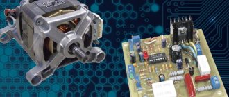
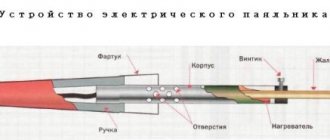
To perform various electrical work and assemble electronic circuits, a tool such as an electric soldering iron is often used. Its simplest type, which can be purchased at any hardware store, usually has a basic design.
It includes a heating element, a tip, a handle, usually wooden, and a power cable or cord. In some versions, the soldering iron can be equipped with several replaceable tips.
The power of such a soldering iron is fixed, most often 40 or 60 watts. But it is more convenient to use a tool with the ability to adjust power. Such models are also produced, although they are more expensive.
Switches and Dimmers
The simplest temperature control is used in soldering irons with a switch that allows only two positions, and, accordingly, two temperature values.
At the minimum value, the soldering iron mounted on the stand simply maintains the tip in a heated state, and when you press a key or button, the tip heats up to the maximum temperature at which soldering is performed.
Obviously, of the advantages described above, such a soldering iron only has the ability to save energy. The main task of adjustment - the production of high-quality and safe installation of components - remains impossible.
The second type of adjustable soldering irons is dimmable. Their design involves inserting a dimmer into the break in the power cable - a device that limits the power consumption of the soldering iron.
In this case, it really becomes possible to adjust the temperature of the tip, but this is done due to a voltage drop in the dimmer.
Accordingly, there can be no talk of any cost-effectiveness of such a scheme. But the price of such devices is quite low and can play a decisive role in the choice.
On a microcontroller
In the case when the performer is completely confident in his abilities, he can take on the production of a thermal stabilizer for a soldering iron running on a microcontroller.
This version of the power regulator is made in the form of a full-fledged soldering station, which has two working outputs with voltages of 12 and 220 Volts.
The first of them has a fixed value and is intended to power miniature low-current soldering irons. This part of the device is assembled using a conventional transformer circuit, which, due to its simplicity, can be ignored.
The second output of a self-assembled regulator for a soldering iron has an alternating voltage, the amplitude of which can vary in the range from 0 to 220 Volts.
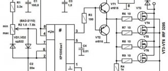
The diagram of this part of the regulator, combined with a PIC16F628A type controller and a digital output voltage indicator, is also shown in the photo.
For safe operation of equipment with two different output voltages, a homemade regulator must have sockets of different design (incompatible with each other).
Such forethought eliminates the possibility of errors when connecting soldering irons designed for different voltages.
The power part of such a circuit is made using a VT 136 600 triac, and the power in the load is adjusted using a push-button switch with ten positions.
By switching the push-button regulator, you can change the power level in the load, indicated by numbers from 0 to 9 (these values are displayed on the display of the indicator built into the device).
As an example of such a regulator, assembled according to a circuit with an SMT32 controller, we can consider a station designed to connect soldering irons with T12 brand tips.
This industrial prototype of a device that controls the heating mode of a soldering iron connected to it is capable of adjusting the temperature of the tip in the range from 9 to 99 degrees.
Copper fixtures
The structure is made of copper wire twisted in a spiral pattern. Copper is capable of transmitting low current produced by small transformers. Adjustable heating components are equipped with a temperature sensor, which is responsible for controlling the tip. The thermocouple is installed on the working tip, which allows you to adjust the temperature level to the required state. The copper spiral does not pass electric current through itself, the performance of the unit stops, or the load indicator changes. Types of copper heaters:
- with wire wound around the body, preventing voltage from reaching the tip;
- The insulated structure avoids heat loss when using the device.
Homemade thermostat
The quality of copper depends on performance; adding additives in order to save money by the manufacturer can significantly reduce the service life and damage the parts being repaired.
Origin story
A soldering iron is a tool designed to transfer heat to a material upon contact with it. Its direct purpose is to create a permanent connection by melting solder.
Until the beginning of the 20th century, there were two types of soldering devices: gas and copper. In 1921, German inventor Ernst Sachs invented and registered a patent for a soldering iron, which was heated by electric current. In 1941, Karl Weller patented a transformer-type instrument shaped like a pistol. By passing current through its tip, it quickly heated up.
Twenty years later, the same inventor proposed using a thermocouple in a soldering iron to control the heating temperature. The design included two metal plates pressed together with different thermal expansion. Since the mid-60s, due to the development of semiconductor technologies, soldering tools began to be produced in pulse and induction types.
Types of regulators
Devices for connecting various types of radio components have several types of characteristics. Soldering stations with heat and load adjustments are produced by the manufacturer with different parameter settings. Main varieties:
- Changing the voltage and power of the node is possible using a triac. This modification is most common when using heating components in radio engineering.
- Thyristor type adjusting element.
- Modification to increase the performance of the device allows you to change the output force to the required values.
- The indication makes it possible to recognize in which mode the heating is being carried out.
- Low-voltage controllers are used in designs designed to operate with a voltage of no more than 36 Volts.
https://youtube.com/watch?v=et60fwS8w5E
You can probably make components that have adjustable temperature volumes with your own hands. A simple structure without interference is used, which makes it possible to extend the service life of the heating element. The galvanic component is considered reliable; its versatility allows the design to be used with various modifications and models.
Circuit options depending on the power limiter
The power regulator can be assembled according to different schemes. The main differences lie in the semiconductor part, the device that will regulate the flow of current. This could be a thyristor or triac. For more precise control of the operation of a thyristor or triac, you can add a microcontroller to the circuit.
You can make a simple regulator with a diode and a switch - in order to leave the soldering iron in working condition for some (possibly long) time, without allowing it to cool down or overheat. The remaining controls make it possible to set the temperature of the soldering iron tip more smoothly - to suit various needs. Assembling the device according to any of the schemes is done in a similar way. The photographs and videos provide examples of how you can assemble a power regulator for a soldering iron with your own hands. Based on them, you can make a device with the variations you personally need and according to your own design.
A thyristor is a kind of electronic key. Passes current in only one direction. Unlike a diode, a thyristor has 3 outputs - a control electrode, an anode and a cathode. The thyristor opens by applying a pulse to the electrode. It closes when the direction changes or the current flowing through it stops.
Thyristor, its main components and display on diagrams
A triac , or triac, is a type of thyristor, but unlike this device, it is double-sided and conducts current in both directions. It is essentially two thyristors connected together.
Triac or triac. Main parts, principle of operation and method of display in diagrams. A1 and A2 - power electrodes, G - control gate
The power regulator circuit for a soldering iron, depending on its capabilities, includes the following radio components.
Resistor - serves to convert voltage into current and vice versa. Capacitor - the main role of this device is that it stops conducting current as soon as it is discharged. And it begins to conduct again - as the charge reaches the required value. In regulator circuits, the capacitor is used to turn off the thyristor. A diode is a semiconductor, an element that passes current in the forward direction and does not pass in the reverse direction. A subtype of diode - a zener diode - is used in devices for voltage stabilization. A microcontroller is a microcircuit that provides electronic control of a device. There are varying degrees of difficulty.
Diodes do not conduct current in the opposite direction
This is how a diode is designated in diagrams
Zener diodes are used to stabilize voltage
The capacitor is mainly used to turn off the thyristor
Appearance of the resistor and method of display on the diagram
The microcontroller allows software control of the device
Circuit with switch and diode
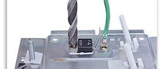
This type of regulator is the easiest to assemble, with the fewest parts. It can be collected without payment, by weight. The switch (button) closes the circuit - all voltage is supplied to the soldering iron, opens it - the voltage drops, and so does the temperature of the tip. The soldering iron remains heated - this method is good for standby mode. A rectifier diode rated for a current of 1 Ampere is suitable.
The easiest regulator to install
Assembling a two-stage regulator on weight
- Prepare parts and tools: diode (1N4007), switch with button, cable with plug (this can be a soldering iron cable or an extension cord - if you are afraid of ruining the soldering iron), wires, flux, solder, soldering iron, knife.
- Strip and then tin the wires.
- Tin the diode. Solder the wires to the diode. Remove excess ends of the diode. Put on heat-shrinkable tubes and apply heat. You can also use an electrically insulating tube - cambric. Prepare a cable with a plug in the place where it will be more convenient to mount the switch. Cut the insulation, cut one of the wires inside. Leave part of the insulation and the second wire intact. Strip the ends of the cut wire.
- Place the diode inside the switch: the minus of the diode is towards the plug, the plus is towards the switch.
- Twist the ends of the cut wire and the wires connected to the diode. The diode must be inside the gap. The wires can be soldered. Connect to terminals, tighten screws. Assemble the switch.
Regulator with switch and diode - step by step and clearly
Thyristor regulator
A regulator with a power limiter - a thyristor - allows you to smoothly set the temperature of the soldering iron from 50 to 100%. In order to expand this scale (from zero to 100%), you need to add a diode bridge to the circuit. The assembly of regulators on both a thyristor and a triac is done in a similar way. The method can be applied to any device of this type.
An example of mounting a thyristor regulator on a board
Assembling a thyristor (triac) regulator on a printed circuit board
- Make a wiring diagram - outline a convenient location of all the parts on the board. If the board is purchased, the wiring diagram is included in the kit.
- Prepare parts and tools: printed circuit board (it must be made in advance according to the diagram or purchased), radio components - see the specification for the diagram, wire cutters, knife, wires, flux, solder, soldering iron.
- Place the parts on the board according to the wiring diagram.
- Use wire cutters to cut off the excess ends of the parts.
- Lubricate with flux and solder each part - first resistors with capacitors, then diodes, transistors, thyristor (triac), dinistor.
- Prepare the housing for assembly.
- Strip and tin the wires, solder them to the board according to the wiring diagram, and install the board into the case. Insulate the connection points of the wires.
- Check the regulator - connect it to an incandescent lamp.
- Assemble the device.
Circuit with low-power thyristor
A low-power thyristor is inexpensive and takes up little space. Its peculiarity is increased sensitivity. To control it, a variable resistor and capacitor are used. Suitable for devices with a power of no more than 40 W.
This regulator does not require additional cooling
Specification
| Name | Designation | Type/Denomination |
| Thyristor | VS2 | KU101E |
| Resistor | R6 | SP-04/47K |
| Resistor | R4 | SP-04/47K |
| Capacitor | C2 | 22 mf |
| Diode | VD4 | KD209 |
| Diode | VD5 | KD209 |
| Indicator | VD6 |
Circuit with a powerful thyristor
The thyristor is controlled by two transistors. The power level is controlled by resistor R2. The regulator assembled according to this scheme is designed for a load of up to 100 W.
The regulator is optimal for loads up to 100 W
Specification
| Name | Designation | Type/Denomination |
| Capacitor | C1 | 0.1 µF |
| Transistor | VT1 | KT315B |
| Transistor | VT2 | KT361B |
| Resistor | R1 | 3.3 kOhm |
| Variable resistor | R2 | 100 kOhm |
| Resistor | R3 | 2.2 kOhm |
| Resistor | R4 | 2.2 kOhm |
| Resistor | R5 | 30 kOhm |
| Resistor | R6 | 100 kOhm |
| Thyristor | VS1 | KU202N |
| Zener diode | VD1 | D814V |
| Rectifier diode | VD2 | 1N4004 or KD105V |
Assembling a thyristor regulator according to the above diagram into a housing - visually
https://youtube.com/watch?v=4DG4_w2fe4E
Assembly and testing of a thyristor regulator (review of parts, installation features)
Circuit with thyristor and diode bridge
This device allows you to adjust the power from zero to 100%. The circuit uses a minimum of parts.
On the right is a voltage conversion diagram
Specification
| Name | Designation | Type / Denomination |
| Resistor | R1 | 42 kOhm |
| Resistor | R2 | 2.4 kOhm |
| Capacitor | C1 | 10 μ x 50 V |
| Diodes | VD1-VD4 | KD209 |
| Thyristor | VS1 | KU202N |
Triac regulator
Triac-based regulator circuit with a small number of radio components. Allows you to adjust power from zero to 100%. The capacitor and resistor will ensure the smooth operation of the triac - it will open even at low power.
An LED is used as an indicator in this power regulator.
| Name | Designation | Type/Denomination |
| Capacitor | C1 | 0.1 µF |
| Resistor | R1 | 4.7 kOhm |
| Resistor | VR1 | 500 kOhm |
| Dinistor | DIAC | DB3 |
| Triac | TRIAC | BT136–600E |
| Diode | D1 | 1N4148/16 B |
| Light-emitting diode | LED |
Assembling a triac regulator according to the given diagram step by step
Triac regulator with diode bridge
The circuit of such a regulator is not very complicated. At the same time, the load power can be varied over a fairly wide range. With a power of more than 60 W, it is better to place a triac on a radiator. At lower power, cooling is not needed. The assembly method is the same as in the case of a conventional triac regulator.
With a lower load power, the triac can be taken weaker
Example of mounting a regulator on a triac with a diode bridge on a printed circuit board
Regulator with triac - sample installation in a housing
Power regulator with triac on a microcontroller
The microcontroller allows you to accurately set and display the power level, and ensure automatic shutdown of the regulator if it is not operated for a long time. The installation method of such a regulator does not differ significantly from the installation of any triac regulator. It is soldered onto a printed circuit board, which is pre-fabricated. It is very important to install the correct firmware.
Such a regulator can replace a soldering station
Specification
| Name | Designation | Type/Denomination |
| Capacitor | C1 | 0.47 µF |
| Capacitor | C2 | 1000 pF |
| Capacitor | C3 | 220 V x 6.3 uF |
| Resistor | R1 | 22 kOhm |
| Resistor | R2 | 22 kOhm |
| Resistor | R3 | 1 kOhm |
| Resistor | R4 | 1 kOhm |
| Resistor | R5 | 100 Ohm |
| Resistor | R6 | 47 Ohm |
| Resistor | R7 | 1 MOhm |
| Resistor | R8 | 430 kOhm |
| Resistor | R9 | 75 Ohm |
| Triac | VS1 | BT136–600E |
| Zener diode | VD2 | 1N4733A (5.1v) |
| Diode | VD1 | 1N4007 |
| Microcontroller | DD1 | PIC 16F628 |
| Indicator | HG1 | ALS333B |
Types of soldering irons with temperature control
All modern devices, used as individual power tools and as part of soldering stations, depending on the type of heating element and method of heating the tip, are divided into pulsed, devices with nichrome and ceramic heaters.
Pulse soldering iron
Pulse soldering gun
This soldering iron is a device that operates on mains power, reducing the mains voltage but increasing the frequency of the current. This device does not work all the time, only when you press a button on the handle. Thanks to this, it is more economical than analogues of other types, and allows soldering of very small and delicate radio components.
With nichrome heater
The classic nichrome heating element of such a device is a metal tube with fiberglass, mica and numerous turns of thin nichrome wire wound around it. When heated, the wire, which has high resistance, heats up the tube with the copper tip inserted into it.
With ceramic heater
Soldering iron with ceramic heater
In such devices, the tip is placed on a tubular ceramic heating element, which has electrical conductivity and high resistance. When current passes, this ceramic tube heats up almost instantly, providing the fastest possible heating of the tip installed on it.
How does a soldering iron controller function?
There are a huge number of device diagrams for adjusting the heating of a soldering station. However, they all work on the same principle, which is to increase or decrease the input power. In rare cases, one or another regulator for a soldering iron may differ in the following characteristics:
- type of electronic circuit used;
- installed measuring element to determine power;
- number of power settings.
Regardless of the above differences, these devices will in any case be a regular switch for power regulation.
DIY soldering iron power regulator: proven working circuits (6 pcs)
Not everyone likes to buy unknown things. And some people find it more pleasant to make a soldering iron power regulator with their own hands, because this is also experience. Most circuits are assembled using triacs and thyristors; now they are easier to find than transistors. They are also easier to work with, since they are either open or closed, which allows you to make circuits simpler.
Choose any case
Simple thyristor circuits
When choosing a power regulator circuit for a soldering iron, two things are important: power and parts availability. The soldering iron power regulator presented below is assembled using widely used parts that are not a problem to find. The maximum current is 10 A, which is more than enough to perform any kind of work and for soldering irons with a power of up to 100 W. The thyristor in this circuit is used KU202n
Pay attention to the bridge connection. There are many circuits with connection errors
This option is working. Tested more than once.
Temperature controller circuit for a soldering iron using a thyristor
When assembling the circuit, be sure to place the thyristor on the radiator; the larger it is, the better. The circuit is simple, but when it is turned on, it creates interference. You can’t listen to the radio nearby, and to remove interference, we connect a 200 pF capacitor in parallel with the load, and a choke in series. The choke parameters are selected depending on the regulated load, but since soldering irons are usually no more than 80-100 W, the choke can be made at 100 W. To do this, you will need a ferrite ring with an outer diameter of 20 mm, on which about 100 turns are wound with a wire with a cross-section of 0.4 mm².
Another drawback of the diagram translated above is that the soldering iron “itches” noticeably. Sometimes you can put up with this, sometimes you can’t. To eliminate this phenomenon, you can select the parameters of capacitor C1 so that when the variable resistor is set to maximum, the connected lamp barely glows.
On other elements but also without interference
The above regulator can be used for any load. Let's give another analogue, but using a different element base. You can regulate not only the power/temperature of the soldering iron, but also any other load with a small inductive component.
A modified circuit for regulating the power of a soldering iron and any other load with the ripple effect eliminated
There is pulsation here, but its frequency is high and it will not be perceived by our vision. So it can be used not only as a dimmer for a soldering iron, but also to regulate the light from a regular incandescent lamp. Is a diode bridge needed to regulate the heating power of a soldering iron? It won't hurt, but it's not necessary.
On a thyristor with high sensitivity
This circuit allows you to smoothly change the temperature of the soldering iron from 50% to 100%. There are two indicators - power and power. The power presence LED always lights up when turned on, but at 75% power the glow is brighter. The power indicator changes the intensity of the glow depending on the operating mode.
Popular articles Women's denim windbreaker
Power regulator for soldering iron without interference
In order for the regulator to fit into the case of a mobile phone charger, resistances are used of SMD type (1206). All resistors are installed on the board, except for R 10. Some can be composite (we assemble the required value from series-connected resistors).
For normal operation of the circuit, a sensitive thyristor (with a low control current) and a low state holding current (about 1 mA) is required. For example, KT503 (designed for voltage 400 V, control current 1 mA). The rest of the element base is indicated in the diagram.
If assembled, but the voltage is not adjustable
If the assembled regulator does not regulate anything - the temperature of the soldering iron does not change - the problem is in the thyristor. The scheme seems to be working, but nothing happens. The reason is a thyristor with low sensitivity. The currents flowing in the circuit are not sufficient to open. In this case, it is worth installing an analogue with higher sensitivity (lower control currents).
One of the housing options in which you can hide a homemade power regulator for a soldering iron
The regulator may still work, but the soldering iron begins to “itch.” This problem is solved by installing a choke at the output (in front of the soldering iron). The capacity must be selected - it depends on the soldering iron. The second solution is an analog control circuit, and this is a different circuit.
Well, if you have problems with operation, look for either faulty parts or incorrectly selected components. This is usually the problem.
Mounting options
Power regulator assembly diagrams can be either simple or complex.
You will need:
- Dimmer box;
- Printed circuit board;
- Radio components for circuit assembly;
- Soldering iron;
- Solder;
- Flux;
- Tweezers.
The case can be made of plastic by cutting out blanks and gluing the box, or matched to the size of the board using an old charger, tee, single or double external socket, etc.
It is important that the entire microcircuit fits in it and that the device is comfortable to operate. The selection of the housing depends on both the power and the tasks of the voltage regulator.
If the dimmer is made for a soldering iron, then it can be mounted in a pre-purchased soldering iron stand. When you need to regulate the power of an incandescent lamp or the rotation speed of a fan, it must be placed so that it is convenient to use. It is better to install it in the device case when there is space inside it, or rigidly attach it to it.
Soldering iron with adjustable tip temperature: diagrams, types, application – Turner
To perform various electrical work and assemble electronic circuits, a tool such as an electric soldering iron is often used. Its simplest type, which can be purchased at any hardware store, usually has a basic design.
It includes a heating element, a tip, a handle, usually wooden, and a power cable or cord. In some versions, the soldering iron can be equipped with several replaceable tips.
The power of such a soldering iron is fixed, most often 40 or 60 watts. But it is more convenient to use a tool with the ability to adjust power. Such models are also produced, although they are more expensive.
DIY power regulator for a soldering iron - diagrams and installation options
There are many models of soldering irons in stores - from cheap Chinese ones to expensive ones with a built-in temperature controller; they even sell soldering stations.
Another thing is, is the same station needed if such work needs to be done once a year, or even less often? It's easier to buy an inexpensive soldering iron. And some people still have simple but reliable Soviet instruments at home. A soldering iron that is not equipped with additional functionality heats up as long as the plug is plugged in.
And when turned off, it cools down quickly. An overheated soldering iron can ruin the work: it becomes impossible to solder anything firmly, the flux quickly evaporates, the tip oxidizes and the solder rolls off it.
To make work more comfortable, you can assemble a power regulator with your own hands, which will limit the voltage and thereby prevent the soldering iron tip from overheating.
Construction and details
Many people are interested in what the design of such a regulator might be. This device can be external, in the form of a small separate block. Sometimes there are more compact designs that are built into a soldering station or into a socket housing.
The main parts of the soldering iron power regulator are resistors. Their power must be at least 0.125 W. If the device has R5, its power is from 2 W.
Additional Information! You may have to select a different part rating so that the supply voltage does not drop below 11 V.
DIY device design
As follows from examination of the circuit, it consists of a power section, which should be mounted using surface-mounted installation, and a control circuit on a printed circuit board. By the way, they can solder the board at Solderpoint.ru.
Creating a PCB involves making a design of the board. For this purpose, the so-called LUT, which means laser-iron technology, is usually used in everyday conditions. The PCB manufacturing method includes the following steps:
- creating a drawing;
- transferring the design to the board blank;
- etching;
- cleaning;
- drilling holes;
- tinning of conductors.
To create an image of a board, the Sprint Layout program is most often used. After receiving the design using a laser printer, it is transferred to the foil getinax using a heated iron. Then the excess foil is etched using ferric chloride and the pattern is cleaned. Holes are drilled in the right places and the conductors are tinning. The elements of the control circuit are placed on the board and they are soldered (there are certain recommendations on how to solder correctly with a soldering iron).
Assembling the power part of the circuit includes connecting resistors R5, R6 and diode VD2 to the thyristor.
The last stage of assembly is placing the power section and control circuit board in the housing. The order of placement in the housing depends on its type.
Since the dimensions of the power regulator elements on a triac are small and there are few of them, you can use, for example, a plastic socket as a housing. The largest place there is occupied by a variable adjustment resistor and a powerful thyristor. However, as experience shows, all the elements of the circuit, together with the printed circuit board, fit into such a housing.
Tools and materials
Despite the simplicity of the design, the triac regulator is a radio-electronic circuit. To manufacture such a device, you will need tools for machining metal and plastic. When installing electronics, you will have to use an existing soldering iron. Of course, to assemble even the simplest regulator, the master must have some knowledge and skills in the manufacture of radio structures.
First of all, having decided on your needs and plans, purchase the necessary electronic components from the list. The key and most expensive design element is the triac.
This small part must work reliably when connecting a load of the planned power, so it is better to buy a more expensive part with some power reserve.
The regulator circuits are so similar that a sales consultant will help you select the parts right in the radio store . It’s even easier to find a ready-made kit for assembly on the website of a radio parts store. It will already contain all the necessary components and assembly instructions.
An equally important detail is the body of the future regulator. It should be compact, but contain all the necessary elements. The convenience of connecting the consumer is of great importance. As a housing, you can use a ready-made electrical box with a built-in electrical outlet. Radio stores also sell ready-made housings for homemade products.
The regulator handle must be held firmly on the axis of the variable resistor, which sets the desired temperature. At the same time, the material of the handle must guarantee insulation from household voltage. Handles from old radios or electrical appliances work well.
The following items will also be required:
- wires designed for connection to a 220 V network;
- insulating tape;
- screws and bolts;
- soldering kit (solder, flux, solder joint cleaner).
To check the operation of the finished device, it is convenient to use an electric incandescent lamp. You can use any table lamp.
Just keep in mind that LED or fluorescent lamps are not suitable for this, because they do not work correctly with simple triac voltage regulators.
Temperature controller circuit for a soldering iron
Below is a simple diagram of a power regulator:
I used this circuit for my regulator about 20 years ago, I still use this soldering iron. Of course, some parts, such as transistors, a neon light bulb, can be replaced with modern ones.
Device details:
- Transistors; KT 315G, MP 25 can be replaced with KT 361B
- Thyristor; KU 202N
- Zener diode; D 814B or with the letter B
- Diode;KD 202Zh
- Fixed resistors: MLT-3k, 2k-2 pcs, 30k, 100 ohm, 470k
- Variable resistor; 100k
- Capacitor; 0.1 µF
As you can see, the device diagram is very simple. Even a beginner can repeat it.
Making a simple soldering iron temperature controller with your own hands
The presented device is built according to the so-called half-wave power regulator. That is, with the thyristor VS 1 fully open, which is controlled by transistors VT 1 and VT 2, one half-wave of the mains voltage passes through the diode VD 1, and the other half-wave through the thyristor. If you turn the slider of the variable resistor R 2 in the opposite direction, then the thyristor VS 1 will close, and the load will have one half-wave that will pass through the diode VD 1:
Therefore, it is impossible to reduce the voltage below 110 volts with this regulator. As practice shows, this is not necessary, since at minimum voltage the temperature of the tip is so low that the tin barely melts.
The part ratings presented in the diagram are selected to work together with high-power soldering irons. If you do not need this, then the power elements, thyristor and diode can be replaced with less powerful ones. If you do not have a two-watt resistor R 5 with a nominal value of 30 kilo ohms, then it can be made up of two series-connected resistors of 15 kilo ohms, like mine:
This device does not require configuration. When assembled correctly and from serviceable parts, it starts working immediately.
Attention! Be careful. This temperature controller does not have galvanic isolation over the network
Secondary circuits have high potential.
All that remains is to choose the appropriate housing size. Place the soldering iron socket:
It is not necessary to take the fuse out; for example, I have it soldered into the break in the power cord. But the variable resistor needs to be installed in a convenient place and, of course, the scale must be calibrated, for example, in volts:
The resulting regulator is very reliable, which has been tested by time, and it will serve you for many years, and the soldering iron will thank you.
P O P U L A R N O E:
- How to quickly make a pet out of paper?
You can easily and simply make a beautiful three-dimensional craft from paper for any pet, and not just animals.
For this you will need: a color printer, scissors and glue.
You can do this craft with your children - it will be interesting, and it will also make a good DIY gift!
Read more…
Radio microphone on one transistor!
The simplest radio microphone with frequency modulation
This small-sized radio microphone can be used not only for its intended purpose, but also as a bug. It can also be used to transmit sound from one room to another, for example, to find out whether the baby is awake or not. Just like a wireless intercom, etc.
The modulated HF signal from the radio microphone can be “caught” on a regular VHF receiver.
Read more…
3D program for working with electrical circuits
ElectroM 3D - Free program for drawing, calculating and displaying electrical circuits in 3D.
ElectroM 3D is a simple free program for beginner radio amateurs. Previously, we looked at a similar program - Beginnings of Electronics. ElectroM 3D is a simpler program. In it you can create simple electrical circuits and visually see how they will work. The circuit can use a battery, a switch, light bulbs, rheostats, diodes, etc. All your experiments can be observed in beautifully made three-dimensional mode!
Read more…
Popularity: 95,631 views.
Classic thyristor regulator circuit
The classic thyristor circuit of the soldering iron power regulator did not meet one of my main requirements, the absence of radiating interference into the power supply network and the airwaves. But for a radio amateur, such interference makes it impossible to fully engage in what he loves. If the circuit is supplemented with a filter, the design will turn out to be bulky. But for many use cases, such a thyristor regulator circuit can be successfully used, for example, to adjust the brightness of incandescent lamps and heating devices with a power of 20-60 W. That's why I decided to present this diagram.
In order to understand how the circuit works, I will dwell in more detail on the principle of operation of the thyristor. A thyristor is a semiconductor device that is either open or closed. to open it, you need to apply a positive voltage of 2-5 V to the control electrode, depending on the type of thyristor, relative to the cathode (indicated by k in the diagram). After the thyristor has opened (the resistance between the anode and cathode becomes 0), it is not possible to close it through the control electrode. The thyristor will be open until the voltage between its anode and cathode (labeled a and k in the diagram) becomes close to zero. It's that simple.
Popular articles Textile dog
The classical regulator circuit works as follows. AC mains voltage is supplied through the load (incandescent light bulb or soldering iron winding) to a rectifier bridge circuit made using diodes VD1-VD4. The diode bridge converts alternating voltage into direct voltage, varying according to a sinusoidal law (diagram 1). When the middle terminal of resistor R1 is in the extreme left position, its resistance is 0 and when the voltage in the network begins to increase, capacitor C1 begins to charge. When C1 is charged to a voltage of 2-5 V, current will flow through R2 to the control electrode VS1. The thyristor will open, short-circuit the diode bridge and the maximum current will flow through the load (top diagram).
When you turn the knob of the variable resistor R1, its resistance will increase, the charging current of capacitor C1 will decrease and it will take more time for the voltage on it to reach 2-5 V, so the thyristor will not open immediately, but after some time. The greater the value of R1, the longer the charging time of C1 will be, the thyristor will open later and the power received by the load will be proportionally less. Thus, by rotating the variable resistor knob, you control the heating temperature of the soldering iron or the brightness of the incandescent light bulb.
Above is a classic circuit of a thyristor regulator made on a KU202N thyristor. Since controlling this thyristor requires a larger current (according to the passport 100 mA, the real one is about 20 mA), the values of resistors R1 and R2 are reduced, R3 is eliminated, and the size of the electrolytic capacitor is increased. When repeating the circuit, it may be necessary to increase the value of capacitor C1 to 20 μF.
Chain R2R3R4VT3
The generator is powered by pulses with a voltage of up to 7V and a duration of 10 ms, formed by the R2R3R4VT3 circuit. The transition of transistor VT3 is a stabilizing element. It turns on in reverse. The power dissipated by the chain of resistors R2-R4 will be reduced.
The power regulator circuit includes a capacitor S1KM5, resistors - MLT and R5 - SP-0.4. Any transistor can be used.
Heating control
To heat a massive part to the required temperature, you need an equally massive soldering iron tip so that the heating rate is higher than the heat removal rate of the part.
A tool that can simultaneously cope with the tasks posed above is a fairly powerful soldering iron with temperature control.
That is, the maximum power of the soldering iron should be sufficient to heat large leads, and the temperature should be regulated within certain limits and selected in accordance with the operating conditions.
Then the massive tip will have greater thermal inertia and will heat the part to the required degree, without the risk of overheating.
There are several ways to adjust the temperature of the soldering iron:
- maximum-minimum heating (simple switch);
- dimmer adjustment;
- the use of control microcircuits in the handle of the device;
- external control unit;
- using a hair dryer.
https://youtube.com/watch?v=MKZBAqnGoZ4
Using an adjustable soldering iron, in addition to the advantages described above, you can significantly save on electricity consumption for large volumes of work performed, extend the life of the device due to less time operating at maximum power, and reduce the amount of harmful substances released during high-temperature soldering.
Why increase power?
To perform soldering work, tools with different parameters are required.
At the same time, it is impractical to have several soldering irons with different power and, accordingly, with different tip heating temperatures. When mounting components on a board, the tip temperature is required to be sufficient to warm the leads and melt the solder. Increased temperatures can lead to burning of individual elements, peeling of conductive paths from the board, and damage to wire insulation.
At the same time, using a soldering iron with lower power, and therefore with a lower heating temperature of the tip, allowing it to achieve a given value, forces you to increase the exposure time on the parts and solder.
As a result, prolonged heating causes components to fail, and the insulation may crack over time due to loss of mechanical properties.
Conclusion: when soldering, if heating of large areas and massive parts is required, it is necessary to increase not the temperature, but the power of the soldering iron, reducing to the possible minimum the time of contact of the tip with the leads of the part.
In this case, the solder must melt and provide reliable contact with the part, which in this mode will not be subject to overheating.
DIY temperature regulator
Making a soldering iron with do-it-yourself adjustment requires knowledge of electrical engineering. If you have experience, it is proposed to make the mechanism from a conventional heating element with a power of 60 watts. High-quality connections can only be made when using a heating value balancer. Assembly is carried out by implementing some modifications and involves the use of available materials. The simplest system includes:
- thyristor model KU101G;
- resistor SP – 1;
- diode operating at a current of at least 1A.
Thermostat circuit for a low-voltage soldering iron
Installation of the model is possible without the use of a board, in a power supply housing of any size. The connection is placed on the resistor body, to which the connector for adjusting the degree of heating is adjacent. The result is an adjustable device with an output power of up to 60 watts. A schematic drawing for more powerful devices includes slightly different components. Assembly is carried out on a circuit board; variable resistor R2 is responsible for adjustment, which operates in the range from 50 to 100%. The maximum permissible load is 300 watts, sufficient for a household device. Circuit options depending on the power limiter The power of the device can be adjusted in several ways, the differences lie in the use of a semiconductor controller that performs the necessary tasks. Schemes can be built using several components, depending on the purpose:
- The thyristor works like an electronic switch; the current starts in one direction. The structure is made with three outputs, a cathode, an anode, and a control electrode. Applying a pulse to the electrode causes the thyristor to open; closing occurs after stopping the supply or changing the direction of the current.
- Semiconductors that conduct current in both directions are called triacs. The housing has a control gate and power electrodes; the operation is essentially similar to two connected thyristors.
- The design of control sensors uses parts known to radio amateurs, such as a resistor, diode, capacitor, and microcontroller.
In most cases, a thyristor or triac is used, the precise debugging is regulated using a microcontroller added to the circuit.
Electrical diagram
When switch SW1 and a timing RC chain are connected to connector P3, the device operates in the mode of smoothly switching on a lamp or electric motor. The smooth switch-on time depends on the capacitance of capacitor C3, and the smooth switch-off time depends on the resistance of resistor R2. Choose the mode that suits you.
To use the device as a photo relay with smooth power control, you can connect a photocell instead of a switch.
When a variable resistor is connected to connector P3, the device works as a power regulator.
Principle of operation
Parameters are adjusted using a special mechanism. A soldering iron with a thermostat consists of a tip, a housing, a board and a set of resistors in the structure. The design allows for heat adjustment when working with various parts. More expensive samples offer variable voltage limits
For each setting, you need to select the appropriate tip to control the output temperature. It is important for a novice radio amateur to determine what parameters a soldering iron is required with. Professionals in their field choose reliable models with temperature control
The equipment has good soldering performance, the action is carried out by meeting the necessary criteria. A different load is applied to each product; thermal stabilization allows you to select the boundaries necessary for high-quality soldering of various products.
Network soldering iron with temperature control
The temperature is selected in accordance with the description of the material and method of operation of the equipment used.
100 watt dimmer. Constructor.
- Price: $5.37 for 10 sets
- Go to the store
Hello. Overview of the electrical power control module with application examples. I bought this kit to change the power of a soldering iron. I used to make a similar device, but for a soldering iron that dimmer is too large, both in size and power, and it has to be placed in a separate box. And then I came across a subject that can be built into a network plug, not just any truth, but you can find it.
PCB size: 2*3.3cm Rated power: p=UI; 100W=220V*0.45A Model: 100W dimmer module; Rated power: 100 W;
Printed circuit board x1 pcs Potentiometer with switch WH149-500k x1 Potentiometer handle x1 Dinistor DB3 x1 Resistance 2 K, 0.25 W x1 Triac MAC97A6 x1 Capacitor 0.1 uF 630 V CBB x1
Board dimensions 30x20mm. The depth from the protruding contacts of the regulator to the thread is 17 mm. Mounting hole 9.2 mm. Thread diameter 6.8 mm.
I ordered a lot of ten sets. Each set is placed in a plastic bag.
Few details. Variable resistor with built-in switch.
The circuit diagram is like this, only the values are different.
The module can be soldered in a few minutes.
The wires are too thick and do not allow the variable to fully fit into place. Therefore, they should be soldered last, if they are needed, of course.
Now you need to pick up a fork. I haven’t found anything better than the Nokia charging case. The case is held together with screws, albeit with a tricky slot, but can be unscrewed with a regular flat-head screwdriver.
I take out the insides and make a hole in the lid.
That's it, the device is ready.
The regulator handle has the same texture and color as the body and does not create the impression of a foreign body.
All that remains is to connect the load - the soldering iron.
I puddle the spring contacts from charging with acid.
And I connect the soldering iron wire to the dimmer and contacts.
And I put all this inside the charging case. I did not secure the wire in the housing additionally; it fit quite tightly.
Now all that remains is to adjust the temperature. Although the soldering iron is 25 watts, it heats up to 350 degrees.
By rotating the regulator, I ensure that the tip is 270 C and move the regulator handle with the pointer to the screw to make it easier to navigate later. At this time, the soldering iron consumes 16.5 watts.
Video demonstrating power adjustment.
For the sake of experiment, I put the subject in the fan.
But here the speed adjustment can be done painlessly only within small limits. With a sufficient reduction in speed, the motor windings begin to hum, overheat, and sooner or later, rather sooner, with such operation the motor may burn out
Well, a universal regulator to which you can connect a soldering iron, a lamp and a fan. The case was taken from the power supply from the dekt phone. The power supply is the simplest - only a step-down transformer, the output is alternating current. So I took it apart without regret. The body was split into 2 parts along the seam by lightly tapping a knife with a hammer.
A pleasant surprise - the plug can be unscrewed, which makes the DIY process easier.
Of course, a little sawing is needed.
The necessary parts fit into the case quite compactly.
I connect the plug and socket with wires.
I place all this in the housing, where the dimmer is already installed. The wires in the photo are soldered incorrectly, due to carelessness. With this wiring, the current goes directly through the capacitor and the dimmer naturally does not work. And I thought - the marriage was over. I re-soldered the wires, as expected, to the contacts labeled “220V”.
Ready product.
I use the dimmer for its intended purpose - an incandescent lamp can be mentally dimmed.
During operation, I did not detect any excessive heating of the device, but I used the subject at a power lower than the rated one.
That's all. Thank you for your attention
Selecting a suitable soldering iron power regulator circuit
A large number of different circuits are used to regulate power. Examples include:
- with variable resistor;
- with resistor and diode;
- with a microcircuit and a field-effect transistor;
- with a thyristor.
The simplest power regulator for a soldering iron is a circuit with a variable resistor. In this option, a variable resistor is connected in series with the soldering iron. The disadvantage of this scheme is that a lot of power is dissipated by the element, which goes into heat. In addition, a high-power variable resistor is a rather scarce element.
A more complex method is using a resistor and a rectifying diode. In this scheme there are three operating modes. In maximum mode, the soldering iron is connected directly to the network. In operating mode, a resistor is connected in series with the tool, which determines the optimal operating mode. When turned on in standby mode, the soldering iron is powered through a diode, which cuts off one half-cycle of the AC mains current. As a result, the power of the soldering iron is reduced by half.
When using a microcircuit and a field-effect transistor, the power of the soldering iron can be adjusted not only downward, but also upward. In this case, the circuit uses a rectifier bridge, the output voltage of which can reach 300 V. In series with a soldering iron for microcircuits, a powerful field-effect transistor of the KP707V2 type is included in the package.
The power of the soldering iron is controlled using the pulse width method. To do this, pulses with an average frequency of 30 kHz are applied to the transistor gate, generated using a multivibrator assembled on a K561LA7 type microcircuit. By changing the generation frequency, you can adjust the voltage on the soldering iron from ten to 300 V. As a result, the current of the tool and its heating temperature change.
The most common option used to regulate the power of a soldering iron is a circuit using a thyristor. It consists of a small number of non-deficient elements, which makes it possible to design such a regulator in very small dimensions. Next, we will consider the circuit of a triac power regulator for a soldering iron in more detail.
Design
The simplest instrument of this type with thermoregulation consists of the following parts:
- Housing with a printed circuit board inside - cylindrical hollow handle made of dense plastic
- Control board – controller located inside the hollow handle;
- Regulator – a resistor with variable resistance, having a rotating round knob indicating temperature values;
- LED – indicator indicating that the tip has heated up to the set temperature;
- Retaining tube with nut - a fitting with a tip inserted inside it and a movable nut, with which it is screwed to the body;
- The heating element is a tube on which the tip is placed;
- Fireproof tip – a pre-tinned conical tip with a heat-resistant fireproof coating.
In many modern models of this power tool, the regulator is made in the form of two buttons; the temperature value is indicated on a small monochrome liquid crystal display.
Converters based on controlled diodes
Each of the possible versions of the devices differs in its circuit and control element. There are circuits of power regulators using thyristors, triacs and other options.
Thyristor devices
In terms of their circuit design, most known control units are manufactured using a thyristor circuit controlled by a voltage specially generated for these purposes.
Popular articles Felt lacing toy
A two-mode regulator circuit based on a low-power thyristor is shown in the photo.
Using such a device, it is possible to control soldering irons whose power does not exceed 40 watts. Despite its small dimensions and the absence of a ventilation module, the converter practically does not heat up under any permissible operating mode.
Such a device can operate in two modes, one of which corresponds to the standby state. In this situation, the handle of the variable resistor R4 is set to the extreme right position according to the diagram, and the thyristor VS2 is completely closed.
Power is supplied to the soldering iron through a chain with a VD4 diode, on which the voltage is reduced to approximately 110 Volts.
In the second operating mode, the voltage regulator (R4) is moved from the extreme right position; Moreover, in its middle position, thyristor VS2 opens slightly and begins to pass alternating current.
The transition to this state is accompanied by the ignition of the VD6 indicator, which is activated when the output supply voltage is about 150 Volts.
By further rotating the R4 regulator knob, it will be possible to smoothly increase the output power, raising its output level to the maximum value (220 Volts).
Triac converters
Another way to organize the control of a soldering iron involves the use of an electronic circuit built on a triac and also designed for a low-power load.
This circuit works on the principle of reducing the effective voltage value on the semiconductor rectifier, to which the payload (soldering iron) is connected.
The state of the control triac depends on the position of the “switch” of the variable resistor R1, which changes the potential at its control input. When the semiconductor device is completely open, the power supplied to the soldering iron is reduced by approximately half.
The simplest control option
The simplest voltage regulator, which is a “truncated” version of the two circuits discussed above, involves mechanical control of power in the soldering iron.
Such a power regulator is in demand in conditions where long breaks in work are expected and it does not make sense to keep the soldering iron on all the time.
In the open position of the switch, a small amplitude voltage (approximately 110 Volts) is supplied to it, ensuring a low heating temperature of the tip.
To bring the device into working condition, just turn on the S1 toggle switch, after which the soldering iron tip quickly heats up to the required temperature, and you can continue soldering.
Such a thermostat for a soldering iron allows you to reduce the temperature of the tip to a minimum value in the intervals between solderings. This feature slows down oxidative processes in the tip material and significantly extends its service life.
Step-by-step technique for soldering wires
Soldering requires a heat source. You can solder using an open flame, an electric spiral, or a laser beam. The latter allows you to solder even with pure metal. At home they mostly use an electric soldering iron. It is intended for:
- installation and repair of various electronic circuits;
- design and repair of electrical equipment;
- tinning a layer of solder on various metal products.
Soldering of wires is performed in the following sequence:
- Remove the insulation over a length of 3-5 cm (on wires of larger diameter, the length of the removed section is longer).
- If necessary, clean and degrease the connected conductors.
- Form a tight twist of wires.
- Treat the resulting joint with flux.
- Apply solder to the tip and solder the twist, heating continues until it completely spreads; repeat several times if necessary. The solder should fill all cavities of the joint as shown in Figure 6.
- The resulting joint is isolated.
Figure 6. Soldered single-wire wires
Soldering aluminum wires with each other, as well as with copper wires, has no fundamental differences, except for a more complex maintenance procedure.
Typically, radio components and factory printed circuit boards have leads and current-carrying tracks that are coated with tin. They can be soldered without pre-tinning. Boards can only be tinned if you make them yourself.
The soldering procedure includes the following steps:
- Using tweezers, bend the leads at the required angle, then insert them into the holes of the board.
- Fix the part with tweezers.
- Collect solder onto the tip, immerse it in rosin, and place it at the connection point between the lead and the board as shown in Figure 7. After heating the surfaces, the solder flows onto the board tracks, element lead, and microcircuit contacts, evenly distributed over them under the influence of surface tension forces .
- The part is held in the desired position with tweezers until the solder hardens.
- After completing soldering, be sure to wash the board with alcohol and/or acetone.
- Additionally, they monitor the absence of short circuits of board components caused by drops of solder.
Figure 7. Soldering leads of radio components on a printed circuit board
For better fixation, it is advisable to sharpen the tweezer jaws or use a special tool like the one shown in Figure 8.
Excess leads are removed with side cutters.
Rice. 8. Option for soldering tweezers
On reused boards, the mounting holes are cleaned of solder residues with a wooden toothpick.
When working, it is advisable to observe the following rules:
- the tip is oriented parallel to the plane of the board;
- due to the danger of overheating of radio components, as well as peeling of current-carrying paths due to overheating, the boards are soldered for no more than 2 seconds;
- Before applying solder, the tip should be cleaned of oxides.
If you have a certain quickly acquired skill, soldering ensures good contact. A few problems are easily identified visually. These include:
- weak heating of the connected components or the so-called. cold soldering - the solder acquires a characteristic dull color, the mechanical strength of the contact decreases, it quickly collapses;
- overheating of components - solder does not cover the surfaces at all, i.e. there is virtually no connection;
- movement of the components being connected until the solder has completely solidified - a visible sharp break in the film of the hardened solder, there is no connection.
Elimination of these defects is carried out by re-soldering.
The simplest energy regulator
The first designs of devices that varied the power supplied to a load were based on Ohm's law: electrical power equals current times voltage or resistance times current squared. A device called a rheostat was designed on this principle. It is located both in series and in parallel with the connected load. By changing its resistance, the power is also adjusted.
The current entering the rheostat is divided between it and the load. When connected in series, the current and voltage are controlled, and when connected in parallel, only the value of the potential difference is controlled. Depending on the material from which the resistance is made, rheostats can be:
- metal;
- liquid;
- coal;
- ceramic.
According to the law of conservation of energy, the absorbed electrical energy cannot simply disappear, therefore, in resistors, power is converted into heat, and if its value is large, it must be removed from them. To ensure removal, cooling is used, which is performed by blowing or by immersing the rheostat in oil.
A rheostat is a fairly universal device. Its only, but significant, disadvantage is the generation of heat, which does not allow making a device with small dimensions if it is necessary to pass large amounts of power through it. By controlling current and voltage, a rheostat is often used in low-power lines of household appliances. For example, in audio equipment to adjust the volume. It is not at all difficult to make such a current regulator with your own hands; this applies to a greater extent to a wire rheostat.
Dial indicator
A dial indicator can be integrated into the soldering iron power regulator for greater ease of use. This is not difficult to do. Unused old audio equipment can help find such items. The devices are easy to find at local markets in any city. It’s good if one of them is lying at home idle.
As an example, consider the possibility of integrating an M68501 indicator with an arrow and digital marks, which was installed in old Soviet tape recorders, into the power regulator for a soldering iron. The peculiarity of the setting is the selection of resistor R4. You will probably have to select the R3 device additionally if another indicator is used. It is necessary to maintain an appropriate balance of resistors when reducing the power of the soldering iron. The fact is that the indicator arrow can display a decrease in power by 10-20% when the actual consumption of the soldering iron is 50%, that is, half less.