14Nov
- By: Semantics
- Uncategorized
- Comments: 0
When constructing objects, it is imperative to use calculations that include detailed characteristics of building materials. Otherwise, too much, unbearable load may be placed on the support, which will cause destruction. Today we’ll talk about the tensile strength of a material at break and tension, we’ll tell you what it is and how to work with this indication.
How is strength testing performed?
Strength tests for tensile strength are carried out on special test benches.
One end of the test sample is fixedly fixed in them, and a drive mount, electromechanical or hydraulic, is attached to the other. This drive creates a smoothly increasing force that acts to break the sample, or to bend or twist it. Tensile test
The electronic control system records the tensile force and relative elongation, and other types of deformation of the sample.
Types of tensile strength
Tensile strength is one of the main mechanical parameters of steel, as well as any other structural material.
This value is used in strength calculations of parts and structures; based on it, it is decided whether a given material is applicable in a particular area or whether a more durable one needs to be selected.
The following types of tensile strength are distinguished:
- compression - determines the ability of a material to resist the pressure of an external force;
- bending - affects the flexibility of parts;
- torsion - shows how suitable the material is for loaded drive shafts that transmit torque;
- stretching
Types of material strength tests
The scientific name for the parameter used in standards and other official documents is tensile strength.
Strength classes and their designations
All categories are written down in regulatory documents - GOSTs, according to which all Russian entrepreneurs produce any rolled metal and other metal products. Here is the correspondence between the designation and parameter in the table:
| Class | Tensile strength, N/mm2 |
| 265 | 430 |
| 295 | 430 |
| 315 | 450 |
| 325 | 450 |
| 345 | 490 |
| 355 | 490 |
| 375 | 510 |
| 390 | 510 |
| 440 | 590 |
We see that for some classes the PP indicators remain the same, this is explained by the fact that, with equal values, their fluidity or relative elongation may differ. Depending on this, different maximum thickness of rolled metal is possible.
Basic information
The shear test reproduces the loading conditions of parts such as rivets, “clean” bolts, dowels, pins, etc. The method for calculating shear elements is largely based on the theory of pure shear.
It is known that there is a fairly stable relationship between the tensile strength σпч and the shear strength τпч (for example, for steel τпч = 0.6-0.8 σпч).
Conventional elements working in shear structures (bolts, rivets, dowels) are simultaneously exposed to normal stresses arising along the sections undergoing shear. Consequently, the material of such elements is subject to more complex operating conditions than pure shear.
The value of the shear strength has practical value only if the loading of the sample is close to real conditions, therefore shear tests in laboratories are most often carried out using a special device (Fig. 7.1), made of hardened steel and performing a double shear.
Rice. 7.1. Diagram of a device for testing specimens for shear
The work is carried out on a universal testing machine UMM-20 using several round cross-section samples of various diameters d.
The rod is measured and placed in the hole of the eye, and its diameter is selected so as to ensure tight contact with the walls of the holes. After destruction of the sample by force Fav, its shear strength is determined over twice the cross-sectional area 2A.
Tensile strength of steel
Today, steel is still the most used structural material, gradually losing its position to various plastics and composite materials. Its durability, reliability and safety in operation depend on the correct calculation of the strength limits of a metal.
The tensile strength of steel depends on its grade and varies from 300 MPa for ordinary low-carbon structural steel to 900 MPa for special high-alloy grades.
The parameter value is affected by:
- chemical composition of the alloy;
- thermal procedures that help strengthen materials: hardening, tempering, annealing, etc.
Some impurities reduce strength, and they try to get rid of them at the casting and rolling stage, while others, on the contrary, increase it. They are specially added to the alloy composition.
Steels: permissible stresses and mechanical properties of materials
We accept permissible stresses according to standards, systematized in the form of tables, which is more convenient for practical use in design and testing strength calculations.
Note. Conventional designations for heat treatment:
O - annealing; N - normalization; U - improvement; C—cementation; TVH - hardening with heating of TVH; B - quenching with cooling in water; M - hardening with cooling in oil; HB - Brinell hardness. The number after M, V, N or TVCH is the average hardness value according to HRC.
*) Roman numerals indicate the type of load (see table 1): I - static; II is a variable operating from zero to maximum and from maximum to zero (pulsating), III is alternating (symmetrical).
Proof of Yield
In addition to the tensile strength, the related concept of yield strength, denoted σt, is widely used in engineering calculations. It is equal to the amount of tensile strength that must be created in the material in order for the deformation to continue to increase without increasing the load. This state of the material immediately precedes its destruction.
At the microlevel, at such stresses, interatomic bonds in the crystal lattice begin to break, and the specific load on the remaining bonds increases.
General information and characteristics of steels
From the designer’s point of view, the physical and mechanical parameters of steel are of greatest importance for alloys operating under normal conditions. In some cases, when the product is to operate under conditions of extremely high or low temperatures, high pressure, high humidity, or under the influence of aggressive environments, the chemical properties of steel become equally important. Both the physical-mechanical and chemical properties of alloys are largely determined by their chemical composition.
Influence of carbon content on the properties of steels
As the percentage of carbon increases, the plasticity of the substance decreases with a simultaneous increase in strength and hardness. This effect is observed up to approximately 1% share, then a decrease in strength characteristics begins.
Increasing the proportion of carbon also increases the threshold of cold capacity; this is used to create frost-resistant and cryogenic grades.
The influence of carbon on the mechanical properties of steel
An increase in the C content leads to a deterioration in casting properties and negatively affects the ability of the material to be machined.
Manganese and silicon additives
Mn is contained in most grades of steel. It is used to displace oxygen and sulfur from the melt. Increasing the Mn content to a certain limit (2%) improves machinability parameters such as ductility and weldability. After this limit, further increases in content lead to the formation of cracks during heat treatment.
The influence of silicon on the properties of steels
Si is used as a deoxidizer used in the smelting of steel alloys and determines the type of steel. Quiet high-carbon grades should contain no more than 0.6% silicon. For semi-quiet brands, this limit is even lower - 0.1%.
When producing ferrites, silicon increases their strength parameters without reducing their ductility. This effect persists up to the 0.4% threshold.
The influence of alloying additives on the properties of steel
In combination with Mn or Mo, silicon promotes an increase in hardenability, and together with Cr and Ni increases the corrosion resistance of alloys.
Nitrogen and oxygen in the alloy
These gases, the most common in the earth's atmosphere, have a harmful effect on strength properties. The compounds they form in the form of inclusions in the crystalline structure significantly reduce strength parameters and ductility.
Heat-resistant high-quality structural steel GOST 20072-74
Regulatory document: high-quality heat-resistant structural alloy steel is manufactured in accordance with GOST 20072-74.
Classification of heat-resistant steel
By type of processing, steel is divided into:
- hot rolled;
- forged;
- calibrated;
- calibrated polished.
- without heat treatment;
- heat treated - T;
- cold-worked - N (for calibrated steel).
- a - for hot pressure treatment;
- b - for cold machining (turning, gouging, milling and other processing over the entire surface);
- c - for cold drawing (rolling).
Heat-resistant structural steel grades
Steel grades: 12МХ, 12Х1МФ, 25Х1МФ, 25Х2М1Ф, 20Х1М1В1ТР, 20Х1М1В1БР, 20Х1МФ, 18Х3МВ, 20Х3МВФ, 15×5, 15Х5М, 15ХВФ, 12Х8ВФ.
Designation of steel grades: the name consists of the designation of the elements and the numbers following them, indicating the average mass fraction of the alloying element in whole units, except for elements present in the steel in small quantities. The numbers before the letter designation indicate the average or maximum mass fraction of carbon and steel in hundredths of a percent. Steel produced by electroslag remelting is designated through a dash at the end of the brand name with the letter - Ш.
Application of heat-resistant structural steel
Manufacturing of parts operating under load at temperatures up to 6000C for a long time.
Weldability: limited or difficult to weld.
Harmful impurities
These primarily include: phosphorus,
which, forming a solution with ferrite, increases the brittleness of steel, especially at low temperatures (cold brittleness) and reduces ductility at elevated temperatures;
sulfur,
making steel red-brittle (prone to cracking at temperatures of 800 - 1000 C) due to the formation of low-melting iron sulfide. Therefore, the content of sulfur and phosphorus in steel is limited; So in carbon steel St 3, sulfur is up to 0.05% and phosphorus is up to 0.04%.
The mechanical properties of steel are adversely affected by saturation with gases that can enter the metal in a molten state from the atmosphere. Oxygen acts like sulfur, but to a greater extent and increases the brittleness of steel. Unfixed nitrogen also reduces the quality of steel. Hydrogen, although retained in an insignificant amount (0.0007%), but concentrating near inclusions in intercrystalline regions and located mainly along the boundaries of blocks, causes high stresses in microvolumes, which leads to a decrease in the resistance of steel, brittle fracture, a decrease in tensile strength and plastic properties become. Therefore, molten steel (for example during welding) must be protected from exposure to the atmosphere.
Allowable stresses for carbon steels of ordinary quality in the hot-rolled state
table 1
| Steel grade according to GOST 380 | Allowable stress, kgf/cm2 | |||||||||||||
| When stretched [σр] | When bending [σ from] | In torsion [τ cr] | When cutting [τ avg] | When crushed [σ cm] | ||||||||||
| I | II | III | I | II | III | I | II | III | I | II | III | I | II | |
| St 2 | 1150 | 800 | 600 | 1400 | 1000 | 800 | 850 | 650 | 500 | 700 | 500 | 400 | 1750 | 1200 |
| St. 3 | 1250 | 900 | 700 | 1500 | 1100 | 850 | 950 | 650 | 500 | 750 | 500 | 400 | 1900 | 1350 |
| St. 4 | 1400 | 950 | 750 | 1700 | 1200 | 950 | 1050 | 750 | 600 | 850 | 650 | 500 | 2100 | 1450 |
| St. 5 | 1650 | 1150 | 900 | 2000 | 1400 | 1100 | 1250 | 900 | 700 | 1000 | 650 | 550 | 2500 | 1750 |
| St. 6 | 1950 | 1400 | 1100 | 2300 | 1700 | 1350 | 1450 | 1050 | 800 | 1150 | 850 | 650 | 2900 | 2100 |
Alloying additives in alloys
These are substances deliberately added to the melt to improve the properties of the alloy and bring its parameters to the required ones. Some of them are added in large quantities (more than a percent), others in very small quantities. I most often use the following alloying additives:
- Chromium. Used to increase hardenability and hardness. Share - 0.8-0.2%.
- Bor. Improves cold brittleness and radiation resistance. Share - 0.003%.
- Titanium. Added to improve the structure of Cr-Mn alloys. Share - 0.1%.
- Molybdenum. Increases strength characteristics and corrosion resistance, reduces fragility. Share - 0.15-0.45%.
- Vanadium. Improves strength parameters and elasticity. Share - 0.1-0.3%.
- Nickel. Promotes an increase in strength characteristics and hardenability, but at the same time leads to an increase in fragility. This effect is compensated by the simultaneous addition of molybdenum.
Metallurgists also use more complex combinations of alloying additives, achieving unique combinations of physical and mechanical properties of steel. The cost of such grades is several times (or even tens of times) higher than the cost of conventional low-carbon steels. They are used for particularly critical structures and assemblies.
Replacing steel 40X with steel 20G2R
The use of boron-containing steel grades is a modern global trend.
Leading factories producing fasteners of high strength classes use this steel. In Russia, this is steel grade 20G2R (strength classes 8.8, 10.9) and 30G1R (strength classes 10.9, 12.9). In other countries, it is 22V, 28V2 in Germany; 15В22, 10В21 in Japan. We also note that high-strength fasteners produced for the automotive industry are produced exclusively from boron-containing steel grades. But for the production of various high-strength fasteners, other steels are also used, such as 35, 38ХА, 40Х. However, it is possible to completely replace 40X steel with 20G2R steel. Today, hot-rolled steel from this steel is actively used. The table shows the content of chemical substances in steel grade 20G2R:
| Mass fraction of elements % | TU 14-1-5490 - supplier OJSC OEMK | TU 14-105-695 - supplier of OJSC Severstal |
| Carbon | 0,20-0,25 | 0,20-0,25 |
| Manganese | 0,90-1,30 | 0,90-1,30 |
| Aluminum | 0,020-0,050 | 0,020-0,050 |
| Bor | 0,002-0,005 | 0,002-0,005 |
| Chromium | 0,15-0,30 | 0,15-0,30 |
| Silicon | No more than 0.17 | 0,07-0,17 |
| Sulfur | No more than 0.015 | No more than 0.015 |
| Phosphorus | No more than 0.020 | No more than 0.020 |
| Nitrogen | No more than 0.010 | No more than 0.011 |
In addition, over the course of fifteen years, experiments have been carried out confirming the many advantages of 20G2R steel relative to grade 35 steel. Namely:
- Reduced level of defects. This is achieved due to high technology in the process of cold heading of fastener elements;
- Properties of the required strength class (for example, 8.8, 10.9, 12.9) exhibit greater stability during heat treatment of products. In contrast to steel grade 35, when when heat treating bolts of strength class 8.8 and 10.9, only class 8.8 exhibits stability. The experiment was carried out for M16 bolts.
Speaking about 20G2R steel, it should be noted that it has increased hardenability, which also ensures stable mechanical properties when quenched in water. High hardenability is achieved through boron microalloying and manganese alloying. At the same time, stable properties also appear when quenched in oil (for products with a diameter of up to M27). Such hardening reduces the number of discrepancies in straightness of long-shaped rod products, for example, bolts. This characteristic is obviously not provided by grade 35 steel.
Research Institute of Automobile Transport Engineering (NII ATM) RD 37.012.027-90 “Boron-containing steels for cold die forging” also confirms the advantages of 20G2R steel and 30G1R steel in comparison with grade 35. One of the most important factors is that these steels have higher impact toughness during operation at subzero temperatures. The comparison was carried out with hard-to-deform steel grades 45 and 40X. Consumers are quite often interested in this indicator.
Mechanical properties of bolts made of steel 20G2R according to GOST 1759.4 “Bolts, screws and studs. Mechanical properties and test methods" and RD 37.012.027-90 are presented in the table below:
Alloy check
Before launching into production, tests are carried out to study the properties of the metal alloy. Metal samples are subjected to various loads until all properties are completely lost.
- Statistical load.
- Testing the endurance and fatigue of steel.
- Stretching an element.
- Bend and torsion testing.
- Combined bending and tensile endurance.
For these purposes, special machines are used and conditions are created that are as close as possible to the operating mode of the future structure.
Testing
To carry out tests on a cylindrical sample with a cross-section of twenty millimeters and a calculated length of ten millimeters, a tensile load is applied. The sample itself has a length of more than ten millimeters so that it can be securely grasped, and a length of ten millimeters is marked on it and this is what is called the calculated length. The tensile force is increased and the increasing elongation of the sample is measured. For clarity, the data is plotted on a graph. It is called a conditional stretch diagram.
Read also: Melting silver at home
With a small load, the sample elongates proportionally. When the tensile force increases sufficiently, the limit of proportionality will be reached. After passing this limit, disproportionate elongation of the material begins with a uniform change in the tensile force. Then a limit is reached, after which the sample cannot return to its original length. When passing this value, the test part changes without increasing the tensile force. For example, for steel rod Art. 3 this value is equal to 2450 kg per square centimeter.
Unexpressed flow point
If, under constant force, a material is capable of deforming on its own for a long time, then it is called ideally plastic.
During testing, it often happens that the yield point is not clearly defined, then the definition of the conditional yield strength is introduced. This means that the force acting on the metal caused a deformation or permanent change of about 0.2%. The value of the residual change depends on the ductility of the metal.
The more ductile the metal, the higher the residual deformation value. Typical alloys in which such deformation is not clearly expressed are copper, brass, aluminum, and steels with low carbon content. Samples of these alloys are called densified.
When a metal begins to “flow,” as experiments and research demonstrate, strong changes occur in its crystal lattice. Shear lines appear on its surface and the layers of crystals shift significantly.
After the metal spontaneously stretches, it passes into the next state and again acquires the ability to resist. Then the alloy reaches its strength limit and the weakest area clearly appears on the part, where a sharp narrowing of the sample occurs.
The cross-sectional area becomes smaller and this is where rupture and destruction occur. The magnitude of the tensile force at this moment drops along with the value of stress and the part breaks.
High-strength alloys can withstand loads of up to 17,500 kilograms per square centimeter. The tensile strength of ST.3 steel is in the range of 4–5 thousand kilograms per square centimeter.
Plasticity characteristic
The ductility of a material is an important parameter that must be taken into account when designing structures. Plasticity is determined by two indicators:
- residual elongation;
- narrowing upon rupture.
Permanent elongation is calculated by measuring the total length of the part after it has broken. It consists of the sum of the lengths of each half of the sample. Then the ratio to the original conditional length is determined as a percentage. The stronger the metal alloy, the lower the elongation value.
Residual narrowing is the percentage ratio of the narrowest point of the rupture to the original cross-sectional area of the rod under study.
Fragility index
The most brittle metal alloys are considered to be tool steel and cast iron. Fragility is the inverse property of plasticity, and it is somewhat conditional, since it strongly depends on external conditions.
Such conditions may be:
- Ambient temperature. The lower the temperature, the more fragile the product becomes.
- The rate of change of applied force.
- Ambient humidity and other parameters.
When external conditions change, the same material behaves differently. If a cast iron bar is clamped on all sides, it will not break even under significant loads. And, for example, when there are grooves on a steel rod, the part becomes very fragile.
Therefore, in practice, it is not the concept of the brittleness limit that is used, but the state of the sample is determined as brittle or rather ductile.
Material strength
This is a mechanical property of the workpiece and is characterized by its ability to withstand loads without completely collapsing. For the test sample, conditions are created that best reflect future operating conditions and a variety of influences are applied, gradually increasing the load. An increase in impact forces causes plastic deformations in the sample. In plastic materials, deformation occurs in one, pronounced area called the neck. Brittle materials can fail in several areas at the same time.
Steel is tested to accurately determine various properties in order to obtain an answer about the possibility of its use in certain conditions during construction and the creation of complex structures.
The fluidity values of various steel grades are included in special Standards and Specifications. There are four main classes. The fluidity value of products of the first class can reach up to 500 kg/cm2, the second class meets the load requirements of up to 3 thousand kg/cm2, the third - up to 4 thousand kg/cm2. and the fourth class can withstand up to 6 thousand kg/cm2.
Tensile strength
- this is the same as the temporary resistance of the material. But despite the fact that it is more correct to use the term
temporary resistance
, the concept of tensile strength has taken root better in technical colloquial speech. At the same time, in regulatory documentation and standards the term “temporary resistance” is used.
Strength
- this is the material’s resistance to deformation and destruction, one of the main
mechanical properties
. In other words, strength is the ability of materials to withstand certain influences (loads, temperature, magnetic and other fields) without collapsing.
To the tensile strength characteristics
include normal modulus of elasticity, proportional limit, elastic limit, yield strength and tensile strength (tensile strength).
Tensile strength
— this is the maximum mechanical stress above which destruction of the material subject to deformation occurs; tensile strength is designated σB and is measured in kilograms of force per square centimeter (kgf/cm2), and is also indicated in megapascals (MPa).
There are:
- tensile strength,
- compressive strength,
- bending strength,
- torsional strength.
Short-term strength (MPa)
determined using tensile tests, deformation is carried out until failure. Tensile tests are used to determine tensile strength, elongation, elastic limit, etc. Long-term strength tests are intended primarily to assess the possibility of using materials at high temperatures (long-term strength, creep); as a result, σB/Zeit is determined - the limit of limited long-term strength for a given service life. [1]
Physics of strength
founded by Galileo: summarizing his experiments, he discovered (1638) that during tension or compression, the load of destruction
P
for a given material depends only on the cross-sectional area
F
. This is how a new physical quantity appeared - voltage
σ=P
/
F
— and the physical constant of the material: fracture stress [4].
Read also: Circuit diagram of an automatic screwdriver charger
Physics of fracture as a fundamental science of the strength of metals
arose in the late 40s of the XX century [5]; this was dictated by the urgent need to develop scientifically based measures to prevent the increasingly frequent catastrophic destruction of machines and structures. Previously, in the field of strength and destruction of products, only classical mechanics was taken into account, based on the postulates of a homogeneous elastic-plastic solid body, without taking into account the internal structure of the metal. The physics of destruction also takes into account the atomic-crystalline structure of the metal lattice, the presence of defects in the metal lattice and the laws of interaction of these defects with elements of the internal structure of the metal: grain boundaries, second phase, non-metallic inclusions, etc.
Great influence on the strength of the material
is influenced by the presence of surfactants in the environment that can be strongly adsorbed (moisture, impurities); the tensile strength decreases.
Increasing the strength of a metal is caused by targeted changes in the metal structure, including modification of the alloy.
Educational film about the strength of metals (USSR, year of release:
road mechanical disciplines for academic work
____________D.S-G. Orusov _____________ I.M. Narmaeva
These guidelines for performing laboratory work in the discipline “Technical Mechanics” are intended for students of the Elista Polytechnic College studying in the specialties 02.23.07 “Maintenance and repair of engines, systems and components of automobiles”, 02.20.02 “Protection in emergency situations”, 13.02 .03 “Electric stations, networks and systems.”
Compiled by: EPTK teacher Malchenko L.E.
- Goal of the work
1. Familiarize yourself with the method of testing metals for shearing.
2. To study the nature of deformation and the reasons for the destruction of samples during shear testing.
3. Determine experimentally the shear strength of steel.
- Theoretical background
Many structural elements are subjected not only to tensile or compressive deformations, but also to shear (shear) deformations. These include elements such as, for example, a bolt and a rivet, respectively, bolted and rivet connections. The calculation method for these shear elements and parts is based on the theory of pure shear. Pure shear is a type of plane stress state in which only shear stresses act along two mutually perpendicular areas. These areas, oriented in a certain way, are called pure shear areas.
In this case, σ1=-σ2=τ, and the main areas (areas where there are no shear stresses) make an angle of 45° with the pure shear areas. The value ΔS is called the absolute shift, and the ratio ΔS/h≈γ is called the relative shift or shift angle. Just as during tension-compression there is a linear relationship between σ and ε, during shear there is a linear relationship between τ and γ, representing Hooke’s law under shear: τ= Gγ, where G=E/(1+μ) is the shear modulus.
Parts working in shear are in more difficult conditions than elements experiencing pure shear, because Shear shearing is accompanied by bending and crushing. When checking the strength of such elements (bolt and rivet connections), shear stresses come to the fore. The determination of the allowable shear stress should be based on experimental data.
In this work, a sample is tested under conditions similar to the operating conditions of bolts and rivets, where, in addition to shear, these elements are subject to bending and crushing.
To carry out the test, a testing machine and a device are used, which consists of an eye and a fork with a bushing into which the prototype is inserted. The device ends with shanks on both sides for gripping them in the testing machine:
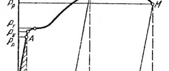
The graph of the relationship between stress τ and relative shift γ obtained during testing is called a shear diagram. In appearance, these diagrams differ from the tensile diagram only in that they do not have a section with a drop in stress (load). Here, as in the case of tensile materials, there is a point Рв, corresponding to the limit of proportionality under shear τпз. This tension is the limit of validity of Hooke's law. The slope of the straight line characterizes the shear rigidity of the material, and the tangent of the angle γ determines the shear modulus of elasticity G. Point Рт corresponds to the shear yield strength τТ. Further on the diagram there is a significant increase in stress with increasing shear strain. At point Pk, the sample is destroyed, and the corresponding stress is called the tensile strength τпч or temporary resistance τвр. This value is determined by dividing the load (shearing force F - in this case the maximum value) by the cross-sectional area of the sample A, taking into account the number of shear planes (in this case two planes):
The destruction of a beam during shear occurs in the form of a cut, which corresponds to the section PvRk in the diagram. Shearing is thus the final stage of shear failure. In this regard, the shear strength condition can be replaced by the shear strength condition: τav= Qy/S≤[τav].
There is a certain relationship between the shear strength τпч and the tensile strength: τпч = (0.6-0.8)σпч - for steel.
For testing, round steel samples with a diameter of 6-20 mm are used.
3. Work order
1. Before testing, familiarize yourself with the design of the testing machine and the cutting device.
2. Measure the diameter d0 of the sample with a caliper with an accuracy of 0.1 mm and sketch it.
3. Insert the sample into the hole in the cutting tool. Put the machine to work. During loading, the sample experiences a shear along two planes from a force directed perpendicular to the axis of the sample. Record on the scale of the force meter the magnitude of the load at which the sample will collapse. The maximum force value is considered the breaking load.
4. Set the “operation mode” knob on the control panel of the machine to the “reset” position and lower the moving parts of the machine. Turn off the pumping unit and disconnect the machine from the electrical network.
5. Remove the sample and examine the nature of its destruction.
6. Based on the recorded destructive load Fmax and shear area A0, determine the ultimate strength of the material during shearing using the formula:
.
7. Draw the appearance of the samples before and after the experiment. Note that shear is a complex deformation in which shear is accompanied by bending and crushing, indicate signs of the presence of bending and crushing.
8. Prepare a report on the work done in accordance with Appendix 1.
Control questions:
- What is pure shift?
- What stresses occur during pure shear?
- How is Hooke's law written for shear?
- Types of joints in which the material is sheared?
- What types of deformations additionally occur during shearing?
- What is the relationship between the tensile and shear strength of steel?
Annex 1.