The 1A62 screw-cutting lathe is one of the successors of the famous DIP-200 family, the first machines of which were manufactured in 1932 at the Moscow Machine Tool Manufacturing Plant. Its predecessor was 1D62, which changed the name DIP-200 to a new alphanumeric designation developed by ENIMS in 1937.
The 1D62 went into production in 1937 and was produced for eleven years. In 1948, it was replaced by the model 1A62 lathe, which had improved performance characteristics, as well as a modernized control system and improved ergonomics. It was produced for eight years - until 1956. It was replaced in the production line by the famous 1K62, which was produced for 18 years.
Purpose and scope
The technical characteristics of the 1A62 screw-cutting lathe will allow you to perform almost the entire traditional range of turning operations: turning and boring surfaces with different generatrices, thread cutting with cutters and threading tools, processing of end surfaces, as well as drilling, countersinking, and reaming.
1A62 is used for semi-finishing and finishing processing of various metals and alloys for single and small-scale production. The main consumers of this machine are tool production and repair departments of energy, metallurgy, automotive, mechanical engineering, mining and agricultural enterprises. In the fifties of the last century, this was one of the most popular lathes of this size, and it is still used in small industries and by individuals.
Purpose of the equipment
The purpose of the 1A62 corresponds to other universal screw-cutting lathes. It is used for turning, drilling, threading and other turning operations. The initial workpiece can be installed both in the chuck and in the centers. The quality of turning allows the machine to be used as part of finishing and semi-finishing equipment groups. The instruction manual recommends using this model for the manufacture of single or small-scale products.
Model specifics and technical characteristics
Compared to the previous model, which was produced without significant changes for more than ten years, the 1A62 screw-cutting lathe has had the following technical characteristics improved:
- the spindle speed increased by 300 rpm (up to 1200), and the number of steps increased to 21 for forward rotation and to 12 for reverse rotation;
- a 7 kilowatt electric motor is installed;
- instead of a flat main drive belt, a V-belt drive is used;
- a more powerful friction clutch is used;
- a reverse mechanism is installed to change the feed direction during thread cutting;
- the tailstock design has been strengthened;
- the quill diameter has been increased to 70 mm;
- an electric pump was added to supply coolant from a reservoir located in the rear leg;
- The irrigation lubrication system was replaced with a circulation one.
The controls also underwent significant changes, which significantly increased the convenience of the machine operator:
- To set the spindle speed, three handles are used: one circular (with a dial with divisions) and two positional;
- Below the caliper there is a longitudinal feed dial;
- New quick-acting rotary tool holder allows one-handed positioning to any angle;
- The gearbox has been modernized for ease of control (the number of handles has been reduced).
Options
The 1A62 machine inherited the main dimensional parameters from the previous model, including the maximum turning diameter above the support of 210 mm. The main technical characteristics of the machine are given below.
Processing dimensions (mm):
- maximum turning diameter above the bed - 400;
- the maximum length of the workpiece being processed is 1500;
- spindle bore diameter - 36.
Spindle (rpm):
- spindle speed range - 12÷1200;
- reverse spindle speed - 18÷1520;
- spindle cone - M5.
Caliper (mm):
- maximum longitudinal stroke - 1400;
- maximum transverse stroke - 280;
- The maximum stroke of the cutting slide is 110.
Tailstock quill (mm):
- diameter - 70;
- maximum stroke - 150;
- cone - M4.
The machine is equipped with two electric motors: the coolant system (0.125 kW) and the main drive (7 kW).
Design features of the machine
The tailstock of the 1K62 lathe, consisting of a plate, a body with a mounting hole and a retractable quill, can move along the bed guides. Adjustment of the reach, fixation of the quill and rear center, which are installed in the tailstock, are carried out using a special handle. The mounting hole in the quill has a conical shape, which allows you to fix various tools in it: drill, reamer, countersink, tap, etc.
Kinematic diagram 1K62 (click to enlarge)
The gearbox of the 1K62 machine and its tailstock are distinguished by the simplicity of their design, which is based on a number of shafts (one of them is frictional). A pulley is located on one of the gearbox shafts, to which torque is transmitted from the device’s electric motor. In addition, the box contains a friction clutch, various blocks (triple, intermediate, etc.), supports and rolling bearings. A special oil pump is responsible for lubricating all moving parts of the gearbox.
Gearbox mechanism
Tailstock 1K62
The longitudinal and transverse movement of the machine support occurs thanks to the lead shaft and lead screw, the rotation speed of which is regulated by the 1K62 feed box. In the design of this machine unit, which is responsible for the feed speed, the following elements can be distinguished: a three-stage Norton block, shafts, switchable couplings, interlocked gears, and bearings.
The feed box is located at the bottom of the equipment frame, which greatly facilitates its maintenance and repair. The shaft of this box is driven into rotation using replaceable guitar wheels, through which it is also connected to the spindle of the device, which ensures consistency between the rotation of the spindle and the feeds made by the support of the unit. A wheel moves along the feedbox shaft, at one end of which there is a gear, and at the second there is a handle that can be installed in one of ten positions.
Feed box device
The most important element of the lathe apron is the nut, which is in connection with the lead screw and ensures the longitudinal movement of the caliper. The nut, which often fails due to wear, has the ability to self-align relative to the lead screw, which ensures accurate movement of the caliper.
The machine apron, in which the rotation of the lead shaft and lead screw is converted into longitudinal movement of the carriage and transverse movement of the support, operates according to the following scheme.
- Rotation from the drive shaft is transmitted to the worm wheel through several successively arranged gears.
- The movement of the caliper, possible in four directions, is ensured by couplings with end teeth, which are engaged at the required moment.
To engage the queen nut and engage it with the lead screw, a handle located on the face of the machine apron is used. The simultaneous use of the drive shaft and lead screw to impart longitudinal movement to the caliper is eliminated, for which a special shaft with cams is responsible.
Apron of machine 1K62
The most important thing is that the support consists of such structural elements as:
- upper sled, which is also called incisor sled;
- cross carriage;
- bottom slide.
The movement of the carriage along the guides of the lower slide is ensured by a screw and a backlash-free nut. Rotation of the screw can be transmitted through a handle (manual control) or a gear wheel (automated control). On the upper surface of the carriage there are circular guides with a rotating plate. The design of this plate also provides guides on which a four-position tool holder is installed.
Machine support 1K62
The characteristics of such a unit and its design features make it possible to install a rotating plate and, accordingly, a tool holder with a tool at any angle to the longitudinal axis of the machine. To fix the rotary plate in the required position, special clamping bolts are provided in the carriage design. Even a novice turner can use such a device if he carefully studies the instructions for the equipment.
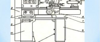
Organization of machine control
The control of the 1A62 machine is completely manual, so all processing controls are located directly on its main components and assemblies. On the front part of the headstock at the top there are handles for switching operating modes of the gearbox, and just below there are handles for the feed box. Under the gearbox there are three buttons for turning on and off the lighting of the working area, the general power supply of the machine and the electric pump of the coolant system. To the right of the feed box is a push-button block for turning the main engine on and off.
Below the caliper on the apron there are control handles and a handwheel for manual movement of the caliper. On the support itself there are handles for moving and fixing the tool holder. The tailstock is equipped with a handwheel for moving the quill and a handle for fixing it.
Caliper and cutting slide
The support serves for longitudinal and transverse feeding of the cutting tool; a turning tool is attached to its upper part. The main assembly units in its composition are:
- lower slide;
- Bottom part;
- turning part;
- cutter slide with tool holder.
The movement of the lower slide is carried out parallel to the axis of the machine and is done either manually or from the lead screw through the apron drive. The lower part is located on the upper guides of the lower slide. Its lateral movement is carried out either manually or from the apron drive. The rotating part of the caliper can rotate left and right at an angle of 45°. The cutting slide moves manually along the longitudinal guides of the middle part.
To control the mechanical movements of the caliper components, four rotary handles located on the apron are used. These controls enable and disable the following types of movements:
- caliper reverse;
- mechanical movement;
- longitudinal or transverse feed;
- lead screw nut.
For manual control of the support mechanisms, use the handwheel for manual movement of the carriage, located on the apron of the machine, as well as three handles on the support itself, which perform the following functions:
- transverse positioning of the caliper;
- fixing the tool holder;
- movement of the cutting slide.
The types of threads and feeds transmitted to the apron mechanism are adjusted by the controls located on the feed box.
Machine spindle assembly
The spindle assembly of the 1A62 machine is located in the headstock and includes, in addition to the spindle itself, a gearbox, which is used to change its speed and direction, as well as a gearbox that supplies the required type of feed and a given rotation speed to the machine support. The gearbox receives rotation from the main electric motor of the machine via a belt drive.
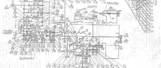
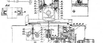
Machine diagram 1A62. Screw-cutting lathe. Kinematic
A kinematic diagram is a graphical diagram of the display of working units and blocks of a structure mechanism. The basic kinematic diagram shows the sequence of transmission of motion from the engine through the intermediate mechanism to the working parts of the product and their relationship. Kinematic diagrams specifically depict only those elements of the assembly structure that take part in the transmission of motion, these include intermediate gears, running rods and clamps, shafts, drive pulleys, couplings, etc. The design of any assembly mechanism that has moving parts is drawn in in the form of graphics on the diagram with solid lines alternating with dotted lines, respectively marking each element with numbers and subsequent decoding. There are spatial kinematic diagrams of mechanisms, which are usually depicted in the form of expanded diagrams. They are obtained by combining all axes in one plane and then projecting them onto the plane. Such diagrams make it possible to understand the sequence of motion transmission. On a kinematic diagram it is possible to display individual elements of other types of circuits that directly affect its operation, for example, electrical ones. The kinematic diagram begins to be read from the engine, which is the source of movement of all parts of the mechanism. By installing each element of the kinematic chain shown in the diagram sequentially according to the symbols, its purpose and the nature of the transmission of motion are revealed.
You can download the kinematic diagram of the 1A62 machine for free with high resolution using the link below:
Operating rules
Compliance with operating rules and routine maintenance guarantee the operability and stability of the performance characteristics of the 1A62 screw-cutting lathe during periods between scheduled repairs. Caring for equipment includes both maintaining cleanliness and order directly on the machine and in the working area of the machine operator, as well as monitoring the condition of its components and assemblies. In addition, it is necessary to carry out the regulated checks and activities provided for in the “Care and Maintenance Manual” of this machine.
After the end of the work shift, the machine operator must disconnect it from the power supply, remove tools, fixtures and equipment from the machine, clean its shavings and conduct an external visual inspection of the mechanisms to determine their serviceability. It is also necessary to check the condition of grounding and protective elements: fences, casings and screens.
Before starting a work shift, visual inspection is carried out in the same order. After which it is necessary to check the oil levels in all mechanisms of the machine and only then check the machine at idle speed.
The lubrication system of moving parts of the machine requires special control. The Manual lists control and technical measures that must be performed at the beginning of each shift to ensure that all moving mechanisms of the machine are lubricated. The lubrication system of the 1A62 screw-cutting lathe uses one type of industrial lubricant - machine oil “L” (according to modern classification - industrial oil I-30A).
Oil check
Checking and filling oil into the main components and units of the machine is carried out in the following order:
- Gearbox. The oil level is checked using the indicator on the neck (the norm is the upper level). Before starting work, it is necessary to clean the plate filter by turning the special handle located on the box body. The timing of oil changes is regulated. After starting the machine, it should be changed the first time after ten days, the second time after 20. Then the oil is changed every 35-40 days.
- Gearbox. Oil is poured to the upper level of the oil indicator. The frequency of oil changes is the same as for the gearbox.
- Apron. To lubricate the worm gear, oil must be poured through the hole in the flange to its bottom edge.
- Caliper. There are nine oil nipples on the bottom and top of the caliper that lubricate all moving parts of the caliper. Oil must be added to them every shift. In addition, each shift it is necessary to lubricate the guides of the upper part.
- Tailstock. Lubrication of the quill, screw and bearing is carried out by two oil nipples, which must be filled with oil every shift.
- Guitar. The body of the guitar has a reservoir for oil, which is poured into it up to the level of the oil indicator. The oil change intervals are the same as for the gearbox.
- Lead screw. Before starting a work shift, it must be lubricated with machine oil along its entire length. To lubricate the lead screw supports, as well as the roller supports, three oil nipples are provided, which must be filled with oil every shift. The vertical roller bearing receives lubrication through a separate oiler, to which oil is added once a week.
Machine lubrication and cooling of the processing area
The most important components of the machine, such as spindle supports, headstock elements, etc., are lubricated using a special system - in automatic mode. Lubrication of the remaining rubbing elements occurs at the moment when the elements of the gear joints begin to rotate, which simply spray the lubricant around themselves.
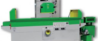
Lathe 1V62G in the production workshop
The design of the machine provides several points through which lubricant is supplied to its rubbing elements. There are such points at:
- equipment frame (lubricant is supplied here through rack and pinion gears);
- an apron (for this purpose, a special hole is provided in its design);
- carriage (separate spool).
In order to use the correct composition to lubricate the unit components, it is necessary to select it according to the table available in the user manual. The same table contains information about the norms for refilling such a composition and the frequency of its replacement.
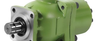
The coolant necessary to protect the processing zone from overheating is supplied to it through a special pump (X14-22M), which is mounted on one of the machine stands. This pump can pump up to 32 liters of coolant per minute. In addition, the unit’s cooling system has a container that can hold 25 liters of coolant.
Workspace dimensions
The processing space of metal-cutting equipment depends on the type, layout and geometric dimensions of the machine. Its dimensions limit the maximum dimensions of the workpiece that can be placed in the working area of the machine. In addition to the technical parameters of the equipment, these limitations also depend on the shape of the part and the location of the machined surfaces on it. For horizontal lathes, the workspace is usually divided into two types: for shaft-type parts and for disk-type parts.
The 1A62 lathe has a traditional layout and is classified as universal. For it, the maximum dimensions of a “shaft” type part are 220 mm in diameter and 1400 mm in length. A disc type part can have the following dimensions: 400 mm in diameter and 100 mm in height. Overall dimensions are not the only limitations when performing turning operations and are directly related to the weight of the workpiece. Thus, the maximum weight of the product when turning in the chuck of a lathe is 500 kg, and between centers - 1500 kg.
Characteristics of parts
Spindle
Necessary in order to fix the part being used. A moment passes through the built-in gearbox, which rotates from the power plant of the machine itself.
Spindle parameters:
Spindle of lathe 1A62
- The diameter and size of the through mold will be 36 mm.
- The permissible bar size is no higher than 38 mm, since it passes through this spindle.
- There are several stages of rotation (for direct transmission - 21, and for reverse rotation - about 12).
There is an indicator that determines how much the spindle head rotates. For a straight line, it varies from 11.5 to 1200 revolutions per minute. In case of reverse rotation, the value will be 18-1500 rpm.
Caliper
It is located so that the cutter moves under the workpiece. It is he who determines the operation of the machine, because the accuracy and quality of manufacturing parts depends on it.
The caliper parameters are:
Lathe support 1A62
- The longitudinal carriage is shifted somewhere by 65.9–140 centimeters.
- The underground carriage moves up to 28 centimeters as much as possible.
- It has several gear stages, transverse and longitudinal, the diameters of which will be 35 centimeters.
- There are several values for gears (longitudinal 0.08–1.59 revolutions per minute, transverse from 0.027 to 0.522 revolutions per minute).
- The set thread parameters are 19 for threaded threads and 20 for inch threads. Range and measurements of steps from 1–
Cutting slide
Cutting slide of lathe 1A62
They are necessary so that the cutting head moves evenly and enters the thread. They influence the quality of operations and the production of the parts themselves. In order for the cutting slide to move, it is enough to press the handwheels and levers, which are evenly located on the machine.
Cutting slide parameters:
- The greatest displacement will be approximately 113 millimeters.
- The division will be exactly 0.05 millimeters.
- Allowable rotation angle is up to 90 degrees.
- The cross-section of the cutter holder is allowed to be exactly 25*25.
Tailstock
This part is necessary to ensure that the workpiece is stably fixed. Special mechanisms have also been added that help fix the installed cone related to the center of the spindle head. The turning head moves only along the axis of the installed part.
Tailstock parameters:
- The diameter and size of the quill is approximately 70 millimeters.
- The holes are installed - Morse 4.
- The maximum allowed displacement of the quill is 150 millimeters.
- The division will be about 0.1.
Manufacturer information
The 1A62 screw-cutting lathe was produced from 1948 to 1956 at the Moscow Machine Tool Plant named after. A.I. Efremova. Before the revolution, this enterprise belonged to the Bromley brothers and was engaged in the production of various metal products. The plant was nationalized in 1918, and four years later, at the request of the labor collective, it was renamed “Red Proletarian”. Along with the new name, the company received a new specialization: the production of machines for metal and woodworking. The plant began reconstruction and construction of new production facilities. And in 1923, the first turning equipment was produced - machines of the TN series of three standard sizes.
The key year for the “Red Proletary” was 1930, when the design of a more powerful standardized machine called DIP (“Let's catch up and overtake”) began. Just two years later the first machine was manufactured and tested, and by the end of 1932 the company produced the first 25 DIP-200. The next year, the company was already producing 300 machines per month, and in 1934 it began producing larger-sized DIPs with indices 300, 400, 500. At the end of the thirties, DIP-200, in accordance with the newly adopted ENIMS classification, received a new designation - 1D62. During the war, “Red Proletary” produced machine tools (including those specialized for the needs of the defense industry) and produced artillery shells.
After the war, “Red Proletary” not only produced new types of lathes, but also designed them for other factories, thus becoming the leading enterprise in the industry for turning equipment. In 1948, the plant began production of the 1A62 machine, which replaced the legendary DIP-200, and the following year mastered their mass production. In 1951 the enterprise was named after A.I. Efremov - Minister of Machine Tool Industry of the USSR in 1941-1949. In 1951, a prototype of the now famous 1K62 was created. Two years later, this model went into production and was produced until 1971. In total, more than two hundred thousand of these machines were produced during this period. In the sixties, the company mastered the production of specialized machines and CNC turning equipment.
Since 1971, “Red Proletary” began producing 16K20 machines, and two years later began mass production of them, and in various configurations: with copiers, indication, CNC, etc. In the seventies, the plant had the largest production volumes in its entire history and supplied machine tools not only to the CMEA countries, but also to foreign countries. Since 1983, the company began mass production of CNC machines. At the same time, the plant stopped production of 16K20 machines and switched to production of the MK6056 screw-cutting lathe.
In the early 90s, the company faced difficult times. First, the demand for CNC machines fell almost to zero, then for universal machines, and by the mid-90s, “Red Proletary” produces only a few hundred machines a year. 1999 - the plant moved to a new production site, but with only part of the previous equipment.
Over the next ten years, the plant made an effort to regain at least part of the domestic market, which during this time was filled with foreign products, but in general its efforts were not crowned with success. In 2011, the company stopped producing machine tools, and its new owners announced the leasing of production and office space as its main activity. In 2016, it was announced that the production of turning equipment (including CNC ones) would be resumed, but the plant has not yet recorded any significant success in this matter.
Main engine and gearbox
One motor is used to drive the gearbox and feed shafts. It is mounted on a frame inside the front frame of the frame and develops up to 10 kW at a maximum shaft speed of 2000 rpm. High motor power provides high technical characteristics of the 1K62 metal lathe. Optionally, the machine could be equipped with a main drive with reduced power and rotation speed (7.5 kW and 1460 rpm, respectively).
Torque from the engine is transmitted to the input shaft of the gearbox using a belt drive. Since the engine power is high, the drive uses five (or four for a less powerful version) parallel belts. A friction clutch is installed on the input shaft of the box, allowing the spindle to rotate in both directions.
The direction of rotation is set by handles located at the level of the chip tray. By lifting the handle up, forward rotation is set, and by lowering it, reverse rotation is specified. In the middle position, the spindle band brake is activated. The gearbox has 23 gears with output shaft speeds in a wide speed range of 12.5...2000 (1460) rpm.
To lubricate the components, a separate oil pump is installed, supplying lubricant to highly loaded components. The plunger-type pump is driven by an eccentric on the input shaft of the box. The oil reserve is 3.7 liters and is located in the main tank at the bottom of the headstock housing. To monitor the serviceability of the lubrication system, there is an inspection eye in the top cover of the gearbox. When the system is working properly, a trickle of oil is visible through the peephole. To clean the oil, the machine has a plate filter.
Caliper and cutting slide 1A62
The 1A62 caliper, like similar units of lathes of other models, is responsible for the movement of the cutting tool relative to the workpiece. The characteristics of this element of the machine directly affect the accuracy of technological operations, as well as the functionality of the equipment.
The 1A62 lathe support has the following technical capabilities:
- the longitudinal carriage moves at 650, 900 and 1400 mm, the transverse carriage moves at a distance of up to 280 mm;
- number of stages of longitudinal and transverse feeds – 35;
- feeds can be made within the following limits: longitudinal – 0.082–1.59 mm/rev, transverse – 0.027–0.522 mm/rev;
- number of thread parameters to be cut: metric – 19 (pitch from 1 to 12 mm), inch – 20 (pitch – 2–24 threads/inch), modular – 10 (pitch – 0.5–3 modules), pitch – 24 (pitch – 7–95).
The cutting slide of the 1A62 lathe, which serves to more accurately move the cutting head, is controlled by several flywheels and control levers. This allows you to achieve the following operating characteristics of this unit:
- maximum movement value – 113 mm;
- in accordance with one division of the dial, the slide moves by 0.05 mm;
- the maximum angle through which this unit can be rotated is 900, while the rotation scale division value is 10;
- maximum cross-section of the cutting tool holder – 25x25 mm;
- the number of turning tools that can be simultaneously installed in the tool holder is 4.
It should be noted that the cutting slide of the 1A62 lathe is mechanically driven.
Subtleties of working with shaped blanks and conical parts
The technical characteristics of the 1K62D modification allow turning and cutting the required threads on conical-shaped parts, as well as shaped blanks. Processing of these blanks is carried out using two methods.
It is necessary to achieve displacement of the tailstock housing in the transverse plane. At a certain angle of location of the axis of the centers and the axis of the workpiece itself, the cutter is capable of turning conical parts. But due to the asymmetrical arrangement of the center holes relative to the installation centers, it is impossible to make a cone of an ideal shape.
Using a copying module for operation, which is fixed to the rear of the frame with brackets.
Bracket for fixing the copy module
By correctly selecting the fastening angle, it is easy to achieve the ideal cone-shaped part.
This processing method allows you to obtain a universal cone; the part will be of any acceptable length. This type of processing allows you to obtain a cone of the correct shape.
If you replace the copying cone ruler with a shaped one, the functionality of the machine expands even further. Specialists can process the shaped surfaces of step shaft blanks.
The 1K62D modification machine supports maximum load modes and impact processing of parts. A big advantage is the unpretentiousness of the choice of workpiece materials; it is easy to work even with steel, cast iron, durable parts.
Machine spindle assembly
The spindle assembly of the 1A62 lathe is responsible for fixing the workpiece during its processing, as well as for transmitting rotational motion to it from the main drive of the device.
We list the characteristics of this unit:
- through hole diameter – 38 mm;
- the maximum diameter of the rod inserted into the spindle assembly is 36 mm;
- rotation speed: forward – 11.5–1200 rpm, reverse – 18–1520 rpm;
- number of settable rotation speeds: forward – 21, reverse – 12.
The internal Morse seat cone in the spindle assembly of the 1A62 lathe has an M5 category.
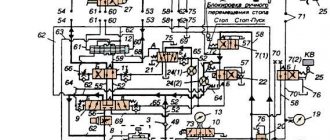
Schematic and wiring diagrams of the 1A62 machine (click to enlarge)