The profession of “turner” was popularized in the late 70s and until the 90s. And the TV-6 lathe and its predecessor TV-4 helped make it popular. Now the new generation unit has completely taken over the function of a training lathe. This device is used to train students who will subsequently become specialists in their field. This device has a rather modest limit of work performed, however, this is enough to perform simple tasks.
The 6 6 lathe can be considered one of the lightest, which allows it to be installed in large quantities in one room prepared for turning work (in educational institutions, workshops, etc.).
Dimensions of equipment and workspace
The TV-6 lathe is characterized by the following value:
- 5 m long;
- 5 m wide;
- 4 m high;
- its weight is up to 300 kg.
Such dimensions turn out to be extremely small for this kind of units, because in order for turning to be carried out, a set of mechanisms is required (including the engine), which take up a lot of space. The workspace is located in the center of the machine tabletop and has dimensions in mm:
- 1100 in length;
- 470 width;
- 110 height.
This is the space that is required to perform any operation on the equipment. Above this working area there is a transparent protective casing that prevents chips from accidentally getting into the eyes, as well as foreign objects from entering the working area, while you can observe the progress of the work process.
Features of operation
During operation, the guides of a metal-cutting lathe must be subject to regular inspection in order to eliminate malfunctions of its individual elements. Their wear will lead to the formation of backlash and a decrease in the processing accuracy of the part and workpiece.
They must be clean and lubricated with technical oil in a timely manner. If necessary, they should be replaced with new ones by following
Particular attention during operation of the TV-6 machine should be:
- Pay attention to the V-belt transmissions of the drive mechanism, in which the belts become loose. They must be periodically checked so that the tension on one branch of the belt corresponds to the required - 10 kg;
- eliminate spindle vibrations by tightening the spindle assembly with a nut. If the measure does not bring the desired results, then the bearings need to be replaced;
- by adjusting the nuts and grinding the ends of the rings, eliminate minor gaps that arise during the processing of parts.
What is possible for TV-6
This turning tool is capable of performing the following types of tasks:
- trimming blanks;
- drilling washers and rods;
- cutting parts;
- spline selection;
- thread cutting;
- chamfering.
All work is done with cylindrical and conical workpieces. In the Improved version, work can be carried out on milling parts.
Such operations are performed with limitations in the capabilities of the equipment. Here are the technical characteristics that make it possible to operate the TV-6 lathe:
- the longest workpiece length is 350 mm, while the processed part is 300 mm, and 50 are in fastening;
- diameter of the workpiece maximum 200 mm;
- The maximum turning speed is 170 rpm.
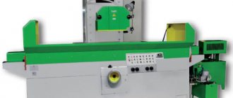
Metal lathe TV-6
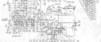
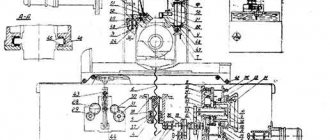
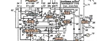
Location of the components of the TV6 screw-cutting lathe
Location of the components of the TV6 screw-cutting lathe
Specification of components of the TV6 screw-cutting lathe
- Handle for switching the speed of rotation of the drive shaft and lead screw
- Handle for switching the speed of rotation of the drive shaft and lead screw
- Guitar gear shift knob
- Spindle speed switch handles
- Spindle speed switch handles
- Caliper cross feed handle
- Tool holder fastening handle
- Upper slide handle
- Quill mounting handle
- Tailstock mounting handle
- Quill feed flywheel
- Mechanical feed control handles
- Mechanical feed control handles
- Button
- Caliper movement flywheel
- Buttons to turn the motor on and off
What does the unit consist of?
Turning a part or turning out a new one is a rather complex job that requires high precision. Therefore, to carry out this kind of function it is necessary to use complex mechanisms that are driven mechanically and electrically. The entire unit consists of several complex mechanical and electrical structures. Just like for the 4-TV unit, there is a set of elements for the TV-6 turning mechanism.
Here is a description of all the elements present in the TV-6 lathe:
- headstock;
- tailstock;
- bed;
- gearbox;
- caliper;
- bed guides;
- engine;
- caliper apron;
- pallet.
TS-TV6 details
Headstock functions
The headstock of the TV 6 screw-cutting lathe serves to hold the part, as well as to transmit rotational movements to the workpiece. The part is held by securing it in the headstock head. Also, the headstock, which is located on the left side of the frame, contains gears that transmit rotational movements. These gears are necessary for changing speed modes of rotation. Speed change is made by one of 3 switches located on the front of the headstock.
Purpose of the tailstock
It works in tandem with the front one, and it is located on the opposite side, that is, on the right side of the frame. The functional purpose of the tailstock is the same as the front one - holding and rotating the workpiece being processed. However, the tailstock tends to move on runners and does not contain a complex mechanism of gears.
The main task of the tailstock is to hold the part in the desired position, namely vertically. In the absence of this element, precession of the part during rotation is inevitable. But to perform work such as drilling holes, the tailstock is needed to feed the product onto the drill.
How the bed works
As with other units, the bed for the 6 6 lathe serves as a supporting structure. The necessary elements of the mechanism are concentrated on the frame. At the same time, the characteristics of this design must meet the necessary requirements. In this case, the frame has compact dimensions and can withstand up to 600 kg of weight, with the weight of the device itself being 300 kg.
Purpose of the feed box
The function of the feed box is to switch the speeds of the shaft and screw. To do this, there are two levers on the feed box panel that drive one of the elements - the shaft or the screw. Also, all gears are lubricated through the feed box.
Main design features
A universal screw-cutting lathe consists of main structural units, which are standard elements. These include:
- caliper;
- bed;
- thrust and spindle headstock;
- electrical equipment;
- drive shaft;
- guitar gears;
- a box that provides selection and change of feeds;
- lead screw - it is this detail that distinguishes a screw-cutting lathe from a standard lathe.
Depending on some features, the accuracy of the machine may vary. Therefore, universal equipment can be of both accuracy class N and increased – P.
Front and rear stock
The headstock or spindle has the main role of fixing the workpiece in processing and transmitting rotation to the workpiece from the electric motor.
The spindle is located inside the body of the headstock. A speed control handle is mounted on the outside of the machine body. The tailstock or thrust is necessary to fix the workpiece.
Caliper
The support is designed to move the tool holder with the cutter in the longitudinal, transverse direction relative to the axis of the machine. The lower part of the support is called the slide or carriage.
After a certain time of operation of the machine, the support will need to be adjusted, since otherwise the processing speed will decrease. Adjustment for gaps consists of tightening the wedge strip.
Compared to other parts, the caliper is large. The choice of tool holder is determined by the class of the machine. For large equipment, be sure to secure the cutters with an additional four screws.
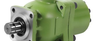
Gearbox
This is the main part of the spindle drive. It transmits engine energy to the rest of the machine. Another function is to change the spindle speed and the operating speed of the entire machine.
The box is built into the spindle head housing or in a separate housing block. The speed can be changed in a stepless or stepwise manner. The standard gearbox includes the following components:
- gear system;
- V-belt transmission;
- reversible electric motor;
- electromagnetic clutch with braking system;
- handle for changing gears.
The gearbox operates using gears.
Spindle
This is the main part of the machine, which is made in the form of a shaft with a conical hole for securing workpieces. To ensure that the part has high strength and durability, it is made of high-strength steel.
In the classic version, the spindle is made on high-precision rolling bearings. A special ring is installed on the support of the part, which ensures the accuracy of the machine.
There is a conical hole at the end of the structure. The spindle needs a cavity to install a rod that helps, if necessary, knock the center out of the seat.
The strength and durability of the spindle directly depends on the bearings available there.
bed
This is the main part of the machine, which is made using cast iron. All the most important parts and elements of this design are attached to it.
The frame itself consists of two steel beams. The beams, in turn, are connected to each other by stiffening ribs. Each beam has a connection to two guides.
The guides on both sides belong to the prismatic group. The flat-shaped guide is located inside on the left side.
Threading
There are several ways to cut threads using a screw-cutting lathe. For this, a die, tap, cutter and other types of tools are used.
With their help it is possible to cut internal and external threads
When using a cutter, it is important to fully comply with the technology. It includes:
- correct sharpening of the cutter;
- accurate adjustment of machine operating modes;
- using a template, correct installation of the cutter in the center of the part;
- measuring the resulting dimensions using gauges or templates.
In such work, defects in the form of sharp points, torn threads, scuffing and crushing are unacceptable.
Electrical control unit
The standard control unit for a screw-cutting lathe includes several handles and buttons:
- handle for setting the number of revolutions;
- control system for setting cutting surface parameters;
- handles for caliper control.
A CNC machine has a more complex structure, but can work without operator participation at intermediate stages.
Apron
In the apron of a screw-cutting lathe there are mechanisms that convert the rotational movement of the lead screw and the lead shaft into the translational movement of the caliper.
Why is a caliper apron needed?
One of the main elements of the machine is the support apron. Its task is to feed the cutter. The apron itself consists of an element lying on skids, the movement of which is carried out along a perpendicular line with the workpiece. Also, on the apron there is a caliper and control levers for the movement of the caliper and apron. In operation it looks like this:
- the cutter is fed onto the part by levers located on the apron;
- the caliper apron itself moves left or right, removing a layer of metal from the rotating part.
Caliper functions
For the TV 6 screw-cutting lathe, the support serves as a holder for cutters, as well as their feed towards the center of the diameter of the workpiece or part. The support located on the apron feeds the cutter throughout the entire working process.
It is worth noting that a malfunction of this element can lead to inaccurate turning, which is extremely undesirable in turning. In order for the caliper to serve for a long time, all the bolts on it must be tightened as much as possible, this reduces vibration and increases service life.
Information about the manufacturer of the educational screw-cutting lathe TV-9
The TV-9 table-top screw-cutting lathe is produced by the Rostov plant of small-sized machine tools MAGSO, KomTeh-Plus, founded in 1956.
The MAGSO plant is part of the ComTech financial and industrial group, which has existed in the machine tool equipment market for several years and has priority in the production of small-sized metal-cutting machines: lathes, milling, vibrating, sharpening, drilling, which equip schools, vocational schools, colleges, institutes, repair and installation organizations of all regions of Russia.
The machines produced by this company are well known on the Russian market and a number of CIS countries, thanks to the first models of screw-cutting lathes TV-4, TV-6. Model TV-9, deservedly enjoying the reputation of high-quality and reliable equipment. An important feature of the machine is its efficiency and low operating costs.
What are the bed guides, pallet and motor needed for?
The caliper apron and tailstock move along these guides or runners. The skids have the character of powerful and smooth rails, the evenness of which plays a role in the quality of the work performed. It is worth noting that on this version of the turning unit, the bed guides had no cases of malfunction. Their quality is designed to last for many years of service.
The pallet has the shape of a tabletop located on the bed, under all elements of the machine. It serves to collect lubricant (oil) flowing from lubricated mechanisms during operation.
The electric motor is located under the pallet, at the bottom of the frame. It drives the entire mechanism thanks to a belt drive.
For accurate operation of the machine, it is necessary to monitor the serviceability of each element, promptly lubricate the component parts with oil, and keep the unit clean. For safe operation, you must adhere to the rules for using electrical equipment.
Design
TV 6 lathe includes the following parts:
- mode control unit;
- cabinets located in front and behind;
- screen for protection;
- trough for the supply of lubricating fluid;
- front and rear stock;
- machine apron;
- supporting frame;
- electrical components;
- guitar;
- protective casing.
The mode control unit is driven by gears of the transmission unit and contains:
- 2 shafts;
- 5 gears with different characteristics;
- block gears;
- travel roller;
- couplings;
- a circle-shaped nut;
- switch handle;
- drain cover.
The handle on the front side of the adjustment unit makes it possible to set the indicators of the thread created on the part.
The handle, which is located on the feed unit panel, allows you to turn on the drive roller. It is not possible to turn on the screw and the drive shaft at the same time. A similar limitation is present in machines used in production. Lubrication of all parts of the feed box (gears, contacting parts) is carried out thanks to the oil fluid, which is supplied from the trough through special wicks.
The cabinet located at the front is shaped like the letter “P”. Its rigidity is enhanced by special ribs located at the top and bottom. The electric drive of the machine is mounted at the back, and at the front there is a button that controls the reverse activation. A similar device has a cabinet located at the back. A panel with electrical equipment is installed on it.
The tailstock, which has a Morse taper mounting hole, contains:
- main part;
- hub body;
- connecting screws;
- quill;
- key screw;
- a flywheel that controls the movement of the quill;
- handles for securing the quill and tailstock.
The tailstock makes it possible to move the quill by 6.5 cm.
The supporting frame of the machine, through which all parts of the structure are combined and maintain their original location, has a box-like appearance and has several windows. There are 2 guide prisms on it. The frame itself is supported by a pair of pedestals.
One of the most important parts of the TV 6 machine is the apron, consisting of:
- 4 gears (2 worm and rack each);
- control handles;
- flywheel controlling manual feed;
- uterine nut;
- a stroke roller designed for longitudinal feed of the support element;
- shaft
The support element of the TV 6M machine includes 4 carriages. This part of the device is intended to fix the cutter and move it when processing the part. The cutter holder in which the tool is secured is located on the fourth carriage. It can move longitudinally along the guides of the third carriage. The 3rd carriage, fixed to the second, is considered to be rotating, and the second is fixed to the first, moving transversely.
To transfer torque from the gearbox to the feed box, a special unit called a guitar is used. The main part of the guitar is the bracket with the gears installed. Gears cannot be changed; therefore, the gear index provided by the guitar is considered constant and equal to one fourth.
Features of use
Even though the TV-6 device is considered a training device, when working on it you can obtain high accuracy and work with complex turning operations. The drive mechanism of the unit uses a V-belt drive, so regular checking of the belt tension is required.
With such a simple preventive measure, maximum power of the electric motor is used and the service life of the work is extended. When the tension is loosened, it is easy to adjust the belts by loosening the nuts and setting the required tension level.
Another common malfunction of the device is vibration when the spindle assembly rotates, due to the loosening of the screw connection. In such a situation, more qualified repairs are required, in case of possible bearing failure.
If gaps are detected in the spindle, grinding of the ends is necessary. But only in the case of minor gaps of a radial and axial nature.
Important!
The machine is highly reliable; with proper care, the unit will last for many years, providing maximum accuracy.
How to buy a used machine
- Warning: when buying from an ad in another region, you may end up with unscrupulous sellers. Or the product may not meet the declared condition, or they will offer a higher price. As a result, money for the trip will be thrown away. So it's better to look for an offer closer.
What to pay attention to when purchasing:
- Availability of chuck, jaws, tailstock, electric motor. Moreover, if the electric motor can still be purchased, then the tailstock is quite difficult to get (they are often sold for scrap metal, since they can be removed from the machine quite easily).
- It is necessary to make sure that the machine spindle rotates and the slide movement is activated. If the electric motor does not work, you can rotate the spindle manually using the drive pulley. If something doesn't rotate or move, there is obviously something wrong.
- Check how worn the rubbing surfaces are, as well as the radial chatter of the spindle and tailstock quill. Any fault found is a reason to reduce the price. If there are many faults, it is better to refuse the purchase even for a small amount. Because repairs can cost a pretty penny.
That's all that can be said in one article. Additional information can be found on thematic forums. It turns out that there are many people who enjoy learning the craft of turning and share their practical experience. Unfortunately, statements are sometimes controversial. In doubtful cases, it is better to seek advice from an experienced professional turner.
Cabinet
The design of the lathe divides the cabinet into two parts: front and back. They have a similar, but different structure.
The front cabinet is assembled in the shape of the letter “P”. To make the structure more durable, stiffening ribs are mounted at the bottom and top. The engine is located at the back of the cabinet. It turns on (off) by pressing a button located on the front of the cabinet.
The difference between the rear cabinet is that its design includes an electrical panel instead of a motor.