A machine for grinding flat metal surfaces is being produced at the Lipetsk Machine Tool Plant. Equipped with 2 types of tables - rectangular, round. It is used in the manufacture of bearings and other parts for cars, machine tools, and tractor equipment. The peculiarity of the operation of a profiled grinding wheel intended for processing shaped parts lies in the method of processing the end and peripheral surfaces.
Surface grinding machine 3L722V
The 3L722V surface grinding machine belongs to accuracy class “A”. Maximum dimensions of processed materials when secured in headstocks:
- length – 1250 mm;
- width – 320 mm;
- height – 400 mm.
Technical characteristics of 3L722V
Considering the dimensions of the work table, 1 meter long and 32 cm wide, we have to admit that in a static position of the workpiece it is impossible to cover the entire surface with the 3L722V grinding wheel without moving it. The table has a longitudinal feed. The main moving tool, the rotating grinding wheel, receives the feed direction from the spindle headstock in which it is mounted.
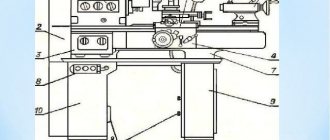
General view of the surface grinding machine 3L722V
In addition to the workbench on the 3L722V, fastening of workpieces weighing up to 400 kg is possible on a magnetic plate. Processing, with this arrangement, is carried out vertically. Only horizontal machining is possible for parts exceeding this value. Weight limit when placed on a table is 600 kg.
Download passport 3L722
Dimensions of parts processed with fixation on an electromagnetic plate in mm
| Dimensions | Maximum | Minimum |
| Length | 1250 | 50 |
| Width | 320 | 40 |
| Height | 280 | 3 |
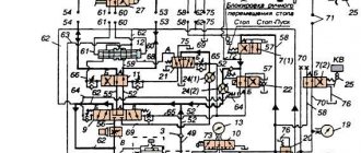
When operating 3L722V surface grinding equipment in the mode of processing parts on a table, a hydraulic system is used, which imparts a reciprocating speed to the working surface. There is only one direction.
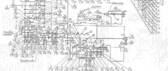
Kinematic diagram 3L722V
The rotation of the grinding wheel on the base model 3l722V is 1460 rpm. The machine operating manual consists of several sections:
- characteristics of electrical equipment;
- features of the first launch;
- description of operating modes;
- control circuit;
- debugging and maintenance;
- protection, sound signals;
- locking devices;
- stages of maintenance and debugging of mechanisms;
- list of electrical elements of a surface grinding machine and parts made of precious metals.
Surface grinding machine 3L722V
A machine for grinding flat metal surfaces is being produced at the Lipetsk Machine Tool Plant. Equipped with 2 types of tables - rectangular, round. It is used in the manufacture of bearings and other parts for cars, machine tools, and tractor equipment. The peculiarity of the operation of a profiled grinding wheel intended for processing shaped parts lies in the method of processing the end and peripheral surfaces.
The 3L722V surface grinding machine belongs to accuracy class “A”. Maximum dimensions of processed materials when secured in headstocks:
- length – 1250 mm;
- width – 320 mm;
- height – 400 mm.
Technical characteristics of 3L722V
Considering the dimensions of the work table, 1 meter long and 32 cm wide, we have to admit that in a static position of the workpiece it is impossible to cover the entire surface with the 3L722V grinding wheel without moving it. The table has a longitudinal feed. The main moving tool, the rotating grinding wheel, receives the feed direction from the spindle headstock in which it is mounted.
General view of the surface grinding machine 3L722V
In addition to the workbench on the 3L722V, fastening of workpieces weighing up to 400 kg is possible on a magnetic plate. Processing, with this arrangement, is carried out vertically. Only horizontal machining is possible for parts exceeding this value. Weight limit when placed on a table is 600 kg.
Download passport 3L722
When operating 3L722V surface grinding equipment in the mode of processing parts on a table, a hydraulic system is used, which imparts a reciprocating speed to the working surface. There is only one direction.
Kinematic diagram 3L722V
The rotation of the grinding wheel on the base model 3l722V is 1460 rpm. The machine operating manual consists of several sections:
- characteristics of electrical equipment;
- features of the first launch;
- description of operating modes;
- control circuit;
- debugging and maintenance;
- protection, sound signals;
- locking devices;
- stages of maintenance and debugging of mechanisms;
- list of electrical elements of a surface grinding machine and parts made of precious metals.
3L722V machine characteristics
Buy this machine without intermediaries:
Specifications:
Machines model 3l722v are designed for precision processing of flat and shaped surfaces. The machine can be equipped with sine plates, allowing processing of parts at different angles.
Accuracy class B Largest dimensions of workpieces with nominal wheel diameter, mm: without electromagnetic plate: length ……………………………. 1250 width…………………………. 320 height …………………………… 400 on the electromagnetic plate: length ……………………………. 1250 width……………………………. 320 height …………………………… 280 Smallest dimensions of workpieces fixed on an electromagnetic plate, mm: length …………………………… 50 width ………………… …………. 40 height ……………………………… 3 Maximum mass of processed products, kg: on an electromagnetic plate ………………. 400 without electromagnetic plate……………… 600 Distance from the spindle axis to the working surface of the table, mm: minimum……………………………. 210 maximum …………………………… 625 Limits of table movement speeds (stepless regulation), m/min ……….. 2 …35 Grinding wheel according to GOST 2424-75 ……….. PP450x80x203 Grinding wheel rotation speed spindle, min -1 .. 1460 Grinding speed at the largest diameter of the grinding wheel, m/s …………………… 34.4 Transverse movement of the stand, mm …………… 430 Transverse movement speed of the stand, m/min: during accelerated movement, not less than …….. 1.2 in editing mode ……………………….. 0.150 Limit of intermittent transverse feed of the rack per table stroke (stepless regulation), mm/stroke ….. 1.. 60 Vertical movement of the grinding head, mm: maximum ……………………………. 415 per one division of the dial ………………….. 0.002 per one revolution of the dial …………………… 0.2 with jog feed …………………… 0.002…0.120 micrometric manual ………… ……… yes Accelerated vertical movement of the grinding headstock, mm/min ……………………… 200 Amount of emergency rebound of the grinding headstock, mm, not less ……………………….. 1.0 Overall dimensions of the machine , mm: length…………………………………… 4810 width……………………………….. 2660 height…………………………………….. 2660 Weight of the machine (without hydraulic unit, cooling unit, electrical cabinet), kg………………. 6100 Machine weight, kg ………………………….. 7150 Relative indicator of material use, kg/kW ... 554 Relative indicator of electricity use, kW/ohm ... 1.4 Corrected sound power level, dBl ... 99
Buy this machine without intermediaries:
mashinform.ru
Overhaul of a surface grinding machine
When operating the machine, not only the working tools wear out, but also the internal rotating components. This leads to a decrease in the quality of metalworking. Modernization and repair of 3L722V surface grinding machines is carried out in Lipetsk and the Moscow region.
When using a machine for up to 20 years, failure of its main components is unlikely. But every year the possibilities of new technologies of 3L722V equipment increase. In order for the machine to meet the latest requirements, it needs modernization and modification. Based on the fact that the basic scheme does not fundamentally change, and the basic parameters of the working surfaces are maintained, the modernization of the machine will not affect the appearance and dimensions of the equipment. For the master servicing the machine, the manufacturer’s manual for operation and maintenance of the 3L722V will remain relevant. Only some power characteristics of electrical equipment will change. What needs to be taken into account when replacing the characteristics of improved units in the instructions. A major overhaul of equipment manufactured half a century ago involves a complete update of the electrical systems. The general circuit will remain the same, but in operation the machine will become quieter and more powerful, which is justified by replacing the DC electric motor with a similar one operating on AC.
During the modernization process, when replacing the engine of a surface grinding machine, the gearbox and control system are changed. Manual settings are being replaced by CNC. Installing software control only makes sense on equipment that meets certain accuracy requirements. This quality is achieved by serviceable lead screws, bearings, gear reducers, smooth guides, and a well-functioning lubrication system.
What to expect from modernization
Modernization with the replacement of outdated electrical components is carried out with units of domestic and foreign production. For the machines of the Lipetsk plant, units manufactured by Siemens and Omron are suitable, thanks to which the relay-controlled circuit becomes modern - digital. The operating instructions for equipment updated in this way will change dramatically.
During a major overhaul, the mechanical components of surface grinding equipment are replaced by a third. Modernization concerns mainly electric drives. Most often, the electrical filling is replaced completely.
After a major overhaul with the installation of a CNC, the manufacturer’s operating manual can be considered outdated; it does not correspond to the updated systems. Management becomes easier.
File Description
Data sheet for a surface grinding machine with a rectangular table and a horizontal spindle
Mod. 3L722A, 3L722V, 3L722V-70, 3L722V-80, 3L722V-001, 3L722V-002
Lipetsk Machine Tool Plant (LSPO)
1990 – 3L722V_3L722A_3L722V-70.djvu (13.57 MB)
1991 – 3L722A_3L722V.djvu (8.96 MB)
Manual. Electrical equipment. Electrical circuit diagrams – 3L722A_3L722V_Elektrooborudovanie.djvu (6.61 MB)
Drawings and diagrams – 3L722V_big.djvu (2.02 MB)
Download the passport and electrical diagrams of this machine from another plant (Leningrad):
Passport 3L722A Surface grinding machine with a rectangular table and a horizontal spindle
Name of publication: Part 1: Operating manual (3Л722А.000.000 РЭ) – 41 pages Part 2: Machine electrical equipment – 21 pages Part 3: Electrical diagrams – 47 pages Part 4: RG48-3D722-02 Complete hydraulic drive (RG48-3D722-02.00 .000 RE) – 46 pages Publication issue: — Year of publication: 1990 Number of books (folders): 4 Number of pages: 155 Cost: Negotiable Description: Complete set of documentation
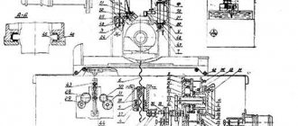
Contents: Part 1: Operating manual (3Л722А.000.000 РЭ) 1. General information - General view of the machine 2. Basic technical data and characteristics - Sketch of the spindle end - Sketch of the table grooves 3. Delivery set 4. Instructions for safety measures 5. Composition of the machine — Location of the machine components — Location of the machine controls 6. Design and operation of the machine and its components — Kinematic diagram — Vertical feed mechanism — Cross feed reducer — Installation of the table synchronizer sensor 7. Hydraulic and lubrication systems of the machine — Hydraulic schematic diagram — Diagram lubrication principle - Location of lubrication points - Installation of lubrication 8. Installation procedure - Scheme for transporting the machine - Installation drawing - Scheme for installing the protective tape 9. Possible malfunctions and methods for eliminating them 10. Instructions for operation, maintenance and repair 11. Materials for wearing parts - Worm wheel (3L722A.166.201) - Worm (3L722A.166.401) - Gear wheel (3L722A.322.401) - Block gear (3L722A.322.402) - Gear wheel (3L722A.322.403) - Rolling bearings arrangement diagram 12. Acceptance test report 13 Certificate of conservation 14. Certificate of packaging Appendix 1: Testing the machine for compliance with standards of accuracy and rigidity Appendix 2: Certificate of final control of electrical equipment Appendix 3: Information on the content of precious metals Appendix 4: List of metrological equipment used when testing the machine for compliance with standards accuracy
Description of the operation of the centralized lubrication system of the 3L722V machine
In order to improve the thermal operating conditions of the hydraulic drive station, the front doors, rear and top panels may not be installed.
Figure 14 shows the location of the lubrication points. The guides are lubricated from an individual lubrication station (Fig. 15), into tank 4 of which filtered oil T22 GOST 32-74 or VNLI NP-403 GOST 16728-78 is poured in the amount indicated on the plate on the lubrication unit.
Pressure setting value 0.5. 0.8 kgf/cm² is controlled by pressure gauge 2. To prevent movement of the stand and table in the absence of lubrication, a type I pressure switch RD8/10-000-03 is installed on the guides in the lubrication system. Adjustment and visual control of the lubrication on the guides is carried out by the lubrication throttle block 8 (see Fig. 13). When tightening the block adjusting screws, the gap changes, and hence the amount of oil consumption. The required amount of lubricant supplied to the guides is ensured when the floats of the throttle lubrication block 8 are located between the two red lines.
Oil flows to the guides through fine filter 3 through pipelines 13. 14.15. 16, 17 (see Fig. 13). Oil is drained from the guides by gravity through pipelines 9, 10, II, 12 into the cavity of the guide part of the rack frame, and from there through pipeline 18 into the lubrication station reservoir.
Filter 7 serves to clean the oil when pouring it through the filler neck. The lubrication unit includes a pump 6 with an electric motor.
Grinding machine 3L722 scheme
A universal surface grinding machine with a rectangular table and a horizontal spindle, model ZB722 (Fig. 1), is designed for grinding the planes of parts using the periphery of a wheel. Depending on the material, shape and size, the parts to be sanded can be fixed either on an electromagnetic plate or directly on the working surface of the table.
Kinematic diagram
The movement from flywheel A (Fig. 6) is transmitted through gears 1.2, cam clutch B, conical pair 3.4 to nut 5 connected to lead screw 6. Since the nut is fixed against vertical movement, when it rotates, screw 6 will move in the axial direction, feeding the carriage with the grinding headstock.
Bed and table
A table 2 carrying a cylinder 3 moves along the guides of the frame 1 (Fig. 7). The frame guides, which open when the table moves, are closed by two flexible tapes 4. The tapes pass into the table windows formed by the table body and the screwed guides 5. The ends of the tapes are stretched and fixedly fixed to the ends of the bed. When the tape is tensioned, the nuts 6 are released and by rotating the screw 7, the block 8 with the tape attached to it is moved down, after which the nuts 6 are tightened again. In order for the tapes to adhere to the frame guides when the table moves, there are rollers 9 rotating on axes 10, secured in screwed strips 11.
Column
Column 1 (Fig. 8), screwed to the bed frame 2, is a rigid cast frame with guides along which, using a system of rollers 3 located in the separator 4, the carriage 5 moves. Backlash in the guides is eliminated by adjusting the strips 6 and the wedge of the carriage 7 For visual control of the size of the sanded product, an indicator 8 and a bracket 9 with an adjustable stop are provided.
Vertical feed mechanism
The vertical feed mechanism (Fig. 9a, 96) is mounted on the front panel of the frame 1 and closed with covers 2 and 3. The cylinder of the feed mechanism 4 is attached to the body 5. To increase the durability of the ratchet mechanism, the pawl 6 is made in the form of an asterisk with six teeth. Replacing a worn tooth with a new one is done by turning the pawl. To enable accelerated movement, half-coupling 7 is moved by lever 8 to the extreme right position, at which flywheel 9 is disconnected from the mechanism. The cam 10 turns on the limit switch 11, preparing the accelerated movement from the electric motor. Accelerated movement is only possible as long as the button is pressed. To eliminate the gap in the gearing of the drive, the movements of the overlap 12, gears 13 and 14 are made double. A pin 16 is fixed in the sleeve of the folding rigid stop 15, which rests against a fixed block 17, which determines the constant position of the folding stop. The gears are lubricated by oil flowing from the frame guides through tube 18 and collecting at the bottom of the housing. Sector 19 is used to automatically stop feeding after removing the established processing allowance. Rotating together with dial 20, sector 19 covers the swing zone of pawl 6, gradually reducing the feed to zero.
Propeller drive support
The screw drive support (Fig. 9 a) serves to transmit movement from the vertical feed mechanism to the column gearbox. The support body 21 is mounted on the mating plane of the pedestal 22. The pinion shaft 23 rotates on two tapered roller bearings. Bevel gears 23 and 24 are lubricated by gravity through tube 25.
Column reducer
The column gearbox (Fig. 9 a) serves to transmit movement from the vertical feed mechanism through the screw drive support to the carriage. The gear shaft 23 of the screw drive support rotates the bevel gear 24, which sits on a key on the bimetallic nut 26. When the nut 26, fixed in the axial direction with the help of two angular contact and thrust bearings, rotates, the screw 27 receives vertical movement. The carriage 28 moves along with the screw. The nut-lead screw pair is lubricated through a tube 29 from the lubricator mounted on the carriage.
INTRODUCTION
Grinding machines are equipment that uses an abrasive or diamond wheel as a cutting tool. The use of these machines is determined by high requirements for surface quality, dimensional accuracy, shape and position of the processed surfaces and the ability to process difficult-to-cut materials. Grinding machines, as a rule, receive workpieces that have been pre-processed on other machines, leaving a small allowance for grinding, the amount of which depends on the requirements for roughness and processing accuracy.
The type and design of the grinding machine is determined by the grinding scheme, which takes into account the shape of the surface being processed and its location relative to the working surface of the grinding wheel (machines for grinding the periphery or the end of the wheel) during processing. Also taken into account is the direction of feed movement (longitudinal and plunge grinding machines), the position of the main spindle (machines with horizontal or vertical spindles) and the method of installing the workpiece (center, chuck and centerless machines).
All grinding machines are characterized by high productivity, which is determined by the high-speed grinding mode, which allows removing a large volume of material per unit time (up to 500 mm 3 /min per 1 mm of wheel width) and extensive automation of the processing cycle.
Surface grinding machines are designed for finishing of flat and shaped surfaces on parts of different sizes.