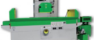
Surface grinding machine 3D711VF11
The 3D711VF11 surface grinding machine with a cross table and a horizontal spindle is designed for processing, in a cycle or outside the cycle, with the periphery of an abrasive or diamond wheel, flat surfaces made of steel, cast iron and other materials, mounted on a table mirror or in auxiliary devices. Within the limits allowed by the dimensions of the grinding wheel casing, the machine can turn the end of the wheel, and with the use of devices for shaped dressing of abrasive wheels, mechanisms for dividing and fastening parts, which are equipped with the machine at the request of the customer, it is possible to process grooves and shaped profiles using the method of multi-pass plunge-cut grinding.
The machine is used in single, small-scale and mass production.
Manufacturer information
The 3E711B surface grinding machine is manufactured in Orshansk at the Krasny Borets machine-tool plant.
The plant was founded more than a hundred years ago. And the surface grinding machine began to be produced only 60 years after its discovery. The first metal cutting machine, 3711, whose characteristics were distinguished by high-precision indicators, was released in 1967. And the universal surface grinder GS 3E711V has become a successful replacement for the old version 3G71.
Technical characteristics of the 3D711VF11 machine
The technical characteristics of the 3D711VF11 machine are the main indicator of the suitability of the machine for performing certain work on machines. For surface grinding machines, the main characteristics are:
- Table work surface size
- The largest dimensions of the sanded product
- Circle speed
- Table longitudinal movement speed
Below is a table with the technical characteristics of the 3D711VF11 surface grinding machine. More detailed technical characteristics of the machine can be found in the passport of the 3D711VF11 machine located below.
| Quantities | ||
| Machine accuracy class according to GOST 8-82 | IN | |
| Largest dimensions of the workpiece (LxWxH) | mm | 990x280x375 |
| Weight of the installed workpiece, no more | kg | 220 |
| Outer diameter of grinding wheel | mm | 300 |
| Internal diameter of grinding wheel | mm | 76 |
| Maximum height of grinding wheel | mm | 63 |
| Minimum height of grinding wheel | mm | 40 |
| Working surface of the table (LxW) | mm | 630x200 |
| Number of T-slots | 3 | |
| Groove width | mm | 14 |
| Distance between grooves | mm | 50 |
| Table mounting surface (LxW) | mm | 990x200 |
| Distance from the spindle axis to the table mirror | mm | 550 |
| Maximum manual table movement | mm | 700 |
| Maximum manual movement of the caliper | mm | 250 |
| Spindle speed | rpm | 2230 |
| Working table feed | m/min | 2…35 |
| Caliper working feed | m/min | 0,3…40 |
| Automatic vertical roughing feed (stepped) | mm | 0,01…0,09 |
| Automatic vertical finishing feed (stepped) | mm | 0,001…0,009 |
| Speed of rapid movements of the caliper | m/min | 2,14 |
| Speed of rapid movements of the grinding head | m/min | 0,3 |
| Main drive power | kW | 4 |
| Dimensions of the machine without separately located units (LxWxH) | mm | 2595x1775x2035 |
| Weight of the machine without separately located units | kg | 2300 |
| Weight of separately located units and electrical equipment | kg | 650 |
Attention! The technical specifications given in the above table are for reference only. Machines produced by different manufacturers and in different years may have characteristics that differ from those given in the table.
Features of flat grinding
The surface of the finishing disc determines the type of grinding: end or periphery. The main characteristics of peripheral grinding methods:
- mortise grinding. it is used when working with parts where the width is not greater than the height. also in cases where the plane is limited by tubercles. During this work, the disc wears out quickly, and this requires frequent adjustments. great accuracy is not achieved during this work;
- deep type of grinding. when carrying out such an action during the period of one table stroke at a low feed speed of the longitudinal type, full allowances are removed.
- grinding using variable cross feed. it allows you to finish any volumetric areas with high quality. If the transverse feed is inconsistent during the last movements, you need to set a small feed depth. this is required to reduce the inaccuracy that the disk creates as a result of wear;
- grinding using constant cross feed. it is carried out constantly, and its value for each movement should not be higher than half the circular height. If you compare this method with the previous one, it creates a more precise finish.
Machine passport 3D711VF11
This instruction manual ( Machine passport 3D711VF11 ) “Surface grinding machine 3D711VF11” contains information necessary for both the operating personnel of this machine and the employee directly involved in working on this machine. This manual is an electronic version in PDF format of the original paper version. This documentation contains the Operating Manual (instructions) for the 3D711VF11 grinding machine.
CONTENT
- General information
- Basic technical data and characteristics
- Contents of delivery
- Safety instructions
- Machine composition
- Design, operation of the machine and its components
- Machine lubrication
- Installation procedure
- Operating procedure
- Possible malfunctions and methods for eliminating them
- Features of disassembly and assembly during repairs
- Certificate of acceptance
- Preservation and packaging information
- Instructions for maintenance, operation and repair
download the passport of the 3D711VF11 surface grinding machine in good quality from the link below.
Colored electrical diagram of the surface grinding machine 3E711B1
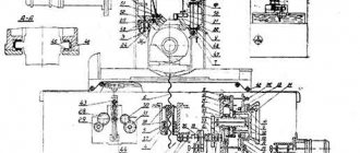
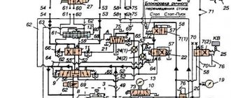
In Fig. Figure 4 shows a functional diagram of a contactless asynchronous thyristor electric drive for transverse feed. It contains the following functional elements: Tp3 - three-phase supply transformer; VBZ - contactless limit switch; PTK – starting thyristor switch; TTK - braking thyristor switch; FI1 - pulse shaper for controlling the PTK thyristor; FI2 - pulse shaper for controlling the TTK thyristor; EVD - element of temporary dosing of the transverse feed value; KG - PTK thyristor damping circuit; KB - blocking circuit; МІІ — executive electric motor. The given functional diagram gives a clear idea of the relationship and interaction of the functional elements of the drive. During operation of the machine, each time its table is reversed to work out the next transverse feed, the signal from the VBZ through FII is sent to the PTC, which simultaneously supplies the supply voltage from the transformer Tr3 to the electric motor M11 and turns on the electric drive. In this case, the electric motor M11 begins to work out the given feed, and the electric drive begins counting the time of dosing the displacement amount. At the moment of expiration of the set dosing time for the displacement value, the signal from the electric motor is sent to the control unit, which turns off the PTC, thereby removing the supply voltage from the M11 electric motor. Immediately after the PTC is turned off, the signal from it through FI2 is accessed by the TTK, which, when turned on, slows down the MII electric motor. To prevent the failure of the feed during transient processes associated with turning off the PTC and braking the M11 electric motor, signals from the CG and TTK are sent to the KB, which issues a prohibition signal to FI1, preventing the passage of the command to start the next serve until it is completely completed processing the previous one.
We will consider in detail the features, construction and operation of the functional elements of the drive, their connection and interaction with each other using the example of electrical circuit diagrams (Fig. 3, 4).
Tp3 - three-phase supply transformer
TP3 performs a number of functions in the drive circuit. It is the power source for all functional elements of the drive circuit, with the exception of VBZ and FI1. Transformer Tr3 ensures minimal differences in the drive circuit when installing it on machines supplied for export; in this case, all changes in the drive circuit are reduced only to the use of a supply transformer with a voltage of the primary windings corresponding to the voltage of the supply network.
Tp3 partially performs the functions of pre-connected active-inductive resistances that improve transient processes and drive energy. The secondary windings of the TrZ transformer are connected at one end to the PTK, and at the other to the executive motor M11 and TTK.
PTK - starting thyristor switch
The PTC consists of a three-phase input rectifier bridge D1, in the DC circuit of which fuse Pr1, low-resistance resistor R1 and starting thyristor DU1 are connected in series. A circuit consisting of capacitor C1 and resistors R2 and RЗ connected in series is connected in parallel with the thyristor DU1. This purpose protects the thyristor DU1 from an excessive rate of increase in the forward voltage on it (dU/dt), etc., which must satisfy the condition (dU/dt), etc.
The secondary windings of transformer Tr3 are connected at one end to the variable inputs of rectifier D1. In the initial state of the drive (pause), the thyristor DU1 is closed: the entire voltage of the secondary windings of the transformer Tr3 is applied to it through the rectifier D1, and the electric motor M11 is de-energized. When a feed command is given, the thyristor DU1 opens under the influence of a control pulse supplied to it from FI1, the secondary windings of the transformer Tp3 are, as it were, connected by a star and voltage is applied to the electric motor M11 - the feed begins.
Resistors R1 and RЗ perform dual functions. At resistor R1, at the moment the supply starts, when thyristor DU1 opens, a voltage drop occurs, which is supplied to the electric drive as a supply. As a result, the start of the feed is synchronized with the start of the timing of its dosing, which is important for ensuring the accuracy of the drive and eliminating the need to use a separate power source for the electric drive. Resistor R1 also plays the role of an additional active pre-connected resistance, which, along with transformer Tr3, has a positive effect on improving transient processes and drive energy. Resistor RЗ is part of the RC circuit that protects the thyristor DU1 from the excessive rate of increase in forward voltage, and, in addition, acts as a connecting element between the PTC and FI2, since after the dosing time of the supply value has expired, when the thyristor DU1 is closed, the voltage drop that occurs across the resistor R3, supplied to FI2 as a feeder.
EVD - element of temporary dosing of the transverse feed amount
The electric drive is built on the principle of an adjustable RC circuit with a threshold trigger. It consists of elements for stabilizing the supplied voltage - resistor R6 and zener diode D4; timing elements - electrolytic capacitor C3; variable resistors R4 - cross-feed regulator, R6 - tuning regulator, R5 - maximum cross-feed limiter (see these resistances in the main diagram at the output of the cross-feed block); elements of the threshold trigger device - forward conduction transistors T2 and reverse conduction T1, zener diode D6, which performs the function of a threshold element, resistors R7, R8, R9, R1O. Resistor R1O acts as a matching element between the EVD and the CG. The EVD works as follows. At the moment the supply begins, the voltage drop that occurs in the PTC across resistor R1 is supplied to the input of the electric drive, and then stabilized by the zener diode D4 and supplied to the timing elements. Capacitor C3 begins to charge through the cross-feed regulators, the setting of which determines the time constant of its charge. As soon as capacitor C3 is charged to a voltage equal to the breakdown voltage of zener diode D6, transistor T2 will begin to open slightly. As a result of the action of positive feedback through the circuits created in the threshold trigger device by transistor T1, an avalanche of opening of transistor T2 is ensured. Transistor T2, having opened, supplies a voltage pulse to the CG, which is a command to close the thyristor DU1 PTK and end the supply. Thus, the dosing time for the supply value is the time required to charge the capacitor C3 from zero to a voltage equal to the reference voltage of the zener diode D6. Due to its smallness, we neglect the voltage drop across the emitter-base junction of transistor T2. In order to speed up the return of the electric motor to its original state after the thyristor DU1 PTK closes and the electric motor M11 is de-energized, a diode D5 is connected in parallel with the supply regulators, creating a low-resistance discharge circuit of the capacitor C3: C3-R4-R6-D5– SZ.
KG - thyristor quenching circuit PTK
The KG consists of a series circuit, which includes a diode D7 and a quenching thyristor DUZ, a capacitor C4 and an inductor L. The KG is connected in parallel with the thyristor DU1 PTK. In the initial state of the circuit, when the PTC is closed and the electric motor M11 is de-energized, capacitor C4 is charged through diode D7 to a voltage equal to the voltage applied to the thyristor DU1 of the PTC.
After the start of feed processing, this voltage on capacitor C4 continues to be maintained, since the diode D7 is connected in relation to it in a non-conducting direction, and the thyristor RES is closed (the discharge of capacitor C4 along the leakage circuits during feed processing is insignificant and can be neglected). After the time for dosing the supply value has expired, the thyristor of the DUS opens and activates the KG damping circuit, which is an oscillatory LC circuit. During the first half-cycle of current oscillations in the circuit, capacitor C4 is recharged along the circuit C4-DUZ-DU1-L-C4, and during the second half-cycle, through the circuit C4-L-DUI-D4-D7 – C4, the thyristor DU1 PTK is extinguished. After the thyristor DU1 closes, capacitor C4 will charge again and the CG will return to its original state.
FI2 - pulse shaper for controlling the TTK thyristor
FI2 consists of a pulse transformer ITr1 and diodes D1O - in the primary winding circuit and D11 - in the secondary winding circuit, preventing the appearance of false pulses at the control transition of the thyristor TTK. The primary winding FI2 of diode D10 is connected to resistor R3 PTK, and the secondary winding is connected through diode D11 to the control junction of thyristor DU2 TTK. FI2 works as follows. After the dosing time of the supply value has expired, as soon as the thyristor DU1 PTC closes and the electric motor M11 is de-energized, a voltage pulse taken from the resistor R3 PTC is applied to the primary winding ITR1 FI2 at the moment the protective RC target of the thyristor DU1 PTC is triggered through diode D10. The transformed voltage pulse that appeared after this on the secondary winding of the pulse transformer Itr1 is applied through diode D11 to the control transition of the thyristor DU2 TTK, thus turning on the brake system of the drive.
TTK - braking thyristor switch
The TTK contains a three-phase rectifier D2, connected by variable inputs to the electric motor M11. A brake thyristor DU2 and a cut-off diode DZ are connected in series to the DC circuit of this bridge. A C-circuit is connected in parallel to these elements, consisting of a resistor R4 and a capacitor C2 and serving to protect the thyristor DU2 from an excessive rate of increase in the forward voltage on it (dU/dt), etc. A matching resistor R5 is connected in parallel to the control transition of the thyristor DU2. TTC works as follows. While the feed drive is working, as soon as the dosing time for the feed amount has expired, the PTC will close and a control pulse will be sent from FI2 to the TTK, and the brake thyristor DU2 will open. In this case, the windings of the electric motor M11 through the bridge D2, the thyristor DU2 and the diode DZ appear to be short-circuited, as a result of which the electric motor M11 is braked. To close the braking thyristor DU2, a special quenching device is not required, since the braking process is self-extinguishing and, therefore, the thyristor DU2 will close as soon as the current flowing to it during braking of the electric motor becomes less than its holding current. After the braking thyristor DU2 closes, the TTK will return to its original state.
FI1 – pulse shaper for controlling the PTK thyristor
To start the next feed, the command from FI1 must be sent to the thyristor DU1 PTK. FI1 consists of rectification elements and supply voltage filters for the contactless limit switch VBZ: diode D15, resistor R17, electrolytic capacitor C7, resistor R16, matching FI1 with VBZ; noise suppression elements: capacitor C6, resistor R15, cut-off zener diode D14; elements of amplification and formation of the control pulse: reverse conduction transistors T3 and forward conduction T4, resistors R13 and R14, decoupling diodes D12 and D1Z and differentiating capacitor C5. FI1 works as follows. In the initial state FI1, when there is no signal to start feeding, the voltage at the output of the VBZ is less than the reference voltage of the zener diode D14. All this voltage therefore turns out to be applied to the zener diode D14, and transistors T3 and T4 are closed, and the control pulse does not arrive at the PTC. During the command to start feeding, a voltage pulse appears at the output of the VBZ, significantly exceeding the reference voltage of the zener diode D14, as a result of which the zener diode DІ4 opens and passes a current pulse through the target VBZ-DI4-base-emitter junction of the transistor T3-D13-C5-VBZ. In this case, transistor T3 opens and passes through its collector-emitter circuit a pulse of the emitter-base current of transistor T4. Transistor T4, controlled by this current, opens and passes a current pulse through its emitter-collector target through diode D12 to control the starting thyristor DU1 PTK. The duration of this pulse is determined by the charging time of the differentiating capacitor C5.
VBZ - contactless limit switch
As a VBZ, the drive uses a commercially available commercially produced non-contact limit switch BBK2O1-24, operating on the principle of a relaxation generator. The signal at its output appears every time the table is reversed, at the moment the diamagnetic plate crosses the target.
KB - blocking circuit
The blocking circuit is necessary to create blocking circuits that prevent the control pulse from FI1 from passing to the PTC to the beginning of the next feed when the starting thyristor DU1 of the PTC is extinguished or during braking of the electric motor M11, when the braking thyristor DU2 of the TTK is open. In the first case, this will lead to a failure of the suppression of the thyristor DU1 PTK (supply failure), and in the second - to a short circuit in the drive power circuit and the burning of the fuse link PrI. The KB consists of two diodes: D8 and D9, connected by cathodes to resistor R11. The action of the blocking circuit is as follows. When the starting thyristor DU1 PTK is extinguished at the beginning of the second half-cycle of the current oscillation in the CG, the differentiating capacitor C5 FI1 to the circuit C4-D8-R11-C5-DU1-D4-D7 – C4 is charged to a voltage several times greater than the voltage at the output of the VBZ at this triggered. This voltage reliably closes the diode D1Z, thereby preventing the formation of a control signal at the PTC. After the thyristor DU2 TTK opens and the braking of the electric motor M11 begins, the charge on the capacitor C5 continues to be maintained by the voltage of the secondary windings of the transformer Tr3 along the circuit TrZ-D2-DU2-D9-R11-C5-D1-Tr3. Transformer Tr3 in Fig. 3 and 4 are not shown. As soon as the forced braking of the electric motor M11 ends and the thyristor DU2 closes, the recharging of the capacitor C5 through the blocking circuits will stop and it will begin to discharge through the circuit C5-R15-R16-C5. The circuit will become ready to receive the command to process the next feed as soon as the voltage on capacitor C5 during its discharge becomes less than the voltage at the output of VB3.
Voltage oscillograms in critical sections of the cross feed drive are shown in Fig. eleven.
Operating manual for machine 3D711VF11. Electrical equipment.
This operating manual for the electrical equipment of the 3D711VF11 machine contains information necessary both for the maintenance personnel of this machine and for the employee directly involved in working on this machine. This manual is an electronic version in PDF format of the original paper version.
CONTENT
- Characteristics of electrical equipment
- Supply system
- Initial launch
- Operating mode
- Locks
- Alarm system
- Protection
- Safety instructions
- Installation and operating instructions
- Possible malfunctions and methods for eliminating them
download the operating manual for the electrical equipment of the 3D711VF11 surface grinding machine in good quality from the link below.
Surface GRINDING MACHINE WITH RECTANGULAR TABLE AND HORIZONTAL SPINDLE 3D711AF10-1
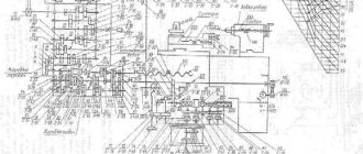
Surface grinding machines are designed for high-precision processing of flat surfaces of various products made of ferrous and non-ferrous metals, as well as grinding with the end of a wheel with a vertical feed of the wheel within the limits allowed by the grinding wheel housing, in conditions of mass, serial and single production. The kinematic diagram of the machine provides the following movements: - longitudinal automatic movement of the table from the hydraulic cylinder and manual movement from the flywheel; — transverse automatic movement of the cross support, accelerated movement and manual fine and coarse movement using flywheels; — vertical automatic movement of the grinding head, accelerated movement, manual fine and coarse movement using flywheels; - rotation of the grinding wheel.
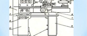
The base of the machine is a frame on which a cross support, a column, a control panel, and a transverse and vertical feed mechanism are installed. The machine support provides longitudinal and transverse movement of the table. The column ensures vertical movement of the grinding head. All working movements on the machine are automated. The longitudinal movement of the table is carried out by means of a hydraulic cylinder. Automatic and accelerated movement of the caliper is carried out through a belt drive from an asynchronous electric motor. Automatic vertical feed is carried out from a hydraulic motor through a gearbox, and accelerated movement from an asynchronous electric motor through a belt drive and gearbox. Manual movement of the cross support, grinding head and table is carried out using handwheels. The spindle rotates by an asynchronous electric motor. The hydraulic station of the machine is made as a separate unit and is installed to the right of the machine. The machine control panel is located on a bracket that is attached to the bed. A cooling system unit is installed on the left side of the machine.
COLUMN
The column is mounted on the rear wall of the frame and serves to carry out vertical movements of the grinding head, which is installed and rigidly fixed on its upper plane. The guide surfaces are formed by the column itself and strips screwed to the frame. Preload in the system of vertical guides is achieved: - in a plane parallel to the axis of the grinding spindle - using fitted rigid bushings and the force of disc springs; - in a plane perpendicular to the axis of the grinding spindle - due to the use of V-shaped guides. A worm gearbox for vertical movements is attached to the bottom plane of the column.
LEFT TRANSVERSE GUIDE
The left roller transverse rolling guide is U-shaped in cross-section and absorbs vertical and lateral loads. To ensure high rigidity and accuracy of the transverse movement of the caliper, the U-shaped guide is assembled with a preload, which is created by a wedge using a screw, then the wedge is fixed with screws.
CROSS CALIPER
The cross support provides transverse and longitudinal movement of the table. On the upper plane of the support there are longitudinal rolling guides (V-shaped and flat), along which the table moves. The table drive hydraulic cylinder is rigidly fixed between the longitudinal guides. A bracket is attached to the lower surface of the caliper, which is connected to the ball screw nut of the cross-feed mechanism. On the front wall of the caliper, under the protective shield, there is a guide bar along which the table reverse cams move. The cams have petals that interact with contactless switches located on the table. The position of the cams is adjusted depending on the length of the workpiece. At the front, on the left side of the support, there is a mechanism for manually moving the table.
TABLE
The table has a work surface with three T-shaped slots for installation and fastening of workpieces, an electromagnetic plate or an installation device. On the lower plane of the table there are longitudinal rolling guides, V-shaped and flat, as well as a gear rack, which ensures manual movement of the table from the gear of the manual movement mechanism. At the edges of the lower surface of the table there are brackets, to which the hydraulic cylinder rods are attached. A fencing of the working area is installed on the upper surface of the table. The coolant is collected in the table bath, and drained through an opening in the back wall of the table into a collection tank and then into the cooling tank.
CROSS FEED MECHANISM
The cross feed mechanism provides: - manual movement of the cross support; — automatic feeding; — accelerated movements; — disconnection of the flywheel by means of an electromagnetic clutch during automatic movements of the caliper.
GRINDING HEAD
The grinding head consists of a housing and a spindle. The spindle is mounted on high-precision angular contact rolling bearings, assembled with preload. The support end of the screw of the rolling ball screw for vertical movements is rigidly attached to the lower surface of the grinding head housing. In order to ensure protection of the front support bearings, special channels and labyrinths are made in the flange.
VERTICAL FEED MECHANISM
The vertical feed mechanism provides: - automatic vertical feed; — manual coarse or fine movement of the grinding head; — disabling the flywheel by means of an electromagnetic clutch during accelerated movements of the grinding head.
COOLING
The cooling consists of a welded tank on which an electric pump is installed to supply coolant and a magnetic separator to clean the coolant from metal slurry. The sludge is collected in a separate tank. The emulsion is drained from the table through a collector mounted on a support into a tray installed in a magnetic separator.
HYDRAULIC CYLINDER
The hydraulic cylinder is installed on the upper surface of the support and carries out the reciprocating movement of the table. The hydraulic cylinder rods are secured with nuts to the table brackets. The rods are sealed with rubber cuffs. In the extreme positions of the piston stroke, the table is braked using special cones.
HYDRAULIC DRIVE STATION
The hydraulic drive station is designed to ensure reciprocating movement of the table at an adjustable speed, bringing the table to the loading zone, driving the vertical feed mechanism and performing centralized automatic lubrication of the guides. The station operates on pure mineral oils with a kinematic viscosity of 30 to 35 mm2/s (r/St), at a temperature of 40°C, intended for hydraulic systems with antioxidant and anti-wear additives. Recommended oil brands: IGL-18 TU 38.101413-78, IGP-30 TU 38.10141Z-78.
LUBRICATION SYSTEM
The lubrication system is designed for centralized lubrication of all guides from the hydraulic system. It automatically starts working when the hydraulic drive of the machine is turned on. Oil enters the lubrication system from the hydraulic drive station through a filter with a filtration accuracy of 25 microns. The lubricant drainage is drained into a sump designed to clean the oil before draining it into the hydraulic station. The settling tank is equipped with a magnetic separator.