File Description
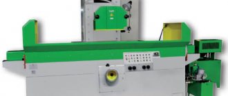
Data sheet for a surface grinding machine with a rectangular table and a horizontal spindle
Mod. 3L722A, 3L722V, 3L722V-70, 3L722V-80, 3L722V-001, 3L722V-002
Lipetsk Machine Tool Plant (LSPO)
1990 – 3L722V_3L722A_3L722V-70.djvu (13.57 MB)
1991 – 3L722A_3L722V.djvu (8.96 MB)
Manual. Electrical equipment. Electrical circuit diagrams – 3L722A_3L722V_Elektrooborudovanie.djvu (6.61 MB)
Drawings and diagrams – 3L722V_big.djvu (2.02 MB)
Download the passport and electrical diagrams of this machine from another plant (Leningrad):
Machine 3L722A. Surface grinding. Specifications
Technical characteristics of machines are the main indicator of the suitability of the machine for performing certain jobs on the machine. For surface grinding machines, the main characteristics are:
- Dimensions of the working surface of the machine
- The largest dimensions of the sanded product
- Table longitudinal movement speed
- Circle speed
Below is a table with the technical characteristics of the 3L722A surface grinding machine. More detailed technical characteristics of the machine can be found in the passport of the 3L722A machine, which can be downloaded below.
| Quantities | ||
| The largest dimensions of the workpiece with the nominal diameter of the circle without an electromagnetic plate (LxWxH) | mm | 1250x320x400 |
| The largest dimensions of the workpiece with the nominal diameter of the circle on the electromagnetic plate (LxWxH) | mm | 1250x320x280 |
| The smallest dimensions of the workpiece mounted on an electromagnetic plate (LxWxH) | mm | 50x40x3 |
| The largest mass of the workpiece on the electromagnetic plate | kg | 400 |
| The largest mass of the workpiece without an electromagnetic plate | kg | 600 |
| The shortest distance from the spindle axis to the working surface of the table | mm | 210 |
| The greatest distance from the spindle axis to the working surface of the table | mm | 625 |
| Table speed limits | m/min | 2…35 |
| Spindle speed | rpm | 1460 |
| Grinding speed at largest grinding wheel diameter | m/sec | 34,4 |
| Overall dimensions of the machine (LxWxH) | mm | 4810x2660x2660 |
| Machine weight | kg | 7000 |
Attention! The technical specifications given in the above table are for reference only. Machines produced by different manufacturers and in different years may have characteristics that differ from those given in the table.
Information about the manufacturer of the surface grinding machine 3L722V
Manufacturer of surface grinding machines 3L722, 3L722V, 3L722A – Lipetsk Machine Tool Plant, LSZ , founded in 1929.
In 1956, the tractor repair plant was reoriented to produce machine tools and renamed the Lipetsk Machine Tool Plant.
Model 3L722V machines are typical representatives of the range of surface grinding machines with a rectangular table of medium size and allow processing flat surfaces of a wide variety of parts with micron precision. When using additional devices, these machines can also process shaped surfaces.
Machine tools produced by the Lipetsk Machine Tool Plant, LSZ
INTRODUCTION
Grinding machines are equipment that uses an abrasive or diamond wheel as a cutting tool. The use of these machines is determined by high requirements for surface quality, dimensional accuracy, shape and position of the processed surfaces and the ability to process difficult-to-cut materials. Grinding machines, as a rule, receive workpieces that have been pre-processed on other machines, leaving a small allowance for grinding, the amount of which depends on the requirements for roughness and processing accuracy.
The type and design of the grinding machine is determined by the grinding scheme, which takes into account the shape of the surface being processed and its location relative to the working surface of the grinding wheel (machines for grinding the periphery or the end of the wheel) during processing. Also taken into account is the direction of feed movement (longitudinal and plunge grinding machines), the position of the main spindle (machines with horizontal or vertical spindles) and the method of installing the workpiece (center, chuck and centerless machines).
All grinding machines are characterized by high productivity, which is determined by the high-speed grinding mode, which allows removing a large volume of material per unit time (up to 500 mm 3 /min per 1 mm of wheel width) and extensive automation of the processing cycle.
Surface grinding machines are designed for finishing of flat and shaped surfaces on parts of different sizes.
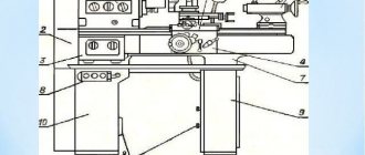
Location of components of the grinding machine 3L722V
Location of components of the grinding machine 3L722V
List of components of the grinding machine 3L722V
- bed
- Table
- Rack
- Grinding head
- Electrical cabinet
- Hydraulic unit
- Rack bed
- Remote Control
- Cross feed reducer
- Cooling unit
The table 2 moves back and forth along the guides of the frame 1 .
On the front part of the frame there is a control panel 8 and a cross-feed gearbox 9 .
A rack frame 7 is attached to the rear wall of the table frame, in the center, in which the transverse feed drive .
A slide moves along the guides of the stand frame, on which the stand 3 .
Grinding machine 3L722 scheme
A universal surface grinding machine with a rectangular table and a horizontal spindle, model ZB722 (Fig. 1), is designed for grinding the planes of parts using the periphery of a wheel. Depending on the material, shape and size, the parts to be sanded can be fixed either on an electromagnetic plate or directly on the working surface of the table.
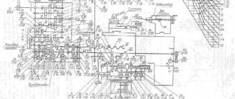
Kinematic diagram
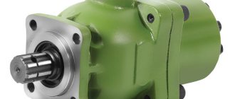
The movement from flywheel A (Fig. 6) is transmitted through gears 1.2, cam clutch B, conical pair 3.4 to nut 5 connected to lead screw 6. Since the nut is fixed against vertical movement, when it rotates, screw 6 will move in the axial direction, feeding the carriage with the grinding headstock.
Bed and table
A table 2 carrying a cylinder 3 moves along the guides of the frame 1 (Fig. 7). The frame guides, which open when the table moves, are closed by two flexible tapes 4. The tapes pass into the table windows formed by the table body and the screwed guides 5. The ends of the tapes are stretched and fixedly fixed to the ends of the bed. When the tape is tensioned, the nuts 6 are released and by rotating the screw 7, the block 8 with the tape attached to it is moved down, after which the nuts 6 are tightened again. In order for the tapes to adhere to the frame guides when the table moves, there are rollers 9 rotating on axes 10, secured in screwed strips 11.
Column
Column 1 (Fig. 8), screwed to the bed frame 2, is a rigid cast frame with guides along which, using a system of rollers 3 located in the separator 4, the carriage 5 moves. Backlash in the guides is eliminated by adjusting the strips 6 and the wedge of the carriage 7 For visual control of the size of the sanded product, an indicator 8 and a bracket 9 with an adjustable stop are provided.
Vertical feed mechanism
The vertical feed mechanism (Fig. 9a, 96) is mounted on the front panel of the frame 1 and closed with covers 2 and 3. The cylinder of the feed mechanism 4 is attached to the body 5. To increase the durability of the ratchet mechanism, the pawl 6 is made in the form of an asterisk with six teeth. Replacing a worn tooth with a new one is done by turning the pawl. To enable accelerated movement, half-coupling 7 is moved by lever 8 to the extreme right position, at which flywheel 9 is disconnected from the mechanism. The cam 10 turns on the limit switch 11, preparing the accelerated movement from the electric motor. Accelerated movement is only possible as long as the button is pressed. To eliminate the gap in the gearing of the drive, the movements of the overlap 12, gears 13 and 14 are made double. A pin 16 is fixed in the sleeve of the folding rigid stop 15, which rests against a fixed block 17, which determines the constant position of the folding stop. The gears are lubricated by oil flowing from the frame guides through tube 18 and collecting at the bottom of the housing. Sector 19 is used to automatically stop feeding after removing the established processing allowance. Rotating together with dial 20, sector 19 covers the swing zone of pawl 6, gradually reducing the feed to zero.
Propeller drive support
The screw drive support (Fig. 9 a) serves to transmit movement from the vertical feed mechanism to the column gearbox. The support body 21 is mounted on the mating plane of the pedestal 22. The pinion shaft 23 rotates on two tapered roller bearings. Bevel gears 23 and 24 are lubricated by gravity through tube 25.
Column reducer
The column gearbox (Fig. 9 a) serves to transmit movement from the vertical feed mechanism through the screw drive support to the carriage. The gear shaft 23 of the screw drive support rotates the bevel gear 24, which sits on a key on the bimetallic nut 26. When the nut 26, fixed in the axial direction with the help of two angular contact and thrust bearings, rotates, the screw 27 receives vertical movement. The carriage 28 moves along with the screw. The nut-lead screw pair is lubricated through a tube 29 from the lubricator mounted on the carriage.
Location of controls for the grinding machine 3L722V
Location of controls for the grinding machine 3L722V
List of controls for the grinding machine 3L722V
- Button "Hydraulic drive, start"
- "General stop" button
- Button “Demagnetization of electromagnetic plate”
- Button for turning on the reciprocating movement of the table
- Plate magnetization switch button
- Table motion stop button
- Button for turning on the reciprocating movement of the table
- Handle for changing the amount of coolant supplied to the cutting zone
- Stand movement stop button
- Button for turning on the push-pull movement of the stand
- Manual vertical microfeed handle
- Signal lamp
- Signal lamp
- Signal lamp
- Signal lamps
- Grinding wheel motor load indicator
- Signal lamp
- Signal lamps
- Table speed indicator
- Signal lamp
- Signal lamp
- Signal lamp
- Rack mode switch
- Grinding wheel rotation button
- Switch for vertical feed mode of the grinding head
- Buttons for accelerated vertical movement of the grinding head
- Button for inching vertical movement of the grinding headstock downwards
- Button for slow continuous vertical movement of the grinding headstock downwards
- Circuit breaker handle
- Buttons for accelerated vertical movement of the grinding head
- Switch for the nature of vertical feeds of the grinding head in automatic mode
- Switch for selecting the vertical automatic feed amount
- Knobs for adjusting the amount of strut travel
- Grinding wheel rotation stop button
- Coolant supply and cleaning system switch
- Knobs for adjusting the amount of strut travel
- Local lamp switch
- Automatic cross feed amount adjustment knob
- Handles for adjusting the size and location of the table stroke
- Pull-up movement button
- Handles for adjusting the size and location of the table stroke
- Toggle switch for setting table speed
- Handwheel for manual movement of the stand
- Traction operating mode of lateral movement of the rack
- Rack Micrometer Feed Handle
- Handle for turning on the manual micrometric feed of the stand
- Reset button DCI.F5290
Hydraulic and lubrication system of the grinding machine 3L722V
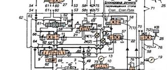
The hydraulic system of the machine carries out reciprocating movement of the table with stepless control of the speed of movement.
For a description of the operation of the hydraulic system, see the instruction manual for the complete hydraulic drive RG48.3D722.02 supplied with the machine.
To connect the complete hydraulic drive to the machine, use pipelines 5, 6 and 20 for drainage from under the cylinder covers according to the hydraulic circuit diagram (Fig. 12).
Proper and regular lubrication of the machine is of great importance for its normal operation and durability.
Lubrication must be done with lubricants specified in the lubrication chart (see table 1) or their substitutes given in the list of recommended lubricants (see table 2).
The machine uses a centralized lubrication system for the horizontal guides of the machine and table from a lubrication station.
ATTENTION! The first change of the filter element should be made as it becomes clogged, but no later than one month from the date of putting the machine into operation, the second - after three months, and then - guided by the instructions in the lubrication card.
Every day you need to monitor the filter clogging indicator located on its cover.
Passport 3L722A Surface grinding machine with a rectangular table and a horizontal spindle
Name of publication: Part 1: Operating manual (3Л722А.000.000 РЭ) – 41 pages Part 2: Machine electrical equipment – 21 pages Part 3: Electrical diagrams – 47 pages Part 4: RG48-3D722-02 Complete hydraulic drive (RG48-3D722-02.00 .000 RE) – 46 pages Publication issue: — Year of publication: 1990 Number of books (folders): 4 Number of pages: 155 Cost: Negotiable Description: Complete set of documentation
Contents: Part 1: Operating manual (3Л722А.000.000 РЭ) 1. General information - General view of the machine 2. Basic technical data and characteristics - Sketch of the spindle end - Sketch of the table grooves 3. Delivery set 4. Instructions for safety measures 5. Composition of the machine — Location of the machine components — Location of the machine controls 6. Design and operation of the machine and its components — Kinematic diagram — Vertical feed mechanism — Cross feed reducer — Installation of the table synchronizer sensor 7. Hydraulic and lubrication systems of the machine — Hydraulic schematic diagram — Diagram lubrication principle - Location of lubrication points - Installation of lubrication 8. Installation procedure - Scheme for transporting the machine - Installation drawing - Scheme for installing the protective tape 9. Possible malfunctions and methods for eliminating them 10. Instructions for operation, maintenance and repair 11. Materials for wearing parts - Worm wheel (3L722A.166.201) - Worm (3L722A.166.401) - Gear wheel (3L722A.322.401) - Block gear (3L722A.322.402) - Gear wheel (3L722A.322.403) - Rolling bearings arrangement diagram 12. Acceptance test report 13 Certificate of conservation 14. Certificate of packaging Appendix 1: Testing the machine for compliance with standards of accuracy and rigidity Appendix 2: Certificate of final control of electrical equipment Appendix 3: Information on the content of precious metals Appendix 4: List of metrological equipment used when testing the machine for compliance with standards accuracy
Part 2: Electrical equipment of the machine 1. Brief characteristics of the electrical equipment 2. Information about the power supply system of the electrical equipment 3. Initial start-up of the machine 4. Operating modes of the machine 5. Machine control circuit 6. Protection, alarm, interlocks 7. Maintenance, adjustment List of elements of the electrical equipment of the machine 8. List of elements of the electrical equipment of the machine 9. Information on the content of precious metals in the machine 10. Illustrations - Electrical circuit diagram of the cross feed control of the rack - Electrical circuit diagram of the thyristor starter (3L722A.859.000) - Voltage oscillogram - Functional diagram of the vertical feed - Functional diagram of the cross feed unit - Electrical circuit diagram of element T-101 - Electrical circuit diagram of element T-102 - Electrical circuit diagram of element T-103 - Electrical circuit diagram of element T-402 - Electrical circuit diagram of element T-403 - Connection diagram of wires of machine plug connectors - Layout of elements power switch (3L722A.854.040) - Layout of elements of the thyristor starter (3L722A.859.000) - Components of the machine and their connections
Part 3: Electrical diagrams - Electrical connection diagram of the complete hydraulic drive (RG48-3D722-02) - Electrical connection diagram (3L722A, V.850.000E4) - Electrical circuit diagram of the power part - Electrical circuit diagram - Electrical circuit diagram of the power switch for controlling the stepper motor - Electrical circuit diagram for controlling the transverse feed of the rack - Electrical circuit diagram for the table and rack reverse unit (3L722A.858.000) - Thyristor starter Electrical circuit diagram (3L722A.859.000) - Connection diagram for the machine plug connectors
Description of the operation of the centralized lubrication system of the 3L722V machine
In order to improve the thermal operating conditions of the hydraulic drive station, the front doors, rear and top panels may not be installed.
Figure 14 shows the location of the lubrication points. The guides are lubricated from an individual lubrication station (Fig. 15), into tank 4 of which filtered oil T22 GOST 32-74 or VNLI NP-403 GOST 16728-78 is poured in the amount indicated on the plate on the lubrication unit.
Pressure setting value 0.5. 0.8 kgf/cm² is controlled by pressure gauge 2. To prevent movement of the stand and table in the absence of lubrication, a type I pressure switch RD8/10-000-03 is installed on the guides in the lubrication system. Adjustment and visual control of the lubrication on the guides is carried out by the lubrication throttle block 8 (see Fig. 13). When tightening the block adjusting screws, the gap changes, and hence the amount of oil consumption. The required amount of lubricant supplied to the guides is ensured when the floats of the throttle lubrication block 8 are located between the two red lines.
Oil flows to the guides through fine filter 3 through pipelines 13. 14.15. 16, 17 (see Fig. 13). Oil is drained from the guides by gravity through pipelines 9, 10, II, 12 into the cavity of the guide part of the rack frame, and from there through pipeline 18 into the lubrication station reservoir.
Filter 7 serves to clean the oil when pouring it through the filler neck. The lubrication unit includes a pump 6 with an electric motor.