GRINDING MACHINE 3D711VF11
Surface grinding machines with a cross table and a horizontal spindle are designed for grinding flat surfaces with the periphery of an abrasive or diamond wheel of various parts mounted on a table mirror, a magnetic, electromagnetic plate and in a device made of steel, cast iron and other materials.
Within the limits permitted by the grinding wheel guard, it is possible to machine the wheel end outside the cycle. Using devices for dressing abrasive wheels (additional grinding heads, devices for dividing), installing and fastening parts, it is possible to grind inclined and shaped surfaces, grooves and ledges. The machines have automatic programmed stock removal, which provides roughing automatic vertical feed with a transition to finishing feed in the cycle, turning off the finishing feed when the specified size is reached, nursing and rebound of the grinding wheel. The machines are equipped with automatic transverse feed, automatic slide reverse, and table output to the loading area.
| Price including VAT for 1 piece | On request |
| Delivery time | 60 work/days |
| Guarantee period | 12 months |
| Delivery | By agreement |
| Start-up and commissioning works |
Technical data and characteristics of the 3E711B machine
| Parameter name | 3G71 | 3E711V |
| Main settings | ||
| Accuracy class according to GOST 8-82 | IN | IN |
| The largest dimensions of processed products (length x width x height), mm | 630 x 200 x 320 | 630 x 200 x 375 |
| The greatest height of the processed products with the largest diameter of the grinding wheel, mm | 325 | |
| Maximum height of workpieces with smallest grinding wheel diameter, mm | 375 | |
| Distance from the spindle axis to the table mirror, mm | 80…445 | 500 |
| Maximum mass of processed products, kg | 220 | |
| Accuracy parameters maximally achieved on the sample product | ||
| Product sample size, mm | 380 x 120 x 80 | |
| flatness, µm | 4 | |
| parallelism, µm | 5 | |
| roughness of the surface processed by the periphery of the grinding wheel, Ra | 0,16 | |
| Perpendicularity of the trajectory of the transverse movement of the table to the direction of its longitudinal movement, µm | 25 | |
| Machine work table | ||
| Dimensions of the working surface of the table (length x width), mm | 630 x 200 | 630 x 200 |
| Maximum manual longitudinal movement of the table, mm | 710 | 700 |
| Speed of longitudinal movement of the table (stepless regulation), m/min | 5..20 | 2..35 |
| Table movement per revolution of the flywheel of the longitudinal movement mechanism, mm | 15,3 | |
| Table support. Table cross feed mechanism | ||
| Maximum manual lateral movement of the table / automatic, mm | 235 | 250/ 245 |
| Price for dividing the flywheel dial for transverse movement of the table, mm | 0,05 | |
| Price for dividing the micrometric feed dial for transverse movement of the table, mm | 0,01 | |
| Automatic cross feed for each table stroke (stepless regulation), mm | 0,3…4,2 | 0,3..30 |
| Accelerated movement of the table cross support, m/min | 1,5 | |
| Grinding head. Grinding wheel | ||
| Maximum vertical movement of the grinding head, mm | 365 | |
| Accelerated vertical movement of the grinding head, m/min | 0,27 | |
| Grinding wheel dimensions, mm | 250 x 32 x 76 | 250 x 40 x 76 |
| Grinding wheel revolutions per minute | 2740 | |
| Highest cutting speed, m/s | 35 | |
| Dividing value of the vertical movement flywheel dial, mm | 0,001 | 0,002 |
| Fine vertical feed dial division price, mm | 0,0005 | |
| Automatic feed of vertical movement (stepped in increments of 0.005), mm | 0,005…0,05 | – |
| Automatic feed of vertical movement (stepped in increments of 0.002), mm | – | 0,08..0,002 |
| Electrical equipment and machine drive | ||
| Number of electric motors on the machine | 5 | 7 |
| Grinding wheel spindle drive electric motor, kW | 2,2 | 4 M1 |
| Electric motor for table hydraulic drive, kW | 1,1 | 3.0 M2 |
| Electric motor of the oil cooling fan in the hydraulic station, kW | – | 0.09 M3 |
| Cross feed drive electric motor, kW | – | 0.18 M11 |
| Electric motor for accelerated movement of the grinding head, kW/rpm | 0,18 | 0.55 M8 |
| Cooling pump electric motor, kW/rpm | 0,125 | 0.15 M6 |
| Magnetic separator electric motor included with the unit, kW | 0,08 | 0.12 M7 |
| Total installed power of all electric motors, kW | 3,685 | 8,09 |
| type of supply current | 50Hz, 380/220V | 50Hz, 380V |
| Dimensions and weight of the machine | ||
| Machine dimensions (length x width x height), mm | 1870 x 1550 x 1980 | 2000 x 1770 x 1920 |
| Machine weight, kg | 2000 | 2550 |
Bibliography:
Surface grinding machines 3E711VF1, 3E711AF1, 3E711V, 3E721VF1-1, 3E721AF1-1, 3E721V-1, 3E711V-1, 3E710A. Operating manual, 1978 Surface grinding machine 3E711B. Manual. Electrical equipment, 1983
Alperovich T.A., Konstantinov K.N., Shapiro A.Ya. Design of grinding machines, 1989
Alperovich T.A., Konstantinov K.N., Shapiro A.Ya. Setup and operation of grinding machines, 1989
Dibner L.G., Tsofin E.E. Sharpening machines and semi-automatic machines, 1978
Genis B.M., Doctor L.Sh., Tergan V.S. Grinding on cylindrical grinding machines, 1965
Kashchuk V.A., Vereshchagin A.B. Grinder's Handbook, 1988
Kulikov S.I. Honing, 1973
Lisova A.I. Design, adjustment and operation of metal-cutting machines, 1971
Loskutov V.V. Metal grinding, 1985
Loskutov V.V. Grinding machines, 1988
Lurie G.B. Grinding machines and their adjustment, 1972
Lurie G.B. Design of grinding machines, 1983
Menitsky I.D. Universal sharpening machines, 1968
Mutsyanko V.I. Bratchikov A.Ya. Centerless grinding, 1986
Naerman M.S., Naerman Ya.M. Guide for training grinders. Textbook for vocational schools, 1989
Popov S.A. Grinding work, 1987
Tergan V.S. Grinding on cylindrical grinding machines, 1972
Shamov B.P. Types and designs of main components of grinding machines, 1965
Related Links. Additional Information
Home About the company News Articles Price list Contacts Reference information Download passport Interesting video KPO woodworking machines Manufacturers
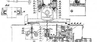
Design and operation of the machine model 3G71M and its main components
Cross caliper
The cross support is a casting with mutually perpendicular guides: the lower ones are Y-shaped, the upper ones are flat and Y-shaped.
A hydraulic cylinder is installed between the upper guides, the rods of which are connected to the table.
To measure lateral movements, a bracket with an indicator is attached to the right wing of the caliper.
The cross feed nut bracket is attached to the lower plate of the caliper.
The left front fender has a built-in mechanism for longitudinal manual movement of the table.
Mechanism for longitudinal movement of the table
The mechanism is attached to the front left wing of the caliper, the table is moved manually by a flywheel through 4-5-1 gears. When you turn on the mechanical movement of the table, gear I must be disengaged from the table rack; to do this, you need to pull the flywheel and shaft toward you. Fixation is carried out with a spring-loaded ball.
For rigid fixation, there is a button 3, which directly presses ball 2 in the groove of the shaft. To block manual and hydraulic movement, a microswitch 6 is installed in the mechanism, which does not allow the hydraulic movement of the table to be activated until gear 1 is disengaged.
Feed mechanism
The mechanism provides:
- Automatic cross feed of the caliper
- Manual cross feed
- Accelerated movement of the caliper
- Automatic vertical feed of the grinding head for each longitudinal or transverse stroke of the table
- Manual vertical feed
- Faster movement of the grinding head
Automatic cross feed occurs at the moment of longitudinal table reverse due to the supply of a current pulse to an electric motor connected through gears to the cross feed screw. The feed amount is changed by turning the switches on the control panel. One makes a rough adjustment of the transverse feed, while the other makes a fine adjustment.
When working with automatic cross feed and with accelerated movement of the caliper, flywheel 3 must be disconnected from gear 5 using a button, and gear 5 must engage with gear 1.
For manual cross feed, gear 5 must be in mesh with gear 2.
Fine transverse feed is carried out through bevel gears 4 with a button located through the upper surface.
The accelerated movement of the cross support is activated by a toggle switch on the control panel.
Automatic vertical feed is carried out from a bladed hydraulic cylinder 14, operating at the moment of transverse or longitudinal reverse of the table, depending on the position of the toggle switch.
A lever with a pawl 15 is attached to the cylinder axis. The pawl can slide along the valve 13 or engage with the ratchet wheel 8. The ratchet wheel 8 is attached to gear 7, which, through gear 9, transmits movement to the worm shaft of the vertical feed reducer. The amount of automatic feed is regulated by a valve 13, which covers the teeth of the ratchet wheel 8.
On the button for rotating the shutter 6 there are divisions of the amount of feed to be set.
Manual vertical feed is carried out by a flywheel 10 through a pair of gears 12-9 and a gearbox.
Fine feed is carried out by a button through bevel gears 4.
For coarse manual feed, the fine feed button must be in the upper position, bevel gears 11 in this case are disengaged.
To prevent the flywheel from rotating during accelerated movement of the grinding head, the mechanism is equipped with a microswitch, which is pressed when the gears 12 and 9 are separated by the button located under the flywheel 10, and only in this position can the rapid movement motor be turned on.
Main technical characteristics of surface grinding machine 3g71m
Manufacturer: Orsha Machine Tool Plant Krasny Borets.
The main parameters of the machine are in accordance with GOST 13135. Surface grinding machines with a rectangular table. Basic dimensions. Accuracy standards.
- Accuracy class according to GOST 8-71 – B. Roughness of the machined surface V 10
- Desk dimensions (length x width) – 630 x 200, mm
- Limit dimensions of the processed surface (length x width x height) – 630 x 200 x 320 mm
- The largest mass of the workpiece is 150 kg
- Dimensions of a standard grinding wheel – Ø 250 x 32 x 76 mm
- Electric motor power – 2.2 kW
- Total weight of the machine – 2.25 t
Modern analogues of the 3G71M surface grinding machine
- 3D711VF11 – 600 x 200, manufacturer Orsha Machine Tool Plant Krasny Borets
- 3L741VF10 – 600 x 200, manufacturer Lipetsk Machine Tool Plant
Operation of the hydraulic drive and interaction of components of the 3G71M grinding machine
The hydraulic drive of the machine is put into operation by pressing the “Start hydraulic drive” button, followed by setting the hydraulic panel valve 17 to the “Start” position. The oil flow, pumped by the vane pump 2, through the filter 4 through the pipeline 12 enters the central bore of the reversible spool 25 of the panel 17. When the spool 25 is positioned as shown in the diagram, the main flow enters the left bore and through the pipeline 18 into the hydraulic cylinder 20 of the table movement. The table moves in the direction of the arrow. Draining from hydraulic cylinder 20 occurs through pipeline 21 through throttle 14, valve II into hydraulic tank I.
The speed of movement of the table is regulated by throttle 14. The table moves to the right until the stop 19 associated with the table throws the reverse lever 23, which, through a system of levers, switches the control spool 24 to the left position. In this case, the right end chamber of the reverse spool is connected to pressure, spool 25 moves to the left, as a result of which the table reverses. Pipeline 21 becomes pressure, pipeline 18 becomes drain. The table moves in the opposite direction until the stop 22 moves the lever 23 to the reverse position.
The cycle is then repeated as described above.
Automatic vertical feed is carried out by turning on the electromagnet of the reversing spool 28.
The oil flow through pipeline 12 through the reversing spool and pipeline 27 enters the lower cavity of the torque hydraulic cylinder, from the upper cavity the oil through pipeline 26 through the spool and pipeline 29 is drained into the hydraulic tank. The flag is rotated clockwise. Through a gear system, rotation is transmitted to the vertical feed screw. The grinding head is fed vertically.
When the electromagnet is turned off, pipeline 26 becomes pressure, pipeline 27 becomes drain. The checkbox returns to its original position
Lubrication of the table guides and cross support, the vertical feed screw and guides and the cross feed screw is carried out from pipeline 13 through filter 10 and pipeline 15.
The oil consumption for lubrication of the table guides and cross support is regulated by throttle 16.
The oil supply for lubrication of the vertical feed screw and guides and the cross feed screw is turned on periodically by pressing button 9.
Excess oil coming from the table guides and cross support is drained through pipelines 7 and 8 into the hydraulic tank.
Passport 3L722A Surface grinding machine with a rectangular table and a horizontal spindle
Name of the publication: Part 1: Operation manual (3Л722А.000.000 РЭ) – 41 pages Part 2: Electrical equipment of the machine – 21 pages Part 3: Electrical diagrams – 47 pages Part 4: RG48-3D722-02 Complete hydraulic drive (РГ48-3Д722-02.00.000 РЭ ) – 46 pages Edition: —Year of publication: 1990 Number of books (folders): 4 Number of pages: 155 Cost: Negotiable Description: Complete set of documentation
Part 2: Electrical equipment of the machine1. Brief characteristics of electrical equipment2. Information about the power supply system for electrical equipment 3. Initial start-up of the machine4. Operating modes of the machine5. Machine control diagram 6. Protection, alarm, interlocks 7. Maintenance, adjustment List of machine electrical equipment elements 8. List of electrical equipment elements of the machine9. Information about the content of precious metals in the machine 10. Illustrations - Electrical circuit diagram for controlling the cross feed of the rack - Electrical circuit diagram of the thyristor starter (3L722A.859.000) - Voltage oscillogram - Functional diagram of the vertical feed - Functional diagram of the cross feed unit - Electrical circuit diagram of the T- element 101 - Electrical circuit diagram of element T-102 - Electrical circuit diagram of element T-103 - Electrical circuit diagram of element T-402 - Electrical circuit diagram of element T-403 - Connection diagram of wires of machine plug connectors - Layout of elements of the power switch (3L722A.854.040 )— Layout of elements of a thyristor starter (3L722A.859.000)— Components of the machine and their connections
Part 3: Electrical diagrams— Electrical connection diagram of the complete hydraulic drive (RG48-3D722-02) — Electrical connection diagram (3L722A, V.850.000E4) — Electrical circuit diagram of the power part— Electrical circuit diagram— Electrical circuit diagram of the power switch for controlling the stepper motor — Electrical circuit diagram for controlling the transverse feed of the rack - Electrical circuit diagram for the table and rack reverse unit (3L722A.858.000) - Thyristor starter Electrical circuit diagram (3L722A.859.000) - Connection diagram for the machine plug connectors
Part 4: RG48-3D722-02 Complete hydraulic drive (RG48-3D722-02.00.000 RE)1. General information about the product2. Main technical data and characteristics - Overall and connecting dimensions of the complete hydraulic drive RG48-3D722-023. Delivery set 4. Safety instructions 5. Composition, structure and operation of the product and its components - Electrical connection diagram of the complete hydraulic drive RG48-3D722-02 - Hydraulic circuit diagram of the complete hydraulic drive RG48-3D722-026. Installation procedure - Transportation diagram of the complete hydraulic drive RG48-3D722-02 - Hydraulic circuit diagram - Control unit 7. Typical malfunctions and methods for eliminating them 8. Certificate of acceptance 9. Certificate of preservation 10. Certificate of packaging 11. Instructions for maintenance and operation repair
Main devices and movements
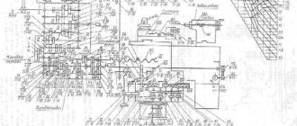
The diagram according to which the machine is assembled and its moves look like this. A column is attached to the frame. A cross support moves along the horizontal swing guides of the frame. The workbench also moves along with it, which performs longitudinal-translational moves backwards. The grinding head moves along the vertical guides of the column movement.
Kinematic diagram 3E711V
Kinematic diagram 3E711V
On the inner lower side of the support on the GS 3e711v machine the following was fixed:
- cross feed reverse block;
- reverse block for longitudinal movement of the workbench;
- workbench longitudinal reverse block;
- workbench transverse reversal block;
- distribution panel;
- hydropanel.
The grinding spindle is assembled with preload, this is facilitated by high-precision radical-thrust bearings, which are lubricated with a “non-losing” lubricant. The hydraulic station on the RGS 3e711v is equipped with a volumetric control pump. Its scheme of action is to create a smooth regulation of the speed of movement of the workbench.
Installation drawing 3E711B
Technical data and characteristics of the 3E711B machine
| Parameter name | 3G71 | 3E711V |
| Main settings | ||
| Accuracy class according to GOST 8-82 | IN | IN |
| The largest dimensions of processed products (length x width x height), mm | 630 x 200 x 320 | 630 x 200 x 375 |
| The greatest height of the processed products with the largest diameter of the grinding wheel, mm | 325 | |
| Maximum height of workpieces with smallest grinding wheel diameter, mm | 375 | |
| Distance from the spindle axis to the table mirror, mm | 80…445 | 500 |
| Maximum mass of processed products, kg | 220 | |
| Accuracy parameters maximally achieved on the sample product | ||
| Product sample size, mm | 380 x 120 x 80 | |
| flatness, µm | 4 | |
| parallelism, µm | 5 | |
| roughness of the surface processed by the periphery of the grinding wheel, Ra | 0,16 | |
| Perpendicularity of the trajectory of the transverse movement of the table to the direction of its longitudinal movement, µm | 25 | |
| Machine work table | ||
| Dimensions of the working surface of the table (length x width), mm | 630 x 200 | 630 x 200 |
| Maximum manual longitudinal movement of the table, mm | 710 | 700 |
| Speed of longitudinal movement of the table (stepless regulation), m/min | 5..20 | 2..35 |
| Table movement per revolution of the flywheel of the longitudinal movement mechanism, mm | 15,3 | |
| Table support. Table cross feed mechanism | ||
| Maximum manual lateral movement of the table / automatic, mm | 235 | 250/ 245 |
| Price for dividing the flywheel dial for transverse movement of the table, mm | 0,05 | |
| Price for dividing the micrometric feed dial for transverse movement of the table, mm | 0,01 | |
| Automatic cross feed for each table stroke (stepless regulation), mm | 0,3…4,2 | 0,3..30 |
| Accelerated movement of the table cross support, m/min | 1,5 | |
| Grinding head. Grinding wheel | ||
| Maximum vertical movement of the grinding head, mm | 365 | |
| Accelerated vertical movement of the grinding head, m/min | 0,27 | |
| Grinding wheel dimensions, mm | 250 x 32 x 76 | 250 x 40 x 76 |
| Grinding wheel revolutions per minute | 2740 | |
| Highest cutting speed, m/s | 35 | |
| Dividing value of the vertical movement flywheel dial, mm | 0,001 | 0,002 |
| Fine vertical feed dial division price, mm | 0,0005 | |
| Automatic feed of vertical movement (stepped in increments of 0.005), mm | 0,005…0,05 | – |
| Automatic feed of vertical movement (stepped in increments of 0.002), mm | – | 0,08..0,002 |
| Electrical equipment and machine drive | ||
| Number of electric motors on the machine | 5 | 7 |
| Grinding wheel spindle drive electric motor, kW | 2,2 | 4 M1 |
| Electric motor for table hydraulic drive, kW | 1,1 | 3.0 M2 |
| Electric motor of the oil cooling fan in the hydraulic station, kW | – | 0.09 M3 |
| Cross feed drive electric motor, kW | – | 0.18 M11 |
| Electric motor for accelerated movement of the grinding head, kW/rpm | 0,18 | 0.55 M8 |
| Cooling pump electric motor, kW/rpm | 0,125 | 0.15 M6 |
| Magnetic separator electric motor included with the unit, kW | 0,08 | 0.12 M7 |
| Total installed power of all electric motors, kW | 3,685 | 8,09 |
| type of supply current | 50Hz, 380/220V | 50Hz, 380V |
| Dimensions and weight of the machine | ||
| Machine dimensions (length x width x height), mm | 1870 x 1550 x 1980 | 2000 x 1770 x 1920 |
| Machine weight, kg | 2000 | 2550 |
Bibliography:
Surface grinding machines 3E711VF1, 3E711AF1, 3E711V, 3E721VF1-1, 3E721AF1-1, 3E721V-1, 3E711V-1, 3E710A. Operating manual, 1978 Surface grinding machine 3E711B. Manual. Electrical equipment, 1983
Alperovich T.A., Konstantinov K.N., Shapiro A.Ya. Design of grinding machines, 1989
Alperovich T.A., Konstantinov K.N., Shapiro A.Ya. Setup and operation of grinding machines, 1989
Dibner L.G., Tsofin E.E. Sharpening machines and semi-automatic machines, 1978
Genis B.M., Doctor L.Sh., Tergan V.S. Grinding on cylindrical grinding machines, 1965
Kashchuk V.A., Vereshchagin A.B. Grinder's Handbook, 1988
Kulikov S.I. Honing, 1973
Lisova A.I. Design, adjustment and operation of metal-cutting machines, 1971
Loskutov V.V. Metal grinding, 1985
Loskutov V.V. Grinding machines, 1988
Lurie G.B. Grinding machines and their adjustment, 1972
Lurie G.B. Design of grinding machines, 1983
Menitsky I.D. Universal sharpening machines, 1968
Mutsyanko V.I. Bratchikov A.Ya. Centerless grinding, 1986
Naerman M.S., Naerman Ya.M. Guide for training grinders. Textbook for vocational schools, 1989
Popov S.A. Grinding work, 1987
Tergan V.S. Grinding on cylindrical grinding machines, 1972
Shamov B.P. Types and designs of main components of grinding machines, 1965
Related Links. Additional Information
Home About the company News Articles Price list Contacts Reference information Download passport Interesting video KPO woodworking machines Manufacturers
Technical characteristics of the 3D711VF11 machine
The technical characteristics of the 3D711VF11 machine are the main indicator of the suitability of the machine for performing certain work on machines. For surface grinding machines, the main characteristics are:
- Table work surface size
- The largest dimensions of the sanded product
- Circle speed
- Table longitudinal movement speed
Below is a table with the technical characteristics of the 3D711VF11 surface grinding machine. More detailed technical characteristics of the machine can be found in the passport of the 3D711VF11 machine located below.
| Name of parameters | Unit. | Quantities |
| Machine accuracy class according to GOST 8-82 | IN | |
| Largest dimensions of the workpiece (LxWxH) | mm | 990x280x375 |
| Weight of the installed workpiece, no more | kg | 220 |
| Outer diameter of grinding wheel | mm | 300 |
| Internal diameter of grinding wheel | mm | 76 |
| Maximum height of grinding wheel | mm | 63 |
| Minimum height of grinding wheel | mm | 40 |
| Working surface of the table (LxW) | mm | 630x200 |
| Number of T-slots | 3 | |
| Groove width | mm | 14 |
| Distance between grooves | mm | 50 |
| Table mounting surface (LxW) | mm | 990x200 |
| Distance from the spindle axis to the table mirror | mm | 550 |
| Maximum manual table movement | mm | 700 |
| Maximum manual movement of the caliper | mm | 250 |
| Spindle speed | rpm | 2230 |
| Working table feed | m/min | 2…35 |
| Caliper working feed | m/min | 0,3…40 |
| Automatic vertical roughing feed (stepped) | mm | 0,01…0,09 |
| Automatic vertical finishing feed (stepped) | mm | 0,001…0,009 |
| Speed of rapid movements of the caliper | m/min | 2,14 |
| Speed of rapid movements of the grinding head | m/min | 0,3 |
| Main drive power | kW | 4 |
| Dimensions of the machine without separately located units (LxWxH) | mm | 2595x1775x2035 |
| Weight of the machine without separately located units | kg | 2300 |
| Weight of separately located units and electrical equipment | kg | 650 |
Attention! The technical specifications given in the above table are for reference only. Machines produced by different manufacturers and in different years may have characteristics that differ from those given in the table
Manufacturer information
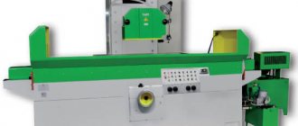
The 3E711B surface grinding machine is manufactured in Orshansk at the Krasny Borets machine-tool plant.
The plant was founded more than a hundred years ago. And the surface grinding machine began to be produced only 60 years after its discovery. The first metal cutting machine, 3711, whose characteristics were distinguished by high-precision indicators, was released in 1967. And the universal surface grinder GS 3E711V has become a successful replacement for the old version 3G71.
General view of the grinding machine 3E711B
Surface grinding machine 3l722v technical characteristics
File Description
- Data sheet for a surface grinding machine with a rectangular table and a horizontal spindle
- Maud. 3L722A, 3L722V, 3L722V-70, 3L722V-80, 3L722V-001, 3L722V-002
- Lipetsk Machine Tool Plant (LSPO)
1990 - 3L722V_3L722A_3L722V-70.djvu (13.57 MB)
1991 - 3L722A_3L722V.djvu (8.96 MB)
Manual. Electrical equipment. Electrical circuit diagrams - 3L722A_3L722V_Elektrooborudovanie.djvu (6.61 MB)
Drawings and diagrams – 3L722V_big.djvu (2.02 MB)
Download the passport and electrical diagrams of this machine from another plant (Leningrad):
Surface grinding machine 3L722V with a rectangular table and a horizontal spindle
- Surface grinding machines with a rectangular table and a horizontal spindle, model 3L722V, accuracy class “B” according to GOST 8-82, are designed for processing the surfaces of parts with the periphery or end of a grinding wheel, various shaped surfaces of workpieces with a profiled wheel.
- The layout of the machine in combination with the spindle design ensures high rigidity of the grinding headstock and eliminates the influence of the mass of moving components on the accuracy and quality of processing.
- A digital display device for visual control of the amount of movement of the grinding headstock and a remote control system can improve the productivity of the machine and ease of maintenance.
- A remote hydraulic drive with an oil temperature stabilization system and a centralized lubrication system reduce thermal deformation, increase the durability of the machine and help maintain the accuracy of the machine during long-term operation
Machine 3L722V. Surface grinding. Specifications
Technical characteristics of machines are the main indicator of the suitability of the machine for performing certain jobs on the machine. For surface grinding machines, the main characteristics are:
- Dimensions of the working surface of the machine
- The largest dimensions of the sanded product
- Table longitudinal movement speed
- Circle speed
Below is a table with the technical characteristics of the 3L722V surface grinding machine. More detailed technical characteristics of the machine can be found in the passport of the 3L722V machine, which can be downloaded below.
The best welding inverter for home
- Machines models 3L722V(A), 3L722V(A)-70, 3L722V(A)-80, 3L722V(A)-M designed for grinding the end and periphery of a circle of flat and shaped surfaces of workpieces made of magnetic and non-magnetic materials.
- Option Option Option
- —>
Submit your application
- Description
- Characteristics
- Equipment
- Special offers
Machines series 3L722
(V(A), V(A)-70, V(A)-80 and V(A)-M), which are analogous to models 3L722V, 3B722 and 3D722, have a special range of application.
Surface grinding machines with a rectangular table 3L722 are used for grinding shaped and flat surfaces of those workpieces made of magnetic and non-magnetic raw materials, using the end or periphery of a wheel.
Fastening of the workpieces (in accordance with their dimensions, shape and material) can be carried out either in a special device or on an electromagnetic plate.
Using a number of kinematic chains, the 3L722 machine
capable of performing the following movements:
- rotate the spindle of the grinding head;
- move the grinding head vertically;
- move the stand transversely;
- move the table lengthwise.
- Rigidity and resistance to vibration, which characterize the 3L722 surface grinding machine
, allow you to process flat surfaces with high precision and cleanliness.
The design of this type of surface grinding equipment has a spindle on high-precision roller bearings. With the help of a ball screw, the grinding head moves in the vertical direction, and the stand moves in the horizontal direction. The fluoroplastic coating, which guides the movement of the rack table, increases the service life of the body parts.
The level of permissible load on the table is quite high, making it possible to process even heavy parts. The design of this equipment is provided with a centralized lubrication system, and can also be equipped with a one-axis or two-axis display.
Specifications
Main characteristics of the IT-1M lathe:
- The maximum diameter of the workpiece depends on the location: directly above the bed - 400, above the recess - 550, above the support - 225.
- In the recess, the maximum processing length is 30 cm.
- The diameter of the rod passing into the spindle hole is 36 mm.
- The number of gears to switch spindle speeds is 12.
- The workpiece length limit is 140 cm.
The machine provides rotation in forward and reverse directions. The main drive of the unit has a power of 3 kW and a rated speed of 1410 rpm. Processing accuracy is normal (N).
Features of the electrical circuit
The electrical circuit of this machine is as follows. The supply voltage is supplied by a copper wire (cross section 4 mm2). The power wires enter through a flange elbow located on the wall of the electrical cabinet on the right. The input wiring is led to a terminal block located on the wall of the electrical cabinet on the right. Then they are connected to the input block of the AK63-3M type circuit breaker. This electrical circuit is quite complex.
Electrical diagram 3E711B
The following is used on the machine:
- Power circuit -380 V.
- Control circuit -110 V; 29 V. DC indicator -24 V.
- Local lighting circuit – 24 V.
- Signaling circuit - 22 V.
- Electromagnetic tile circuit (constant indicator) -110 V.
Design features of the machine
The main purpose of the 3G71 machine is grinding various parts and workpieces using special abrasive wheels. The process occurs with a spindle on which the abrasive is located. Changing the position of the part can occur due to the displacement of the work table and spindle head.
Basically, machining is carried out by contacting the periphery of the wheel with the workpiece being processed. With the help of special devices it is possible to change the angle up to 90°. However, to do this, you must purchase components that are not included in the standard equipment package.
The design and operational characteristics of the machine include the following:
- the electromagnetic plate ensures a stable position of the workpiece during processing;
- independent mechanisms for moving the work table and grinding head. The kinematic diagram of the latter is based on rolling guides;
- convenient location of feed response devices. They are located at the bottom of the worktable support. The control unit for the coolant supply system is also located there.
The control components are located in a separate block, which is installed on the right side of the equipment. During operation of the 3G71 machine, access to it remains free, regardless of the operating mode and position of the work table.
When installing additional components, it will be possible to perform profile grinding of workpieces. However, before this, it is necessary to agree on the dimensions and mounting locations of the device.
Important characteristics of grinding machines
You can buy different grinding machines depending on the processing of the required type of parts, but one way or another, when choosing them you will have to pay attention to some technical characteristics
- Firstly, it is the drive power.
- Secondly, the distance from the work table to the spindle axis, which affects the thickness of the workpiece.
- Thirdly, the worktable travel along the X and Y axes, which provides the grinding length and width.
In addition, important characteristics of grinding machines are processing accuracy, minimum and maximum transverse feed and, of course, the size of the work table
It is these technical characteristics that you need to pay attention to first.
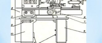
3g71 surface grinding machine
The 3g71 machine is used to perform various surface grinding tasks. Grinding mainly occurs at the periphery of the wheel. Under certain conditions, you can grind surfaces located at right angles to the table mirror. With the use of specialized devices, the functionality of the machine is expanded.
Including, when giving the abrasive wheel a given profile, profile grinding can also be carried out. A magnetic table and special devices are used to secure parts.
Figure - 3g71 surface grinding machine
Accommodation requirements
To realize the high accuracy of the machine, there are special requirements for its placement:
- Work must be carried out in a room with an air temperature of 16...20°C, sudden temperature changes should not exceed 1.5°C.
- The machine should be protected from external vibration influences
- The required accuracy of machine installation in the transverse and longitudinal directions is 0.02 mm per 1 m
Kinematic diagram
Rotational motion is transmitted to the spindle from a separate electric motor. Cross feeding can be done either manually or automatically. Longitudinal feed is also set in manual or automatic mode.