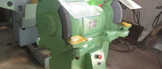
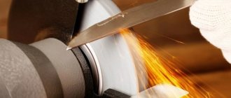
Description
This turning and grinding device was produced at the machine tool plant in Orsha. Immediately after the start of production, it was noted that the unit was relatively inexpensive and met all the standards of that time. Later, the device also demonstrated good reliability and durability in use. Even today, repairing a unit and replacing its key components is relatively inexpensive.
In addition, the machine is distinguished by its versatility compared to other devices of its class. It is widely used in various areas of production and to perform various works, which include:
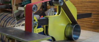
- Polishing parts (after replacing the wheel).
- Chamfering, grinding and processing of metal parts.
- Sharpening and grinding of drilling and turning tools.
- Sharpening of any metalwork tools.
It is noteworthy that this device is often sold complete with a special vacuum cleaner that cleans work surfaces of industrial waste. Based on the technical and functional features of the machine, it is most often used in small enterprises, but it can also be found in home workshops.
It is worth noting that for home use this unit may be too powerful or too large.
Information about the manufacturer of the Universal-V lathe
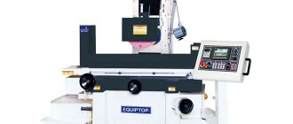
The Universal-V (TSh3-01) desktop multifunctional lathe was produced at the Votkinsk Machine-Building Plant , founded in 1759.
Metal-cutting machines at the Votkinsk Machine-Building Plant have been produced since 1956. These are vertical milling machines 6N13 , VM127 , VM127M , universal milling machines VM130 , VM133 , horizontal milling machines with CNC VM500PMF4 , VM501PMF4 , as well as a table lathe Universal-V .
Currently, JSC Votkinsk Plant is the leading enterprise of the rocket and space complex and a manufacturer of a wide range of civilian products.
Machine tools produced by the Votkinsk Machine-Building Plant
- 6N13P
- vertical cantilever milling machine, 400 x 1600 - 6R13F3
- vertical cantilever milling machine with CNC, 400 x 1600 - 6Р13рФ3
- vertical cantilever milling machine with CNC, 400 x 1600 - VM127
- vertical cantilever milling machine, 400 x 1600 - VM127M
- vertical cantilever milling machine, 400 x 1600 - VM-130
- wide-universal milling machine, 250 x 630 - VM501PMF4
- horizontal milling machine with CNC and ASI, Ø 250 - Universal-V
- tabletop screw-cutting lathe, Ø 150
Design features
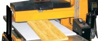
The TSh 3 machine, at first glance, is similar to its predecessor models - the TSh 1 and TSh 2 machines. The machine has a classic layout - an electric motor is installed on the bed, which drives the working shaft.
Each of the grinding heads, which are mounted on the shaft, has protective devices with a through hole for installing the elements being processed. Fixation of workpieces is carried out using special platforms, which are located near each working unit.
Other design features of the machine include:
- To protect the operator from production waste, transparent shields are installed above the working areas.
- The design of the device includes a lamp to illuminate the work area.
- Dimensions allow the device to be installed in small spaces.
- A special relay blocks engine operation if the permissible load is exceeded.
- Extreme rigidity of the frame is ensured by special metal sheets with stiffeners.
- The bed is designed in such a way that the operator has the ability to control the parameters of the working area.
- The height of the machine allows you to work on it even without a workbench, but before installing the machine on the floor, you should check its levelness and accuracy.
Key changes in the design of the machine, compared to previous models in this line, were made to increase operator safety and simplify his work with the machine. The materials from which the key components of the unit are made significantly increase the durability of its operation.
Precautions when working with equipment
- Conscious adherence to safety measures during operation, as well as during transportation and installation indoors.
- In the electrical circuit, ensure the serviceability of the emergency de-energization device.
- The workroom should be equipped for fire protection.
- Place emergency medical supplies and medications within easy reach.
- Work clothes should be adjusted so as to prevent accidental contact with rotating mechanisms.
The prototype of the new screw-cutting lathe MetalMaster -1830 remains the TSh-3 model of the machine even before the perestroika, Soviet brand Universal - 3. It looks aesthetically pleasing, is equipped with a smooth drive control, and is equipped with electronics. And, most importantly, the machine has made a qualitative transition from an amateur machine to the category of a professionally advanced machine for metalworking.
Machine structure
The figure shows the key components of the unit.
- Device drive.
- Bed.
- Spindle head.
- Caliper.
- Rear grandma.
- Electrical equipment.
It is worth talking in more detail about the electrical equipment of the unit. The operator is protected from electric shock by means of working insulation and a ground wire. The electrical equipment is located in a special box at the back of the device. The box closes tightly using a lid with two screws, one of which serves as a grounding connection.
There is a cylindrical type guide on the frame, which, together with the flat frame guide, is the basis for the main mechanisms of the device. On the left side of the headstock there is a bracket to which the machine drive electric motor is attached.
Under the protective casing of the bracket there are elements of the rotation drive and feed drive. Under the casing of the front part of the frame there is a screw for moving the caliper (longitudinal).
Description of the operation of the electrical circuit of the Universal-V lathe
Electrical equipment is powered from a single-phase alternating current network with a voltage of 220 V and a frequency of 50 Hz.
Starting and stopping the electric motor is carried out using the KV relay (see Fig. 14), which is controlled by the SB2 (start) and SB1 (stop) buttons. When starting, the KV relay turns on and becomes self-powered, connecting the electric motor to the network with its contacts and providing zero protection, i.e. turning off the electric motor when there is no voltage in the network. The electric motor is protected from overload by the start-up relay A, which breaks the starting circuit, which turns off the KV relay. Restarting is possible only after 15-50 s, i.e. after the thermal protection elements of the start-up relay A return to their original position.
When starting the electric motor, its starting torque increases due to the connection of the starting capacitor C1 by the contacts of the start-protective relay A in parallel with the running capacitor C2. After the electric motor accelerates and the starting current decreases, capacitor C1 is turned off.
Reversing the electric motor is carried out using the switch SA, which, with the middle (vertical) position of the handle, ensures that the electric motor is turned off, i.e. it stops even when the KV relay is turned on. The handle should be left in a neutral position
System and controls
Key control units are shown in the diagram.
- Handle for adjusting the feed movement. With its help you can activate the caliper and select the direction of its movement.
- Main movement adjustment knob. Activating the forward or reverse movement of the spindle stops its operation.
- Handle for moving the caliper (transverse).
- Handle for moving the tool holder.
- Handle for fixing the quill.
- Handle for moving the caliper (longitudinal).
Features of the TSh 3M unit
The machine for turning and milling work, model TSH3, is made according to a classical layout. The list of functional units and parts includes:
- a frame that forms the rigidity frame of the unit;
- headstock with spindle clamping block;
- tailstock block with quill fixation unit;
- support for installing the main working body;
- electrical equipment unit.
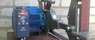
The drive system includes an electric motor that transmits torque through a pulley. The connection diagram is standard: using a cable and a plug.
The engineering solution of the TSh 3M machine, which distinguishes it from other units of the same class, is the design of the bed. It includes metal sheets equipped with stiffening ribs, which made it possible to achieve optimal strength indicators with a low final mass of the unit.
Design Features
Compared to its predecessors, models TSh1, TSh2, the TSh3M machine received many additional components and technical measures designed to protect the operator and allow him to better control the working area and the quality of the operation being performed. The list of equipment features includes:
- shields made of transparent plastic, glass, protecting against the emission of chips and abrasives;
- work area lighting lamp with variable position;
- motor protective relay, blocking the transfer of power to the drive pulley wheel during overload.
The design is characterized by a high level of convenience, good visibility of the working area, comfortable positioning of the operator and the performance of various actions. This is achieved through a thoughtful arrangement of the functional units of the machine on the bed.
The design of the grinding head block has been modified. Installation of the working element is simple; in most cases, fixing it is enough to tighten one screw. However, to increase safety, each head is equipped with protective devices, and rigid positioning of the workpieces is carried out by the platforms of the working unit.
Specifications
The characteristics of the TS3 model are as follows:
- technological mass (machine without installed head block) - 220 kg;
- dimensions 660x600x1370 for height, depth along the drive block, width, respectively;
- seat diameter of wheels for grinding or sharpening - 127 mm;
- the maximum diameter of circles that can be used on the device is 400 mm;
- power supply 380V, three phases;
- electric drive power 3 kW;
- nominal cutting speed 20 mm/s.
The machine drive is equipped with a speed stabilization system and, under normal load, ensures rotation of the spindle chuck at a speed of 950 rpm.
Operating rules
The operating rules for the TSh3 machine include both a basic set of actions and some requirements determined by the design features of the equipment.
- The installation method and support for the machine must ensure rigidity and prevent displacement and resonant vibrations.
- Equipment grounding is mandatory.
- You should start working with parts only after the shaft has accelerated to the rated rotation speed.
- Installation of the machine in rooms with a designated level of explosion hazard, as well as when flammable substances are stored in them, is not allowed.
- The rests should not be installed higher than 10 mm of the directrix of the grinding wheel axis.
- The minimum gap between the workpiece and the abrasive wheel should not be less than 3 mm, and should not exceed half the thickness of the object.
When operating the machine, the list of mandatory measures includes (before its start-up) checking the grounding, the condition of the power cable and plug, the reliability of fastening of casings, working parts, and accessories. The serviceability is tested by starting the unit in idle mode for 5 minutes.
Personnel without special permission, qualifications, or profession are not allowed to work with TS3. The use of overalls (trousers, overalls with long sleeves and tightly buttoned cuffs), including a protective beret and glasses, is mandatory. Upon completion of the work, the dust collector, frame, and other structural elements are cleaned from dirt, dust, and metal shavings.
Technical indicators
The scope of application and class of the device are determined by its main technical characteristics. The dimensions of the machine also play an important role. This machine has the following dimensions:
- length – 137 cm;
- height – 60 cm;
- width – 60 cm;
- weight – 220 kg.
The maximum outer diameter of the machine's grinding wheels is 40 cm. The inner diameter of the grinding wheel is 12.7 cm. The working shaft of the unit rotates at a speed of 950 rpm. The maximum cutting speed is 20 mm per second. The power of the electric motor is 3 kW.
Technical characteristics of the Universal-V machine
| Parameter name | Universal-B |
| Basic machine parameters | |
| The largest diameter of the workpiece above the bed, mm | 150 |
| The largest diameter of the workpiece above the transverse guides of the caliper, mm | 90 |
| Maximum length of the workpiece at centers (RMC), mm | 250 |
| Recommended turning depth per pass, mm | |
| Maximum turning depth in one pass, mm | |
| Maximum cutter holder size, mm | 8 x 8 |
| Largest drilling diameter for steel, mm | 6 |
| Headstock. Spindle | |
| Diameter of through hole in spindle, mm | 15 |
| Cone in the headstock spindle | Morse 2 |
| Attaching the chuck to the spindle | M27 |
| Number of speed steps for direct spindle rotation | 9 |
| Spindle direct rotation frequency, rpm | 200..3200 |
| Diameter of the product clamped in the chuck, mm | 4..70 |
| Stroke of the headstock sleeve, mm | 30 |
| Caliper (transverse slider). Submissions | |
| Maximum longitudinal movement of the caliper carriage, mm | 215 |
| Longitudinal movement of the caliper by one dial division, mm | 0,05 |
| Maximum lateral movement of the caliper, mm | 90 |
| Transverse movement of the caliper by one division of the dial, mm | 0,05 |
| Maximum movement of the cutting slide (upper support, composite slide), mm | |
| Angle of rotation of the cutting slide, degrees | |
| Limits of longitudinal working feeds of the caliper, mm/rev | 0,05..0,175 |
| Limits of pitches of cut metric threads, mm | 0,2..2,5 |
| Limits of pitches of cut threads, inch, threads per inch | |
| Tailstock | |
| Maximum movement of the quill, mm | 30 |
| Tailstock cone | Morse 2 |
| Electrical equipment | |
| Rated supply voltage, V | 220V 50Hz |
| Main drive DC motor, kW | 0,37 |
| Dimensions and weight of the machine | |
| Machine dimensions (length width height), mm | 690 x 410 x 230 |
| Machine weight, kg | 62 |
- Tabletop machine Universal-V (TSh3). Operating manual, 1992
- Acherkan N.S. Metal-cutting machines, Volume 1, 1965
- Batov V.P. Lathes., 1978
- Beletsky D.G. Handbook of a universal turner, 1987
- Denezhny P.M., Stiskin G.M., Thor I.E. Turning, 1972. (1k62)
- Denezhny P.M., Stiskin G.M., Thor I.E. Turning, 1979. (16k20)
- Modzelevsky A. A., Muschinkin A. A., Kedrov S. S., Sobol A. M., Zavgorodniy Yu. P., Lathes, 1973
- Pikus M.Yu. A mechanic's guide to machine repair, 1987
- Skhirtladze A.G., Novikov V.Yu. Technological equipment for machine-building industries, 1980
- Tepinkichiev V.K. Metal cutting machines, 1973
- Chernov N.N. Metal cutting machines, 1988
Bibliography:
Related Links. Additional Information
- School lathes
- Manufacturers of lathes
- Classification and main characteristics of turning
- Selecting the right metalworking machine
- Multi-start thread. Methods for cutting multi-start threads on a lathe
- Graphic signs for lathes
- Friction clutch of a screw-cutting lathe
- Methodology for checking and testing screw-cutting lathes for accuracy
- Lathe spindle ends
- Lathe chucks. Varieties, features of selection and operation
- Directory of lathes
Home About the company News Articles Price list Contacts Reference information Interesting video KPO woodworking machines Manufacturers
Tips for use
Before starting to operate the unit, you should check the grounding of the machine and the condition of the protective covers. Particular attention must be paid to the serviceability of the electrical cable and plug. Before starting to process parts, let the machine run for a few minutes in idle mode.
When working with the device, adhere to the following recommendations:
- The play between the grinding wheel and the workpiece should be half the thickness of the object.
- The unit should be installed on the floor or a special workbench, taking into account the weight of the machine. The device must stand securely and not wobble, otherwise it will negatively affect the accuracy of workpiece processing.
- The parts to be turned should be placed above the horizontal line that passes through the center of the grinding wheel. Handles are installed taking into account this need.
- The machine operates from a three-phase network with a voltage of 380 V.
- You cannot start working on the unit if it has grounding problems.
- The bed and other components of the device require regular maintenance and cleaning from production waste.
- When working with the machine, you should wear safety glasses and appropriate clothing.
- There should be no explosive materials or flammable substances in the room where the machine is installed.
- A device with damaged or inoperative components must not be used under any circumstances.
- You should start working with the workpiece only after the main shaft has been fully untwisted. Otherwise, the operator risks causing damage to himself or the machine.
Video: review of the TSH-3 lathe.
Precautions when working with equipment
- Conscious adherence to safety measures during operation, as well as during transportation and installation indoors.
- In the electrical circuit, ensure the serviceability of the emergency de-energization device.
- The workroom should be equipped for fire protection.
- Place emergency medical supplies and medications within easy reach.
- Work clothes should be adjusted so as to prevent accidental contact with rotating mechanisms.
The prototype of the new screw-cutting lathe MetalMaster -1830 remains the TSh-3 model of the machine even before the perestroika, Soviet brand Universal - 3. It looks aesthetically pleasing, is equipped with a smooth drive control, and is equipped with electronics. And, most importantly, the machine has made a qualitative transition from an amateur machine to the category of a professionally advanced machine for metalworking.
Important nuances
Like any other mechanisms, the components of this machine can fail. Here are the most common breakdowns and approximate ways to fix them:
- If the bearings in the machine are knocking, they should be replaced as soon as possible. By continuing to operate the machine with faulty bearings, you jeopardize the performance of other machine components.
- The motor makes too much noise or gets hot quickly. In this case, it is necessary to monitor the condition of the motor winding or completely replace it.
- The reason for the sudden stop of the motor may be a malfunction in the electrical network or problems with the starting mechanism.
- A malfunction of the electric motor is also indicated by its inability to reach full speed. This often happens due to problems with the electrical supply or due to a motor failure. If a problem with the electrical network constantly interferes with work, you should purchase a special stabilizer. If the engine itself is faulty, then it will have to be replaced.
It is not recommended to disassemble the machine yourself unless absolutely necessary. But if a breakdown is discovered and you are sure that you can fix it, then before disassembling the machine it should be completely disconnected from the power supply. After this, disassemble the problem unit and try to fix the damage.
Remember that it is much easier to prevent breakdowns than to fix them! To increase the service life of the machine, adhere to the following recommendations:
- Follow all instructions for using the machine.
- Clean the main components of the unit regularly and in a timely manner.
- Check the condition of the electrical network and electrical equipment of the machine.
- Lubricate all running parts of the device in a timely manner.
Republished by Blog Post Promoter
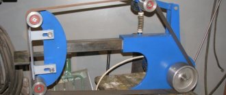
TS-3, will you accept a newcomer into your ranks?
Hi all! In the evening I finished struggling with the balcony lighting and started disassembling my machine. The problems voiced by the respected John Do in full! After removing the protection, I saw the curvature of the drilling and the bent ears of the protection. The defense is really on point. Inspection of the screw showed its curvature with the apex of the joint. In order to exclude erroneous versions, it was decided to remove the lead screw. Just like I said
anrkaid, the thread is really 14. I tightened two symmetrical bolts and nuts. I knocked out one of the pins (the drift from the standard VAZ set, which was inserted into the holes of the spark plug key like a wrench, worked very well). I removed the longitudinal movement flywheel and unscrewed the washer. Removed the back of the screw. At this stage, something interfered with the tailstock, unscrewing two bolts from the front from below and the bolt securing the rear part (sorry, I’m not strong in terms, maybe it has some name), calmly tilted it towards itself, unscrewed the bolt of the fixing lever with a screwdriver, and removed his. The axis of this lever is a bolt. I unscrewed it and separated the lower part. The grandmother has been removed. I removed the screw without any problems. Having loosened all the bolts, I realized that the reason was still a pair of nuts and screws. Time still allowed and it was decided not to stop there. By moving the caliper back the cartridge was removed. Next up is the pulley and engine. Removing the pulleys did not cause any difficulties; everything came off easily. When trying to disconnect the engine, pay attention to the far lower bolt - it is a tension bolt. By unscrewing the locking plate of this screw, it was easily removed. After this we were able to remove the engine. Next is the second pulley. Then the feed gear block, without disassembling, together with the base. I unscrewed three bolts and removed the casing along with the lower pulley. There was a noticeable roll on the spindle, the bearings were unloaded and noisy and needed to be replaced. Removing the spindle is also simple and intuitive, with six bolts, three on each side, and a nut. On my machine, the spindle is mounted on two 7206A angular contact roller bearings with tapered rollers. Used in the steering of Soviet buses and in the front hubs (internal support) of MOSKVICH 2140. The remaining grease in the bearings has turned into hard pieces of an abrasive mixture and don’t understand what else. The greatest difficulty was caused by the next and last unit, the gear unit for switching the feed direction (I can’t vouch for the correctness of the name). Snagging was detected when this gear block rotates, but I will deal with this a little later. It was possible to unscrew the front nut only by breaking the pin under the large gear. The gear has been removed, then the shift bracket (visually, it feels like it has a bend). There were no problems with removal. On a large black washer with three gears, a threaded stopper was noticed, it was unscrewed, there was a groove on the washer for a screwdriver, when you tried to move the washer there was play, but it did not come out. Stopped in time. I noticed that the round guide moves slightly. Released the rear screw. The guide moved out along with the gear block. There is another threaded stop on the guide; it can only be seen by pulling out the guide. By the way, the front bolts securing this guide were completely loosened. The machine is disassembled. In the coming days, an inspection of the cartridge, gears, and an engine check.
PS As Nikolay said, the equipment is really decent, one of the reasons for buying this particular copy.