The rotating spindle head of the machines is equipped with a mechanism for manual axial movement of the spindle sleeve, which allows processing of holes whose axis is located at an angle of up to ±45° to the working surface of the table. The drive power and high rigidity of the machines allow the use of cutters made of high-speed steel, as well as tools equipped with plates made of hard and super-hard synthetic materials.
The 6P13 vertical milling machine differs from the similar 6P12 machine in the installed power of the main movement and feed motors, the dimensions of the working surface of the table and the amount of table movement.
Design features:
- mechanized tool fastening in the spindle;
- proportional feed deceleration mechanism;
- a device for periodically adjusting the size of the gap in the longitudinal feed screw pair;
- safety clutch protecting the feed drive from overloads;
- braking of the horizontal spindle when stopping using an electromagnetic clutch;
- protection device against flying chips.
- various automatic work cycles;
- wide range of spindle speeds and table feeds;
- high drive power;
- high rigidity;
- reliability and durability.
Technological features:
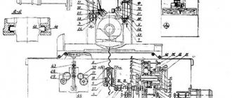
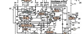
Kinematic diagram
The kinematic diagram of the equipment is quite standard in appearance; it is necessary for the engineer to understand the general scope of the work and the connection of structural parts. Judging by it, you can understand how movement is transmitted from one node to another and why the characteristics change and the like.
The drive is powered by a flange electric motor. They are connected using a high-quality coupling. Spindle revolutions per minute can be a different number. This characteristic is controlled using three gear blocks. They are located along the shafts, which can be easily seen in the kinematic diagram. The gearbox gives the desired display to the spindle. The device's operating sheet states that there can be a total of 18 speeds.
Please note that:
- feed drive from the engine, which is located on the console;
- accelerated movements are made by the high speed clutch;
- friction clutch works by means of gears;
- the feed clutch is connected to the clutch;
- the clutch and clutch can be turned on simultaneously, since they are connected.
The kinetic diagram indicates the basis, the main part is the frame. It is fixed with pins on the base of the machine.
Location of components
The cantilever milling installation includes the following set of main components:
- Electrical cabinet
- Crawler.
- A mechanism that lubricates the console and work surface.
- Earring.
- Rotary, milling head type.
- Fencing.
- Work table.
- The part with the console.
- Cooling system.
- Drive part of the spindle.
- Gearbox.
- Bed.
- Equipment with electrical parts.
- Boxes that control reverse, feed, speed.
The bearings become the main support for the spindle. The part itself is located inside the sleeve. A special neck, also called centering, is placed on the rotary heads. Thanks to this, there are no problems when installing the head on the bore of the frame, when the parts themselves are installed on the unit.
The machine is easier to operate when using handles. They perform several functions at once:
- Different types of feeds are turned on and off.
- Switching searches, speeds for units with a spindle.
- Using special modes.
- Starting the manual lubrication pump.
Additional feed is started by several buttons included with the machine. The spindle and stop work the same way. There are other control components:
- Additional devices responsible for the cooling pump and regulation of the amount of liquid.
- A square that turns the head, moves it, and helps secure the trunk.
- Light switches.
- Flywheels that move the table manually.
- What turns off the cooling pump.
Description of the mechanism
As mentioned above, the machine is equipped with software that allows:
- carry out diagnostics and ensure performance;
- install new and remove existing programs and even edit their data if necessary;
- configure the chain of required functionality commands;
- fully control the operating process of the unit;
The software allows you to control the functioning of the entire work process, from the start of finishing work to completion. Using the software, the operator receives information about all errors and breakdowns, other system parameters, basic information regarding the operation, as well as additional information. You can view information about installed software and, if necessary, install new software or change functionality.
This software is only part of the entire electrical equipment of a vertical milling machine. Its operation is provided by a three-phase electrical network with a voltage of 380 volts. The control elements are equipped with a protection mechanism. Operation can also be ensured with the help of special machine converters and even stabilizers. This protects the device from damage due to electrical voltage surges.
The control station is started by the introductory automatic machine. Its operation is controlled by handles and built-in levers located on the outside of the equipment.
The device operates normally at voltages:
- 110 volts - main operating circuits;
- 55 volts - the circuit that controls the stop of the router;
- 48 volts - motor;
- 24 volts - main lighting;
- 380 volts is a power circuit that has three phases.
The feedback operates using a generator, and the speed - a tachogenerator built into the electric motor.
Equipment and accessories
All parts of the mechanism are bimetallic and replaceable. The machine is equipped with a milling table 1600 * 400 mm. A protective edge around the perimeter of the working area increases operator safety during operations accompanied by strong scattering of chips. The height of the sides is adjusted manually. The spindle is installed in a retractable sleeve and is deflected along the main axis thanks to the rotating head. In order to increase the rigidity of the machine, mechanical clamps are used.
Machine equipment:
- Automatic transmission;
- speed controllers;
- working head;
- spindle;
- collet chuck;
- gearbox;
- ball screws;
- elastic couplings;
- friction shafts;
- brake clutch.
The machine allows you to use a round rotary table, install a dividing head and work on markings. The end mill chuck can be exchanged for an arbor for face and disc cutting.
Technical characteristics of the cantilever milling machine 6T13F3
| Parameter name | 6T13F3 |
| Basic machine parameters | |
| Table surface dimensions, mm | 1600 x 400 |
| Maximum mass of the workpiece, kg | 400 |
| Maximum longitudinal (X), transverse (Y), vertical stroke (Z) of the table, mm | 1000, 400, 430 |
| Distance from the end of the spindle to the table surface, mm | 70..500 |
| Distance from the spindle axis to the vertical guides of the bed (overhang), mm | 500 |
| Largest diameter of end mill, mm | 125 |
| The largest diameter of the end mill, mm | 40 |
| Maximum drill diameter, mm | 30 |
| Spindle | |
| Main drive drive power, kW | 7,5 |
| Spindle speed, rpm | 40..2000 |
| Number of spindle speeds | 18 |
| Movement of the spindle quill (sleeve), mm | |
| Movement of the spindle quill by one dial division, mm | |
| Movement of the spindle quill per one revolution of the dial, mm | |
| Spindle end GOST 24644-81, row 4, version 6 | 50 |
| Desktop. Submissions | |
| Limits of longitudinal, transverse feeds of the table and slider (X, Y, Z), mm/min | 3..4800 |
| Speed of fast movements (longitudinal (X) / transverse (Y) / vertical (Z)), m/min | 7,5/ 7,5/ 7,5 |
| Number of table feeds (longitudinal, transverse, vertical) | B/s |
| Feed per pulse (longitudinal (X), transverse (Y), vertical (Z)), mm | 0,01 |
| Maximum permissible cutting force (feed force) along the X, Y, Z coordinates, kg | 1600/ 1600/ 1000 |
| CNC system 2S42-65 | |
| Number of simultaneously controlled coordinates during linear interpolation | 3/ 3 |
| Number of simultaneously controlled coordinates during circular interpolation | 3/ 2 |
| Resolution, mm | 0,01 |
| Electrical equipment and machine drives | |
| Number of electric motors on the machine | 10 |
| Main motion electric motor, kW | 7,5 |
| Feed drive electric motor, kW | 0,85 |
| Electric motor for console installation movement, kW | 1,5 |
| Tool clamping motor, kW | 0,25 |
| Coolant pump electric motor, kW | 0,12 |
| Lubrication pump electric motor, kW | 0,27 |
| Fan motor, kW | 0,05 |
| Total power of all electric motors, kW | 12,17 |
| Dimensions and weight of the machine | |
| Machine dimensions (length width height), mm | 2520 x 3200 x 3002 |
| Machine weight, kg | 5300 |
Bibliography:
Avrutin S.V. Fundamentals of Milling, 1962
Avrutin S.V. Milling, 1963
Acherkan N.S. Metal-cutting machines, Volume 1, 1965
Barbashov F.A. Milling 1973
Barbashov F.A. Milling work (Vocational education), 1986
Blumberg V.A. Milling machine handbook, 1984
Grigoriev S.P. Practice of coordinate boring and milling work, 1980
Kopylov Work on milling machines, 1971
Kosovsky V.L. Handbook of a young milling operator, 1992
Kuvshinsky V.V. Milling, 1977
Nichkov A.G. Milling machines (Machinist's Library), 1977
Pikus M.Yu. A mechanic's guide to repairing metal-cutting machines, 1987
Plotitsyn V.G. Calculations of settings and adjustments of milling machines, 1969
Plotitsyn V.G. Setting up milling machines, 1975
Ryabov S.A. Modern milling machines and their equipment, 2006
Skhirtladze A.G., Novikov V.Yu. Technological equipment for machine-building industries, 1980
Tepinkichiev V.K. Metal cutting machines, 1973
Chernov N.N. Metal cutting machines, 1988
Frenkel S.Sh. Handbook of a young milling operator (3rd ed.) (Vocational education), 1978
Related Links
Home About the company News Articles Price list Contacts Reference information Download passport Interesting video KPO woodworking machines Manufacturers
Equipment and accessories
The installation of dividing devices and a rotary table makes it possible to process spatial grooves, radius curves, teeth, grooves and other elements located around a circle and requiring rotation during shaping.
To secure end mills, depending on the shank, collet chucks or mandrels with an internal Morse taper are used; for prefabricated end mills and shell mills, mandrels with transverse and longitudinal keys are used.
Replaceable collets have a diameter range from 2 to 40 mm. The collets are universal, provide a large contact area and uniform fixation of the shank, thereby reducing vibration and misalignment. When replacing the collet, the cartridge is not removed. It is rational to use collets for critical finishing operations and processing of small workpieces.
The collet number for the 6T13 milling machine is selected according to the diameter of the axial tool and the dimensions of the mandrel hole.
Short description
The equipment in question is used for processing workpieces made of cast iron, steel and non-ferrous alloys. The cutting part of the 6P13 milling machine is an end or end mill. The device passport contains information that the technical parameters of the device make it possible to use it for milling horizontal-vertical and inclined surfaces, including various frames, corners and grooves. It is possible to perform work along complex trajectories.
Specifications
The machine can process cast iron and steel structures of varying complexity. Many people recommend using it in small production. The device occupies an area measuring 3.45x3.97 meters. The height of the structure is 2.96 meters and the weight is 4,450 kilograms. Operation is controlled by automated control.
The software provides milling of the product according to the following parameters:
- moves the slider with the cutter from top to bottom and vice versa;
- moves the slide in which the workpiece is secured, left and right.
The equipment is equipped with high-torque motors, which allow the table to be transported quite quickly (approximately 4.80 m/min). Also, this feed design serves as a guarantee of quality during milling finishing work on a metal part, even if one of the drives fails.
In the design of the device, the developers designed a special mechanism for clamping the device, which operates on an electrical-mechanical principle. The mechanism can withstand clamping forces of up to 2,000 kilograms. The total power of all motors is 16.87 kW, and the moving power of the console is 2.20 kW.
In particular, the power is distributed between the following elements:
- cooling pump;
- axial feed;
- lubricant;
- main drive;
- clamp element.
With the help of the electrical wiring with which this device is equipped, it can be used in a place where there is no access to an electrical outlet. Note that the wiring is equipped with connectors for plugs.
The main technical characteristics of the 6R13F3 vertical milling machine include:
- maximum section size: 12.5 centimeters for an end mill and 4.0 centimeters for an end mill;
- number of T-slots: 3 pieces;
- maximum drilling section size: 3.0 centimeters;
- table dimensions: 40.0 centimeters - width and 160.0 centimeters - length;
- load on the working area of the equipment up to 300.0 kilograms;
- feed per single pulse: 0.01 millimeters;
- maximum table movement: 40.0 centimeters - in the horizontal direction, 100.0 centimeters - in the vertical direction and 42.0 centimeters in the installation (vertical) direction;
- length of the connector between the vertical guide of the frame and the spindle axis: 50.0 centimeters;
- working surface movement speed: 4.80 meters per minute (speed adjustable to 0.3 centimeters per minute);
general information
The passport of the 6P13 milling machine contains information that determines its use for processing steel, cast iron and non-ferrous alloys. A face or end mill can be installed as a cutting tool. In addition, the passport contains data that the functionality of the 6P13 milling machine is sufficient for milling vertical, horizontal and inclined surfaces, corners, grooves, and frames. It is possible to remove metal along a complex trajectory.
Download the passport (operating instructions) of the 6Р13 machine
The 6P13 vertical milling console machine, unlike many other representatives of this group, can be used to move along a curved path thanks to the installed copier reading device. It can be characterized as follows:
- A prepared copier is used as a template.
- To describe the trajectory, the structure has an electrical sensor, the tip of which passes along the copier and determines the amount of table displacement.
Thus, we can say that the 6P13 cantilever milling machine is a multifunctional equipment that is used in medium, small-scale and individual production.
Let us pay attention to the fact that the decoding of the name of the machine complies with the standards established in the Soviet Union. The first letter indicates that the model belongs to the milling group, the first number determines the subgroup, the second indicates the dimensions of the table, which in this case is 160 by 40 centimeters. Based on the 6P13, several modifications were created, which were equipped with numerical control, a high-power engine and a more advanced copy mechanism.
Scope of application of the 6P13 vertical milling machine
If you look at the product passport, you can find all the technical characteristics of the machine there. The main feature is that a vertical quill spindle is installed, therefore, 6P13 is a vertical type. The table is cross-moving, does not move in the horizontal plane, but there is also vertical movement along the guides of the stand. This type of movement - cross - is considered one of the most effective when it comes to universal equipment.
Processing is carried out:
- vertical and horizontal surfaces; inclined parts;
- any curved ones, if their size allows to establish;
- grooves, corners and frames.
Works with various types of metal, in particular, work is carried out on cast iron, steel, non-ferrous metal. Due to the ability to process almost any type of material, having different sizes and shapes, the machine has become universal for use in various industrial fields.
You also need to pay attention to the fact that the coolant is used through the pump motor and is supplied through tubes through a nozzle to the equipment. There is a main movement mechanism (manual type), it is installed on the spindle head
This makes it possible to work with correspondences whose axis is inclined to the table. Milling cutters are also used from high-speed steel, and not just the usual type. This innovation was made possible by the use of more rigid frames and increased drive power. According to the state standard, the accuracy class refers to GOST 8-77.
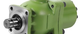
Gearbox of vertical milling machine models 6р12,6р13
The gearbox is installed in the frame housing and is connected to the electric motor using an elastic electric coupling, allowing a misalignment of 0.5-0.7 mm.
The gearbox is lubricated using a plunger pump. Pump capacity 2 l/min.
The gearbox provides the required rotation speed without sequentially passing through intermediate stages.
The handle 18 moves the rack 19, moving the main roller 29 with the switch disk 21 in the axial direction.
The racks engage in pairs with gear 32. A switch fork is attached to each pair of racks. While moving, the disk presses on the pin of one of the pair. thereby ensuring the reciprocating movement of the slats.
Main components of the machine
The machine, as mentioned above, is quite standard in terms of the entire assembly and the number of devices. Among the components and main parts are:
- bed;
- rotating head;
- table and slide;
- boxes: gears, feeds, switching;
- electrical equipment;
- console.
Experts insist that the equipment is based on the use of only high-quality and original spare parts. But, as practice shows, now they are quite difficult to find, so parts from other mechanisms are used, if, of course, they fit the overall dimensions.
Rotary head and spindle of the P-series vertical milling machine
The swivel head is a type of spare part that is mounted on the annular recess of the frame. It is secured with four bolts. The spindle is a shaft with two supports, which is located in a movable sleeve. The play is adjusted by sanding. In this case, the adjustment occurs according to the algorithm:
- remove the sleeves;
- remove the flange;
- remove half rings;
- remove the thread sample;
- remove the nuts;
- lock the nut;
- tighten the bearing;
- spindle running in;
- polishing half rings;
- securing the mechanism.
The gearbox is located in the frame housing, the misalignment is maximum 0.6 millimeters. The gearbox allows you to implement the desired one immediately without gaps.
Specifications
Main technical characteristics of the unit in question:
- 16 levels of functional table feeds;
- 1 turn of the dial moves the table along or across by 6 mm;
- vertical movement of the table per turn of the dial – 3 mm;
- the distance between the guides and the axis of the vertical spindle is 285 mm;
- table movement along – 630 mm;
- transverse movement – 200 mm;
- vertical movement – 350 mm.
In terms of accuracy, the unit corresponds to class H (normal).
Components and controls
Main components of the unit:
- electrical cabinet;
- a mechanism for lubricating the console itself and the entire working surface;
- slider;
- earring;
- milling head with a rotating mechanism;
- Desktop;
- unit with console;
- spindle drive area;
- cast bed;
- gearbox;
- equipment with electrical parts.
The main part of the spindle support is bearings. The main controls of the machine include:
- automatic switch off the power supply;
- spindle rotation switch button;
- buttons for spindle start and feed;
- handles for: switching modes of feeding the working surface, turning the spindle, its speeds, mechanical transmission;
- handwheel for manual table movement;
- hand lubricant pump drive handle;
- quill clamp;
- speed switch for the rotary spindle of the slider.
The pumping station transfers coolant from the pump to the cutter through a built-in pipeline. This allows you to reduce the heating of the tool during active work.
Electrical equipment
- cooling pump with a capacity of 2.2 liters per minute;
- pump X14–22M with a power of 0.12 kW;
- feed motor – 1.5 kW;
- motion engine – 15.5 kW.
Gearbox
The gearbox is located inside the frame body. An electric coupling is located between the box and the electric motor, which ensures reliable connection of these parts. Acceptable misalignment parameters are no more than 0.7 mm.
The gearbox is lubricated by a plunger pump, the standard capacity of which is 2 liters per minute.
An important advantage is that the sequence of steps can be abandoned to save time and the amount of effort required to process the part
Gearbox
This unit supplies the console, slide and table. The safety clutch and the dog clutch carry out the process of transmitting torque to the output shaft. The claw coupling is connected to the shaft using a bushing.
The rotation speed remains constant because the acceleration motion from the electric motor bypasses the first gear and the gearbox.
Principle of operation
A classic vertical milling machine operates according to the basic technological scheme, in which the main movement is the rotation of the tool (cutters, drills, etc.), and the auxiliary movement is the movement of the table with the installed part. Cutting modes and processing cycles are adjusted using adjusting levers and handles.
The number of spindle revolutions is regulated by switching the gearbox gear blocks to the appropriate position.
Accelerated movements are regulated by a separate drive through a friction clutch and intermediate gears. The kinematic scheme excludes the simultaneous activation of high speed and working feeds.
The workpiece is rigidly mounted on the surface of the work table, which has T-shaped grooves for special clamping bolts. The table with the workpiece moves along two coordinates: longitudinal and transverse, and the direct cutting process occurs due to the contact of the rotating tool and the workpiece. Various cutters, drills, taps and other axial tools are used as tools.
Control options
With manual control, adjustment and control of work processes is carried out from levers, handwheels and handles. The operator controls the feed rate and cutting modes visually using a measuring tool and dials.
Equipping with a digital display device (DDU) ensures control of the working parts during operation. The position parameters are displayed on the digital display. A device with a function of preliminary set of coordinate movement allows you to adjust the movement of nodes to the required values.
Characteristics of electrical equipment
- Main engine power 7.5/11 kW.
- Cooling pump power 0.12 kW.
- Mains voltage 380 V.
- Frequency 50 Hz.
- The type of current is alternating.
Machine drives
The supply of the 6R13F3 CNC machine contains servo-adjustable supply transmissions with electric motors with a high speed of switching on continuous electricity. The use of tracking stabilization movers in combination with motors of continuous or continuous supply of electricity in the machines guarantees the speed of precise movement of the table up to 4.8 m/min.
Defects of elements are also excluded in case of intermittent processing, unless there are defects during the transfer of delivery along one of the coordinates. You can also introduce centralized coverage of the main elements of machine tools. The use of electromechanical mechanisms for gripping mechanisms, guaranteeing a continuous clamping force of up to 2000 kg, is used quite often. For portable supply purposes, the characteristic that applies is prepared electrical wiring with a plug disconnect.
Design features of a cantilever milling machine
The design features of the machine, in addition to high productivity, are aimed at ensuring the safety of the operator working with the equipment. The unit has a movable guard. Security is also ensured:
- duplicating the stop buttons of the unit;
- blocking system;
- mechanism for proportional reduction of feed during exit and entry.
There are other design features that make the job more efficient.
Dimensions and weight
The machine is a large piece of equipment. Its weight is 4200 kg. Unit dimensions:
- length – 256 cm;
- width – 226 cm;
- height – 212 cm.
The table surface has dimensions of 1600x400 mm.
List of components
The main components of the unit are the same as in most milling machines. But all components have some design features that allow them to perform the necessary functions:
- Cast frame. This is a wide rectangular platform, on pins with a vertical neck.
- Spindle head with sleeve. A rotary mechanism fixed in the annular recess of the frame, with a motor for clamping the cutting part.
- Control cabinet. It includes an electric spindle drive, as well as a gearbox, control panel and several important switches.
- Front console. The engine of the table guide elements, and devices for adjusting their movement.
Design features also include:
- Mechanized tool fastening. This increases the accuracy of part processing.
- The machine table is capable of rotating around a vertical axis by 45°. This way you can mill helical spirals.
- Automatic braking of the spindle head.
- Three operating modes: manual, automatic and jog.
- Limitation of the gap in the screw pair.
The additional rigidity of the machine makes it possible to process plates made of hard and super-hard synthetic materials.
Description and location of controls
One of the main controls is the gearbox, which contains 18 spindle speeds. For this purpose there is a special head with divisions. A handle for clamping the sleeve is installed separately.
The feed drive is controlled using normal and high speed clutches. There are also mechanical slide clamps, as well as consoles on the guide parts of the frame. All working elements have separate flywheels for manual control.
Features of the structure of the rotary head
The bed serves as the base for the rotating head of the unit. The head itself is equipped with a mechanism for manual and axial movement. This allows you to process surfaces that are located at an angle of 45°.
The rotating head is centered in a ring recess, to which it is attached with 4 bolts. The spindle head itself is a two-support shaft, which is mounted in a retractable sleeve. The frame pump lubricates the bearings and gears of the rotary head.
Machine design, its features
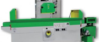
Appearance
The vertical milling machine of this series is largely similar in its characteristics to the previous model. The difference lies in the power of the power plant and the size of the desktop. Therefore, 6P13 is often used for processing medium and large workpieces made of steel and non-ferrous metals.
The main purpose of a milling machine is the formation of grooves of various shapes on the surfaces of a part using the milling method. To do this, you can use cutters of standard shape, including those with carbide tips.
The technical and design features of the equipment include the following factors:
- vertical arrangement of the quill spindle;
- possibility of moving the cross table horizontally and vertically. This unit is characterized by a large feed value;
- availability of a copy device. It is designed for processing curved surfaces of the workpiece;
- spindle head rotation mechanism. This process is carried out manually, so the machine must be stopped before changing the position of the cutting tool.
To improve the quality characteristics, the 6P13 machine model is equipped with a cooling system. Using an electric motor, coolant is supplied to the workpiece processing area, thereby reducing the temperature heating of the surface.
Another advantage of the machine is its relatively large specific gravity. This is due to the properties of the manufacturing material – cast iron. The frame and supporting vertical support are made by casting. The center of the equipment is located at the bottom of the structure. Additionally, the spinel head block has a counterweight, which has a beneficial effect on stability.
Specifications
Model 6M12P has technical characteristics:
- spindle speed 31.5–1600 rpm;
- drive power 7.5 kW;
- number of speeds 18;
- milling spindle hole 29 mm;
- table 1250×320 mm;
- spindle distance from table 30–400 mm;
- spindle cone No. 3 according to GOST 24644-81.
The machine has switching stops for all movements of the table and slide.
Bed and console
The bed has a trapezoidal shape and is rigid. Inside there is a gearbox and an electrical cabinet. The console moves vertically along rails at the front of the rack. It contains the feed box and all components associated with the longitudinal and transverse movement of the table. In the Z axis, the console lifts the table. Movement is carried out by rotation of the vertical shaft.
Controls
The handles for moving the sled and table are located on the console, in front. Switching direction is in the direction of travel. All controls are duplicated on the panel.
Electrical equipment
The machine has 3 electric motors:
- main drive 7.5 kW;
- feed drive 2.2 kW;
- cooling system pump 0.125 kW.
Push-button activation. The starting equipment is located in 2 niches on the frame. To quickly switch on all components, the machine is equipped with a pulse switching on of the electric motor. Spindle braking is dynamic. Installed: magnetic starter, selenium rectifier and intermediate relay create a smooth increase in braking torque.
Gearbox and spindle
The gearbox is located at the top of the frame. The switch is located on the side of the body. The spindle is mounted in an angular head, which rotates 45⁰. Through a conical pair, the torque from the gearbox shaft is transmitted to the spindle. The tool does not move vertically.
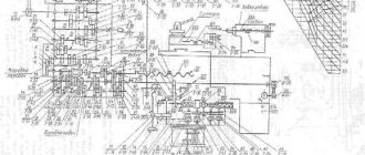
Scheme of a CNC machine 6р13ф3
The unit is characterized by a rigid base.
This is ensured by the fact that its frame has a well-developed base with numerous ribs. There are vertical guides in the front part of the bed. The console moves along them.
There is a window at the top of the frame. Through it the operator gains access to the pump and gearbox. Switches equipped on the frame limit the movement of the console.
The spindle head includes the following elements:
- sled,
- gearbox,
- slider
The slides are mounted to the frame with bolts, and their alignment occurs in its neck. The movement of the slide with the slider occurs along rectangular guides.
The console of the device serves as its basic element. Its role is reduced to combining the drives for vertical and transverse movements of the table. There is a two-stage gearbox inside the console.
Operating rules
Like all mechanisms of this weight category, 6T13 requires installation on a concrete foundation with a thickness of at least 30 cm. The surface must be perfectly flat to reduce the risk of inaccuracies during fine milling. The initial start-up involves filling the lubrication system reservoir with oil and idling in all modes. It is recommended to make the first oil change after a week of operation, the second after a month, and then once every 3 months. Preventative flushing of the oil reservoir is carried out once a year.
Before each start of the machine, the operator uses the tool release-clamp lever in the spindle. Changing the position of the workpieces, switching speeds and modes while the head is rotating is prohibited. The control cabinet doors providing access to the electric drives are locked with a key. If there is any malfunction, operation stops and the systems must be inspected by an electrician.