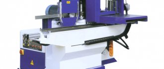
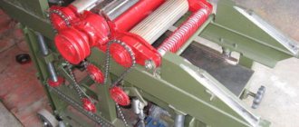
Various designs of jointing machines
Structurally, jointing equipment manufactured in industrial conditions is very different from machines made independently. They differ in the materials used, technologies, auxiliary equipment, etc. But this does not mean that a homemade jointing machine made from a simple electric planer will not be in demand for home use. It is quite suitable for processing small parts in small quantities.
There are two main types of wood planing machines:
- Single-sided machines (the production of this option will be discussed). With such equipment, only one surface can be processed in one pass. Structurally, these are the simplest devices;
- Double-sided or two-spindle. Such a device can simultaneously process two adjacent surfaces of a part. It is quite difficult to make such equipment yourself.
In addition to the above types, you can also add that machines can be both stationary and mobile.
Drawings and diagrams
Before assembling the benchtop jointer, it is necessary to develop drawings. In the process of creating them, you should take into account the elements that will be part of the diagram. Standard jointers without additional features include:
- bed;
- shaft equipped with blades;
- rotating roller;
- engine;
- three tabletops;
- emphasis
In the process of developing drawings, the master must indicate the main distances between the key elements of the stationary structure. To do this, you will need to take into account the location of the motor, roller and shaft with blades. The circuit will allow you to determine how much the number of output rotor rotations will decrease if there is an increase in power, and vice versa.
main idea
Yes, such a homemade jointing machine, unlike serious industrial designs, has a number of disadvantages, namely:
- Cannot boast of high processing accuracy;
- The width of the workpiece is very small - only 110 mm;
- Lightweight is a disadvantage, since a heavy massive base always gives the device stability and, as a result, ease of use, which ultimately improves the quality of the result.
- Low power, limited by the power of a household electric planer;
- The body material is wood, that is, not durable;
However, it also has undeniable advantages that make it very useful for achieving certain goals and performing a number of tasks, since it has the following advantages:
- Low cost - serious jointing machines cost tens and hundreds of thousands of rubles, and the cost of this homemade jointing machine consists of the cost of the plane and materials;
- Compact and portable - it can easily be stored anywhere in the workshop and can be deployed for work in a matter of minutes.
- The simplicity of the design affects its reliability and maintainability.
- The ability to make the necessary dimensions of the machine “to suit you”, for example, you can increase the length of the work table or change the height.
Selection of components for the jointer
Guards for the knife shaft of a jointing machine.
In order to assemble a jointer from an electric planer, it is not at all necessary to disassemble a new tool. A plane that was previously used for its intended purpose is quite suitable. The disadvantage of some modern models of such devices is that their plastic casing becomes loose over time and cracks and chips appear on it. It becomes unsafe to work with such a plane, but it fully meets the requirements for creating a jointing machine. All you need to do is turn the plane over and secure it in this form in a pre-prepared workbench.
Choosing an electric planer model is one of the important points when assembling the machine. Most models have a planing width of 82 mm, which is quite suitable for home use. More expensive and powerful planes are equipped with a 100 or 110 mm shaft. In the latter case, such parameters make it possible to run boards and beams 10 cm wide through the tool, without leaving untreated areas.
It is worth paying attention to the additional functions of the electric planer: some models are already equipped from the factory with special devices that allow you to turn the tool into a full-fledged jointing machine. This type of planer can be fixed with the sole up, and safety of operation is ensured by a spring-loaded protective cover.
If there is a need to process materials whose width exceeds 110 mm, then doing this with an electric planer will be very inconvenient, since the board will have to be run several times, which increases time and reduces the accuracy of the work. In this case, it is worth considering the possibility of assembling a powerful jointer, the main components of which will be a separate shaft and a powerful electric motor. Although the cost of the shaft is often more than half the price of all materials, having such a tool in your arsenal, you will no longer be limited in your woodworking capabilities.
Diagram of the conveyor mechanism of a jointing machine.
The planing width of a full-fledged jointer equipped with a shaft ranges from 25 to 85 cm or more, but one must take into account the fact that an increase in this parameter entails an increase in engine energy consumption.
Optimal engine power depends on several parameters:
- shaft width;
- number of knives;
- width of processed lumber.
The relationship is direct: the greater the importance of the listed parameters, the higher the engine power should be. For home machines, 1.5-2 kW motors have proven themselves well. The shaft rotation speed of such machines is 4-4.5 thousand revolutions per minute, the width of the processed material is 25-40 cm.
Preparing the necessary accessories for work
To make a jointing machine with your own hands, you will need materials, equipment and tools, namely:
- Manual electric planer. Will be used as a woodworking tool. It is best to use high-quality, branded Makita or Bosh power tools - this is an additional guarantee of productive, long-term work;
- Jigsaw with files. Alternatively, you can use a regular hand jigsaw, since we will only need it once to make one part;
- Drilling machine with drills or drill;
- Circular saw or any other sawing machine. Alternatively, you can use a simple handsaw;
- Electric screwdriver;
- Wood screws (3.5x40 or 3.5x45);
- Plywood 10-15mm, for tables and other small parts, 18-20mm - for the side wall of the bed. Alternatively, you can use chipboard or OSB, but this is an extremely undesirable option;
- Solid wood for making a side support, approximately 15-20mm thick.
This is an indicative set of what you might need to make a homemade jointing machine.
Description of the tool
Thicknessers are machines for wood processing that allow planing and leveling the surface of lumber to produce boards of a given thickness. This type of wood processing is carried out by using lumber in construction and making various structures from them. Planing equipment is in demand on the market and is popular with ordinary homeowners who independently engage in construction at the dacha and in their own home.
Self-made surface planers are distinguished by their simplicity of design, which allows them to be made using an electric planer, grinder and other similar power tools as a basis. You just need to make sure that you have the appropriate diagram, which you should adhere to when making homemade equipment.
Machine parts
Let's look at the main structural elements:
| Name | Description and purpose |
| Machine base | The bottom part of the machine where everything is mounted. |
| Side wall | The supporting structure of the machine, which serves to mount the electric planer and both tables. |
| Rear table (fixed) | Together with the front table it forms the plane of movement of the workpiece. Attached to the side wall. |
| Front table (adjustable height) | Together with the back table it forms the plane of movement of the workpiece. Attached to the side wall. |
| Side stop | Fixed on the back table. Used to give direction to the movement of the workpiece. |
| Spacer corners (stiffening ribs) | They serve for general strengthening of the structure, as well as to support a given 90-degree angle. |
| Electric planer | The main element of workpiece processing. |
Additional Assembly Tips
The metal for the stove is cut with a grinder or jigsaw. To cut a groove, it is convenient to use an electric jigsaw, having previously drilled a hole for its file in the slab, or an electric drill with an appropriate attachment. The edges of the slot are processed with a file so as not to get injured by them later.
You can secure the metal base plate with flat head screws (so that they do not interfere with work) or by welding it. The first option is preferable because, if necessary, the electric plane is easy to disassemble.
Before installing the drum, it is recommended to check the sharpness of its knives. If it is bad, then it is better to sharpen the blades immediately, using, for example, a regular whetstone. It is necessary to constantly ensure that the cutting attachments are well secured without distortion.
The basis for making your own knives are steel plates or hacksaw blades for metal, sharpened at an angle of 30 degrees.
Hacksaw blade
The sequence of making an electric plane from a grinder with the working drum placed in a vertical position is demonstrated in the videos below. It also shows possible errors when assembling a homemade product.
Another option for creating a homemade electric planer from an old, non-working model is shown step by step in the video below.
Using the made power tool, you can process boards, beams and other workpieces. An electric planer assembled with your own hands must be used in compliance with safety requirements. The parts must be fed correctly to avoid getting your fingers caught in the drum.
There are many options for homemade electric planes. They have varying degrees of complexity, as well as different functionality. In this regard, the limitations are mainly related to the technical thinking of the inventors and the parts and materials available “at hand”. If necessary, the manufactured equipment can also be equipped with automation equipment.
Making a homemade jointing machine
Side wall
First of all, we will make a side wall, for this we use plywood 18-20mm thick with dimensions 150x480mm. By cutting out a place in the workpiece in which the electric planer will be fixed. This should be done using an electric or manual jigsaw, since the sample shape has a complex configuration.
Using a drilling machine, two grooves should be made in the side panel at a distance of 70 mm, with their help, in the future, the base of the front table will be attached.
Machine base
We make the base. This is a simple rectangle that needs to be cut on a circular saw or other sawing machine from the same plywood 18-20mm thick with dimensions 180x480mm. Everything is simple here - we connect the base and side wall at an angle of 90 degrees with self-tapping screws into the end of the wall.
In the future, the plane will be installed as follows.
Back table
The back table is also made of 18-20mm plywood with dimensions of 150x600mm; a technological opening is cut out to get this shape.
The end edge of the opening must be cut at an angle. This can be done on a circular saw or jigsaw.
Next, unscrewing 4 screws, remove the fixed “sole” from the electric planer and mark the table of the future machine.
Having drilled the necessary technological holes, they need to be countersunk a little so that the standard screws are recessed “flush” and do not interfere with the movement of the workpiece.
We install our homemade back table in place of the removed sole of the electric planer using standard screws. After this, you need to fix this table on the side wall with self-tapping screws into the end of this wall.
Front movable table
The front table, which must be adjustable in height, is made of two rectangular pieces fastened at an angle of 90 degrees. For greater structural strength, you need to make triangular stops between them. In this example, everything is attached with self-tapping screws; however, for greater strength, it is recommended to coat the joints with wood glue. The end result should be a design like this.
At a distance of 70 mm from each other, you need to make two through holes with a diameter of 8-10 mm and hammer furniture drive nuts into them. It is better to do this before assembling the base.
Installation of the movable table is done using two screws on the back of the side wall. For convenience, you can use bandages with a winged head or make homemade holder mounts. The installation should be carried out so that the plane of the moving part of the “sole” of the electric planer is in the same plane as the movable table of the jointer.
Side stop
The side stop is needed to ensure smooth and parallel movement of the workpiece, as well as to establish an exact 90-degree angle between the work table and the stop plane. The stop is made simply - from two parts, which can be made from either plywood or solid wood. In this case, an array is used.
Two rectangular blanks are fastened at an angle of 90 degrees, forming a “corner”. After which it is rigidly attached to the stationary part of the table.
A do-it-yourself jointing machine made from an electric planer is ready for use.
How to make a surface planer from an electric planer with your own hands?
To make a surface planer from an electric planer with your own hands, you will need a small set of metalworking and electrical processing tools, as well as a certain amount of lumber.
In general, a professional thicknesser is a special carpentry tool for mechanical processing of wood, in particular used for drawing marking design lines.
The product is also used to level the plane of specific lumber. A homemade surface planer has an electric planer as the main cutting mechanism.
► Tools and materials for making
Materials for the product:
- Plywood 15 mm thick;
- Planks and bars made of wood – 15x15, 25x25;
- Drive gears – 4 pieces;
- Bicycle chain – 1 pc.;
- Set of nuts with M14 thread;
- Set of washers;
- Screws for 25 – 100 pcs.;
- Threaded screws – 4 pcs.;
- Stands for screws – 4 pcs.
Also, to make a surface planer at home, you need a set of certain tools, in particular an electric planer and a jigsaw.
Tools:
- Electric jigsaw;
- Construction electric planer;
- Set of keys and screwdrivers;
- Screwdriver;
- Ruler and corner.
A construction electric planer will be used as the main mechanism for the product.
1. Plywood base
The base for the surface planer is made of plywood sheet with a thickness of at least 15 mm. The material is cut to the design size. The shape is a rectangle with an approximate size of 400x500 mm.
2. Fastening stands for a platform with an electric planer
The stands are also made of 15 mm thick plywood. In this case, the element is cut out from several parts and assembled on site. The unit is fastened with screws from the reverse side to the main base, to which an electric planer with a working platform will also be installed.
3. Making a platform for an electric planer
The construction electric planer is mounted on a special platform, which has a dimensional slot in the center. The technical hole must be cut with a jigsaw strictly according to the shape of the plane. The electrical appliance itself is installed using clamping strips and screws.
4. Installation of threaded screws with gears on the platform
A drive mechanism is mounted on the platform under the thicknesser, which will ensure the raising and lowering of the platform. Threaded screws are installed at the 4 corners of the base, where the electric planer is already mounted on screws.
5. Installing the platform on stands
The upper part of the surface planer with a platform and an installed plane is mounted on the main plywood stands, and fastening is carried out using screws. The electric planer cable is laid everywhere so that its braiding is not damaged during system operation.
6. Handle for controlling the platform with an electric planer
The handle on the thicknesser is mounted on one of the threaded screws. Fastening is carried out using a set of washers and nuts. To securely screw the fastening nut, you need to make a through hole on one screw.
It is important to ensure that the electric planer does not fall off its mounts.
7. Measuring bar and pointer
A measuring bar must be installed without fail to measure the material during its processing. As a bar, you can use part of a regular plastic ruler, which needs to be cut to 6-8 cm. The pointer for the thicknesser is used in the form of a regular arrow.
The finished thicknesser assembly is tested on rough material in order to further configure it. A working electric planer must be regularly maintained, in particular, it is necessary to periodically sharpen the blade and carry out cleaning.
Video: assembling a surface planer using an electric planer with your own hands.
Safety when working with homemade equipment
When working with any tool, you must follow safety precautions, as ignoring them can cause various injuries. We will briefly list the recommended measures to ensure the safety of the master’s work on this machine.
- It is recommended to remove sharp chamfers and sand all manufactured parts to eliminate the possibility of hand injury (splinters, etc.)
- When working, it is necessary to use a chip extractor or a special vacuum cleaner, for example, a cyclone type, to remove sawdust and dust from the sawing area, which can cause the following harm:
| To the Master | Respiratory and eye contact |
| Tool | Getting inside the instrument and:
|
| Process | Chips and sawdust getting between the workpiece and the table, resulting in poor fit and misalignment - the result is uneven processing. |
- When working, it is necessary to use pushers, since when working with small parts, it is possible that the master’s hands will get into the cutting zone, which will lead to injury.
Additional Assembly Tips
The metal for the stove is cut with a grinder or jigsaw. To cut a groove, it is convenient to use an electric jigsaw, having previously drilled a hole for its file in the slab, or an electric drill with an appropriate attachment. The edges of the slot are processed with a file so as not to get injured by them later.
You can secure the metal base plate with flat head screws (so that they do not interfere with work) or by welding it. The first option is preferable because, if necessary, the electric plane is easy to disassemble.
Before installing the drum, it is recommended to check the sharpness of its knives. If it is bad, then it is better to sharpen the blades immediately, using, for example, a regular whetstone. It is necessary to constantly ensure that the cutting attachments are well secured without distortion.
The basis for making your own knives are steel plates or hacksaw blades for metal, sharpened at an angle of 30 degrees.
The sequence of making an electric plane from a grinder with the working drum placed in a vertical position is demonstrated in the videos below. It also shows possible errors when assembling a homemade product.
https://youtube.com/watch?v=SY6xchF8VzU
Another option for creating a homemade electric planer from an old, non-working model is shown step by step in the video below.
Using the made power tool, you can process boards, beams and other workpieces. An electric planer assembled with your own hands must be used in compliance with safety requirements. The parts must be fed correctly to avoid getting your fingers caught in the drum.
There are many options for homemade electric planes. They have varying degrees of complexity, as well as different functionality. In this regard, the limitations are mainly related to the technical thinking of the inventors and the parts and materials available “at hand”. If necessary, the manufactured equipment can also be equipped with automation equipment.
Purpose
The machine combines the capabilities of a circular saw and a jointer. The circular saw is used for sawing large volumes of timber, boards, laminate, plywood, drywall, and soft alloy products. Sawing is carried out quickly, accurately and precisely to size, which cannot be achieved using hand tools.
The jointer is designed to remove the top, rough layer of material and make the workpiece smooth. Only wood is processed on jointing machines. There are double-sided models that simultaneously process two planes. The operations performed on circular and jointing machines are carried out one after another, so it is logical to combine them into a single device.
Planer device
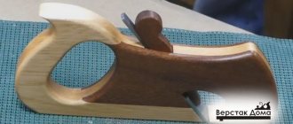
During the evolution of the plane, quite a lot of its varieties have appeared, which can not only process the planes of wood, but also be used for figured cutting. To enjoy manual labor, you need to be able to choose the right plane, and then you will get real works of art from an ordinary piece of wood.
Modern planes can be divided into wooden and metal models. Each of them has its own advantages and disadvantages, but in terms of design, the instruments are similar, like twin brothers.
A standard plane consists of the following parts:
- sole, also known as body;
- cutter;
- wedge;
- slot for chip exit;
- cutter clamp;
- cutting depth regulator;
- horn - front handle;
- emphasis - rear handle.
The key element of the design is the cutter - this is a cutting tool made in the form of a pointed plate.
The blade is positioned at a given angle to the surface being processed. Thanks to the regulator, the knife extends to a certain distance, which allows you to finely adjust the depth of cut and the thickness of chip removal. In factory models, the blade sharpening angle is standard, but professional carpenters change it depending on the type of wood being processed.
The handles also play a certain role. The front one, called the horn, performs a guiding function and usually has a curved shape that provides a better grip on the hand. The rear one is a stop, thanks to which the force necessary for work is created.
With the sole, which can be wooden or metal, everything is not so simple. The main criterion for this structural element is a perfectly flat surface.
If this requirement is not met, it will be difficult to use a hand plane, and you can simply forget about planing accuracy. Taking these nuances into account, a metal sole looks preferable: it is made according to a template, so a priori it has the correct geometry. However, mistakes made by the manufacturer during casting reduce these advantages to zero. Moreover, the metal is susceptible to corrosive changes.
A wooden sole is lighter, and if deformed, you can straighten it yourself, breathing a second life into the plane. However, wood is not a durable material; it is subject to mechanical wear and loses its original properties when exposed to moisture or high temperatures for a long time.
Despite the standard design, there are more than 10 types of planes, and each tool performs a specific function when processing parts. Let's take a closer look at these products.
Circular saw shaft
Shaft for a circular saw and bearing assembly
Let's look at the picture, which shows a sectional view of the shaft assembly
• shaft (1) • bearing housing (2) • bearings (3) • internal saw blade clamping sleeve (4) • external saw blade clamping sleeve (5) • clamping nut (6) • driven shaft pulley (7) • clamping nut, lock washer, key (8)
Sharpened from steel 45. The manufacture of the shaft can only be entrusted to highly qualified specialists, where a prerequisite is strict compliance with the technical requirements for the seating surfaces of shafts and housings in accordance with GOST 3325-85. On the saw blade mounting side, the following are mounted on the same diameter: a bearing; clamping inner sleeve; saw blade; clamping outer sleeve, so take this into account when you add tolerances and fits to the working drawings.
BEARING CASE
It is sharpened from steel 20. M6 threads are cut into the four mounting holes. Before pressing the bearings, fill the housing with Li-tol-24 lubricant.
1204 ball radial double-row spherical GOST 28428-90. They have two rows of balls. The inner surface has a curved shape. Covers can be provided in the bearing housing to protect them from dust and wood chips. But this solution, in general, will significantly complicate the design and increase its overall dimensions, therefore, we will not use it.
INNER CLAMPING BUSH
Made from steel 45
EXTERNAL CLAMPING BUSH
Made from steel 45
M16 round spline nut GOST 11871-88, clamps the saw blade.
DRIVEN SHAFT PULLEY
We will make it from aluminum alloy according to the general technical specifications GOST 20889-88.
The M16 round spline nut in accordance with GOST 11871-88 clamps the driven pulley.
Multi-claw (version 2) GOST 11872-89, serves to fix the nut relative to the shaft and does not allow it to unscrew during rotation.
Keyed connection with parallel keys, tolerances and fits GOST 23360-78. We select the length of the key from the size range - 22 (mm)
Well, and most importantly, in order for the assembled unit (shaft for a circular saw) to work without the slightest runout, it needs to be balanced in the factory using special equipment.
In the next article we will look at the construction of a circular saw bed.
