Typically, the following devices and consumables are used for this type of equipment:
- — clamps of various types, for body work;
- — mounts for point-type tools;
- — special devices for straightening dents;
- — an electrode for a spotter, there can be many varieties depending on the type of application;
- — special devices and equipment that allow drawing out the ribs;
- — impact nozzles, like a reverse hammer;
- — washers for spotters of different shapes, round and oval;
- - special attachments made of hairpins, shaped like a crescent.
We invite you to watch a video about using various accessories for the spotter.
Types of electrodes for spotters
The electrode for the spotter can be of the following type:
- - for welding nails;
- - for welding studs;
- — magnetic type, for welding rivets;
- — for welding washers;
- - for heating deformed metal;
- — flat type for hot heading;
- — for welding an oval washer;
- — for welding a three-beam star;
- - coal type, for heating the metal.
You can purchase all types of the listed electrodes for a spotter in our company; we have a large assortment of accessories and consumables for body repair.
Types of fasteners
In our warehouse you can purchase the following types of fasteners:
- — Insulation nails, used to fasten insulation. The nail is welded to the body, and then the insulation is pinned onto it. The sharp part of the nail is covered with a special cap.
- — Washers for spotters are one of the most popular types of fasteners. We have such oval-shaped washers in stock, with an additional tip. It is this tip that is welded to the damaged area of the metal. There are two modifications of such washers, with a straight and curved tip. To correct dents, a special reverse hammer attachment is connected to the spotter washers, which can also be purchased from us.
- — The three-beam star is itself an electrode that is welded to the damaged part of the body for subsequent repairs.
Calculation and manufacture of a welding transformer
The principle of calculating the unit is specific, since often the standard method and diagram are not suitable. During the manufacturing process, the dimensions of the components must be adjusted to the materials that are available - often to the magnetic circuit.
The core differs according to the type of winding:
- Disk. The distance between the primary and secondary windings can be remote. A significant amount of the magnetic flux of the primary winding is free from the secondary. Characterized by strong electromagnetic radiation.
- Cylindrical. One winding is wound on top of the other. The magnetic flux of the turns of the primary winding adheres to the secondary one, since there is a small distance between them. This unit has a rigid characteristic.
Also, the transformer core is divided by shape into the following types: armored, rod, toroidal.
Armored
It has an W-shape, with windings on the central rod. The armor type is more difficult to use. If equipment identical to industrial versions is manufactured, the circuit can be calculated using standard methods.
Rod
Its shape resembles the letter P. It has higher efficiency. A high current density in the windings is possible. Therefore, the unit is often made of rod teak.
Toroidal
Has the best characteristics. It has the shape of a ring with a rectangular cross-section. The core is equipped with two or more windings that are wound directly onto it. It has a small size and light weight. It is easy to install and connect.
Exhaust devices
As we wrote earlier, the spotter welds a fastening element to the damaged area of the body, and then either a reverse hammer or a pulling device is attached to this element.
A traction device is used for smooth, shock-free pulling of the damaged area. Typically, such devices consist of a durable frame that is mounted on four legs. This design provides good support. The frame is durable and can withstand pulling force with a large margin. The hook of the exhaust device engages with the welded fasteners, and smooth extraction is performed.
We have two types of such devices in stock. One type uses one hook to engage the fastener, while another device can use six hooks at once (this is convenient if the area of the damaged area is large and several fasteners are welded onto it at once.
More detailed information can be obtained from our experienced specialists. They will be happy to advise you on all types of consumables for the spotter.
Spotter is the common name for a single-sided spot welding machine designed for repairing car body parts. Its design is quite simple, so any home craftsman with experience working with electrical devices can make a spotter with his own hands. The only thing that cannot be mistaken is the choice of power, calculation of the current strength and the number of windings. Craftsmen use various devices as power sources, but not all of them are capable of providing optimal operating conditions.
For example, a homemade microwave spotter, even when using several transformers from this household appliance, is generally suitable for warming up. If there is no sufficiently powerful electrical network at the repair site, devices with an autonomous source are used, consisting of a battery and a voltage interruption circuit. Such devices have one significant drawback - limited operating time. When assembling a homemade spotter, you can use various control systems: from a simple button with a relay to an inverter source. In the latter case, the current supplied from the inverter to the welding site is regulated with high accuracy both in duration and in pulse amplitude.
DIY spotter washers
The spotter belongs to the category of equipment for performing contact welding. During operation, the unit produces a current discharge, which melts the metal in a split second and allows spot welding without the usual pliers.
For correct operation, a replaceable attachment is used - a reverse hammer, which simultaneously with the spotter straightens out dents, thereby imparting lost rigidity to the metal and returning its original shape.
If you want to use the unit for small amounts of work, then it is easier to assemble the device from improvised means. In this review from the editors of Seti.
guru we will answer the question of how to make a spotter with your own hands, we will consider the sequence of assembling such a unit from various household appliances and unnecessary equipment.
Industrial spot welding device
A do-it-yourself spotter is most often used for straightening a car and leveling out dents on metal.
This type of equipment is very popular among workshop technicians, since during the process of straightening the body there is no need to dismantle the fender or door of the car. All work can be carried out directly on the outer part of the casing.
It is especially convenient to work with the device in those places that are difficult to get to.
During operation, the device produces a discharge, the metal heats up, and welding occurs at the point of contact.
Welding with a spotter does not leave deep marks and, after leveling, can be easily removed with a grinder.
The fact is that heating and cooling at the point of contact occur so quickly that the metal does not have time to oxidize and react.
Moreover, homemade models can be adjusted in such a way that the current strength and exposure time can be changed depending on the thickness of the metal that needs to be processed.
The spotter consists of the following elements: 1 – reverse hammer, 2 – housing where the power supply and control unit are located, 3 – hook, 4 – electrodes, 5 – gun.
Two cables come from the body of the device: ground and a working wire with a gun. The gun is what the welder operates in his hands.
At the same time, or before this stage, the master knocks out small “mounds” with a reverse hammer, onto which a discharge is applied by a spotter.
They are subsequently cleaned, thereby thickening the metal and obtaining the necessary shape and strength.
For your information! The action of the spotter is based on such a physical phenomenon as current resistance. In this case, the use of conventional welding materials (consumable electrodes, welding wires and others) is not required.
Is it possible to make a spotter with factory specifications?
If you correctly calculate the parameters, select the appropriate components and make high-quality not only the power supply, but also the tool accessories, then a homemade spotter in its functionality will be no different from its factory counterpart. If you have some amateur radio skills, it is easy to make the power supply and the necessary wires yourself. As a welding gun, you can use any product of a suitable shape, the design of which would allow you to strengthen the threaded contacts at its ends and would be convenient to use.
The gun and reverse hammer will require several parts, which are best turned on a lathe. Some electrode tips can be made with your own hands using ordinary plumbing tools, but some are still better to order or purchase ready-made. In order to operate a home-made device, additional devices may be required (pullers, combs, rods), which can also be made independently. Consumables for a spotter (welding washers, studs, corrugated wire, carbon electrodes, etc.) are inexpensive and are freely sold in specialized stores.
Brief description of the operation of spot welding spotter
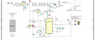
The schematic diagram of the control unit is shown in the figure (Fig. 2). When the supply voltage is supplied, the data stored in non-volatile memory for the first button is loaded. The indicator displays the information provided by the controller. In parallel with the output of information, the state of the buttons is monitored; when a triggered button is detected, the corresponding subroutine is launched. The information on the board is updated in connection with the new request.
Each time the button contacts are activated, a sound signal is heard; its absence means that the controller is malfunctioning or frozen.
Photo 3. Spotter indicator panel.
Using the buttons, you can select the desired operating mode and set the desired pulse parameters. The selected mode can be saved in memory for later use.
In the "Operation" mode, the controller operates as follows:
- The indicators turn off, the controller monitors the voltage level at the AIN1 contact.
- When the voltage drops to zero, the counter starts with a set pause period.
- At the end of the countdown, a command is issued to the thyristor (triac) control chip. The process is repeated at each cycle of the mains voltage to use only the positive half of the cycle. This improvement avoids the magnetic saturation mode of iron.
Mains voltage control occurs along the chain from the power supply, through the X-1 connector contact to the SIN controller contact. Elements VR2 and Q2 correct the signal shape. The voltage to open the triac is supplied to connector X3, pins 1 and 2.
Main components for assembly
To assemble and test a homemade spotter, you need the following components and consumables:
- Frame. Sheet metal box structure with front and back panels. Ventilation holes and a ground terminal are required.
- Power supply. In its simplest form, it is a do-it-yourself transformer with a circuit breaker in the primary circuit.
- Power cables. The welding cable must have a terminal for connection to power and a threaded contact for connection to the gun, and the ground cable must have a terminal and contact pad for welding connection to the body part.
- Control circuit. The minimum version includes a switch button on the gun, an input voltage cut-off relay, control wires and a control circuit power supply.
- Welding gun. At one end there is a contact threaded connection for connecting electrodes and adapters, and at the other there is a socket for connecting a welding cable.
- Equipment. The basic version includes electrodes for washers and pins, a return hammer and an adapter for connecting a carbon electrode.
Provided that all components are made without deviations and nothing has to be adjusted or altered, for DIY assembly you will need ordinary plumbing and power tools. Measuring instruments you may need are a tape measure, a caliper and a multimeter.
Assembling a reverse hammer (inopuller) with your own hands
In order to assemble a reverse hammer with your own hands, you need the following parts:
- steel rod 60 cm long, 17 mm in diameter, with threads on both ends;
- steel bushing with a through hole with a diameter of 15 mm, a length of 15 cm and a diameter of 40 mm;
- return spring;
- travel stop nuts and washers;
- adapters for attaching electrodes.
First, a washer is put on the end of the rod intended for fastening into the gun and the nut is tightened tightly. The rod is then passed through the bushing and return spring. The final step is to attach a washer and nut to the bottom threads, and then screw on the electrode adapter. During operation, the massive bushing will be repelled by the spring and perform reciprocating movements between the two washers.
Making a working pistol
Branded spotter pistols are usually produced in the form of devices with a pistol grip. Much of what folk craftsmen make with their own hands can only conditionally be called a “pistol.” Often it is just a cylinder with a button and a terminal for connecting a cable at the end. This is because the spotter gun consists of only three parts: the body, the contact rod and the switch. The contact rod is usually made of brass. At one end there is a thread for attaching a reverse hammer, and at the other there is a clamp for connecting power. For those who make such devices with their own hands, whether to place it in a pistol case or use it as is is a matter of personal preference. At the same time, despite the low welding voltage, it must be insulated: these are the requirements of safety regulations.
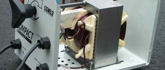
Transformer for spotter
Any transformer is suitable for making a power source for a spotter. Videos of the manufacture of spot welding machines based on transformers for microwaves and other household appliances are distributed on the Internet. At the same time, the authors of these crafts do not report what current their devices are designed for, and this is very important, since the penetration of the metal surface during the operation of the spotter should occur in a fraction of seconds, without appearing in any way on the back side of the part. Factory devices have a power of 3÷5 kW with an open circuit voltage of 7÷8 V (welding voltage - 1.5÷2 V).
For a spotter assembled by yourself and intended only for body repairs, a power of 1.5÷2 kW is sufficient. It is not difficult to calculate how many turns there should be in the secondary winding of a transformer. To do this, the number of turns of the primary winding (new) must be divided by the quotient of 220 divided by 7 ÷ 8. Usually it turns out just a few turns.
If the number of turns in the network winding is unknown, then the secondary voltage can be selected experimentally by unwinding or adding turns. It should be noted that for the ground and the gun, cables with the same cross-section should be used, corresponding to the maximum current of the secondary winding.
Control unit diagram
There are quite a lot of electronic circuits on the Internet that are labeled as spotter control units. Some of them refer to industrial designs of spot welding installations (including old ones), others are replete with electronic components and have redundant parameters, and a number of circuits are not at all related to our topic. Many of the proposed devices implement adjustments to the open circuit current and voltage, as well as control of the duration of the welding pulse. Their manufacture requires a certain skill, and the parts used are not that cheap. Choosing one of these schemes is advisable if you plan to make a spotter for commercial use in a small auto repair shop. And for devices that are made by hand and used at home, there are simpler solutions.
Do-it-yourself washers for a spotter - Metalist's Guide
The spotter belongs to the category of equipment for performing contact welding. During operation, the unit produces a current discharge, which melts the metal in a split second and allows spot welding without the usual pliers.
For correct operation, a replaceable attachment is used - a reverse hammer, which simultaneously with the spotter straightens out dents, thereby imparting lost rigidity to the metal and returning its original shape.
If you want to use the unit for small amounts of work, then it is easier to assemble the device from improvised means. In this review from the editors of Seti.
guru we will answer the question of how to make a spotter with your own hands, we will consider the sequence of assembling such a unit from various household appliances and unnecessary equipment.
Industrial spot welding device
A do-it-yourself spotter is most often used for straightening a car and leveling out dents on metal.
This type of equipment is very popular among workshop technicians, since during the process of straightening the body there is no need to dismantle the fender or door of the car. All work can be carried out directly on the outer part of the casing.
It is especially convenient to work with the device in those places that are difficult to get to.
During operation, the device produces a discharge, the metal heats up, and welding occurs at the point of contact.
Welding with a spotter does not leave deep marks and, after leveling, can be easily removed with a grinder.
The fact is that heating and cooling at the point of contact occur so quickly that the metal does not have time to oxidize and react. Moreover, homemade models can be adjusted in such a way that the current strength and exposure time can be changed depending on the thickness of the metal that needs to be processed.
The spotter consists of the following elements: 1 – reverse hammer, 2 – housing where the power supply and control unit are located, 3 – hook, 4 – electrodes, 5 – gun.
Two cables come from the body of the device: ground and a working wire with a gun. The gun is what the welder operates in his hands.
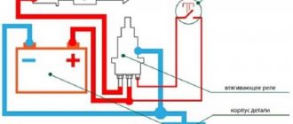
The operating technology is as follows: The mass is fixed to the body of the car from which the battery has previously been removed. The gun starts the current flow. When the trigger is pulled, a discharge occurs that melts the metal.
At the same time, or before this stage, the master knocks out small “mounds” with a reverse hammer, onto which a discharge is applied by a spotter.
They are subsequently cleaned, thereby thickening the metal and obtaining the necessary shape and strength.
For your information! The action of the spotter is based on such a physical phenomenon as current resistance. In this case, the use of conventional welding materials (consumable electrodes, welding wires and others) is not required.
Working diagram of the spotter
To correctly assemble the tool, you need to understand the basic operating diagram of the spotter.
Power supply diagram.
This scheme works according to the following principle: when the spotter is turned on, voltage is supplied to transformer T1. Next, it is converted and supplied from its secondary winding to the diode bridge.
Then it passes through the closed contacts of the “Impulse” switch to capacitor C1, which begins to charge. Since the thyristor is closed at this time, no electric current is supplied to the welding transformer.
Schematic diagram of the spotter operation
To start this transformer and receive welding current on its secondary winding, it is necessary to change the position of the “Impulse” switch, which will disconnect capacitor C1 from charging and connect it to the thyristor control circuit. The current generated as a result of the discharge of the capacitor first passes through the resistance (R1), which is responsible for the operating modes of the device, and enters the control electrode of the thyristor, which leads to its opening.
DIY spotter for body repair
The tip of the spotter is similar to a pistol; in manual mode, you can use it to adjust the time required to straighten the part; to do this, simply press the button and do not release it.
There are several options for making a spotter for body repair with your own hands from used devices. Let's look at each assembly option in detail.
We select components
and the most difficult part of the job is choosing the right transformer. To create the necessary current pulse, you need a 1500 A transformer. If you don’t have one at hand, a little later we’ll tell you how to make it yourself.
In addition to this most important part, to assemble the spotter you will need: a reverse hammer, a control unit (it contains a 200 V thyristor), a diode bridge, a contractor (220 V), and a 30 A relay.
How to properly convert a transformer for a spotter
Rewinding the transformer is the most labor-intensive step. Typically, copper or aluminum wire is chosen for these purposes. Let's look at the order of work in more detail.
| Illustration | Description of action |
| For work we use 2 empty coil blanks, our task is to combine them into one | |
| We cut off the protruding side parts from two coils, glue them with second glue, wrap them with cloth and fill them with varnish. We glue the corners with cardboard. This is done so that the wire does not bend when winding. We got one big blank. | |
| We begin winding the wire in several layers, diameter 1.1 mm. In our case, we got about 112 turns per row. We lay each layer with insulating paper. This will minimize the risks of interturn short circuits. | |
| Let's make a branch. There will be three of them. You can change the voltage on the secondary without winding it. This will slightly increase the load on the primary, but for short-term work, for example, switching the current from 3 Volts to 5 Volts, it is quite suitable. | |
| We take the wires out of the coil |
Important! The length of the outgoing ends of the secondary winding of the transformer must provide for the possibility of its connection to the output terminals, and the primary - for connection to the electrical circuit of the device. It is advisable to impregnate the transformer you have made with shellac.
If you want more knowledge on how to properly wind a spotter transformer, watch this video
Manufacturing of the control unit
The task when assembling the control unit is to correctly connect the jumpers to break the contacts of the primary network. We provided the basic diagrams earlier. In addition, the control unit contains wires, contacts for the start button, as well as other switches necessary for operation.
Selecting a spotter body and power cable
Even though you are making a homemade instrument, you need to take care of aesthetics. Therefore, it is important to make the body of the unit (what those who turn to you for help will pay attention to) functional and convenient. Think in advance about which control elements you want to place and where.
An example of the location of controls on the body of a homemade spotter: 1 – button to turn the device on and off, 2 – current regulator, 3 – pulse regulator, 4 – lever for switching from manual to automatic mode, 5 and 6 – welding cables.
The body for the spotter can be made of different materials: metal, plastic and even wood. Some craftsmen use a PC system unit. This is quite convenient, since it already has the ability to install microcircuits and coolers. Sometimes a wooden box with a hinged lid is used as protection.
Some models have a retractable telescopic carrying handle.
The task is to ensure the possibility of opening the box and access to all controls at any time. The dimensions of the housing are selected individually; it is better to treat the structure with a dielectric material.
On the reverse side of the cable for ground, you can install a quick-clamping element (crocodile) or equip it with a terminal for threaded fastening.
Particular attention should be paid to the quality of the welding cable.
The length is calculated according to this principle. For every 10 A of the maximum permissible current that the spotter produces, there should be 1 mm² of cable cross-section.
For the mass, use a cable whose length does not exceed 1.5 m, for a worker - no more than 2.5 m.
Making a working welding gun - detailed photos and video instructions
The welding gun is one of the most important elements of the spotter. If you plan to use the device quite actively, it is better to buy a ready-made sample. But for small-scale work, a homemade unit is quite suitable.
The peculiarity of the gun is that it can combine one or more functions: used as a welding machine, as a reverse hammer.
Some craftsmen simplify and speed up their work as best they can.
Let's look at how one of these devices works, the most interesting in our opinion is a gun for welding washers using a spotter.
| Illustration | Description of action |
| The design involves the use of a pneumatic gun, which provides hooks for effective fastening with a spotter. The cylinder and piston of a pneumatic drive are essentially an ordinary metal tube and a metal round rod. | |
| The body was made of stainless steel 1 mm thick. The central moving mechanism, the shutter, was made of a millimeter-thick copper pipe. | |
| The pipe was cut, straightened and 2 pieces of copper plate were made. A cutout was made in one plate for the washer to be welded, then the 2 plates were connected to each other. Thus, we managed to avoid milling work. | |
| The gun is a pneumatic drive for the shutter; it helps to distort it and thereby push out the next washer for welding. |
In most cases, the assembly glue gun serves as the basis for the welding gun. The task is to develop a design that would allow the electrode to be changed without disassembly.
Sometimes another attachment is used for work - a puller for a spotter. It performs two functions at once: welding and surface leveling.
| Illustration | Description of action |
| As we can see, the nozzle allows not only to carry out resistance spot welding, but also to slightly level the surface at the same time. | |
| During the work process, do not forget to check the level |
Making a reverse hammer for a spotter with your own hands
A reverse hammer (the top one in the photo) is needed to straighten the body surface.
Diagram of a spotter based on a welding machine
For a craftsman who has minimal skills in electrical engineering and uses a self-assembled device to repair his own vehicles and the cars of friends, a device based on an old medium-power welding transformer with a simple control unit is quite sufficient. In this case, the best option is a spotter control system made from simple and accessible parts, the diagram of which was published in the “Modeler-Constructor” magazine (see below).
The author uses a serial welding transformer with a power of 1 kW with a primary winding of 200 turns (any other one with similar characteristics can be used). He replaced the secondary with two parallel windings of 3 turns with a total cross-section of 100 mm². The calculated open circuit voltage according to this circuit is approximately 6.5 V. S1 is the input circuit breaker of the device. S2 is a shutdown button, when closed, voltage is supplied to contactor K1 and its contacts K1.1 and K1.2 open. Control over the duration of the welding process is visual. In principle, it is easy to supplement this scheme for controlling a spotter from a welding machine with a time relay (including electronic) and a current control system.
Control of power thyristor spot welding spotter
Photo 2. External view of the control unit board with controller.
To control a power thyristor or triac, the MOS3052 microcircuit is used. This series of microcircuits is specialized for use in devices of this type and when replaced with analogues. In this case, it is necessary to carefully evaluate the technical characteristics of the proposed option.
When powering the circuit from a mains voltage of 380 V, it is necessary to use a triac of type VTA40 - 800v, respectively, the operating voltage of capacitor C11 is 630 V, protective varistors R14 and R15 of type 20D241. To install a triac, you need to use a radiator. The design of the element is safe and has no connection to the heat sink. To control the temperature, it is advisable to install a thermostat with a contact opening temperature of 60-80°C on the radiator. A power transformer can be equipped with similar control. An alarm signal from thermostats can be connected to the controller to stop operation when the temperature exceeds the permissible temperature, with the corresponding signal displayed on the indicators.
For high-power spotters, we can recommend another version of the thyristor control circuit. It uses 70TPS12 type thyristors, which are controlled by MOS3052 optocouplers. Thyristors of this type have an electrical connection to heat sinks and must be installed on separate radiators or with dielectric spacers.
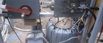
Spotter housing and final assembly
In general, the assembly of a homemade spotter is completed by placing its main elements in the housing and bringing the terminals and controls to the front panel. The housing can be ordered according to a drawing or simply a sketch, or (if possible) manufactured locally. Sometimes craftsmen begin to operate a spotter, the parts and wires of which are simply laid out on a workbench or even on the floor. This option is only suitable for debugging and selecting parameters; such an electrical installation cannot be used in constant mode. Since there are various options for making spotters with your own hands, their body layouts can also be different. For example, if a welding transformer is intended for use outdoors, then in this case the device may take the form of a stable base with a transformer, a terminal block and a separate control system housing.
In other cases, housing options may be different, but the control system elements must always be reliably protected from external influences.
Battery based
A battery powered spotter is suitable for applications where mains power is insufficient, unstable or non-existent and where body work is limited. Typically, this situation arises during body repair of a personal car in a garage cooperative or at a summer cottage. The body of such a homemade spotter may consist of a small support frame for installing the battery, to which a terminal block and a relay that controls shutdown are attached. If this is a one-time job, then you can do without a housing at all by attaching the relay to the battery with a clamp.
Based on a household microwave
To make a spotter with your own hands, a transformer from a microwave is also suitable. In this case, the only limitation is its power, since most microwave ovens are designed to consume less than 1 kW. To solve this problem, you can use two or three transformers connected in parallel. The advantage of such a power source is the small size of the transformers used, which can be placed in a row inside a small-sized housing. The result is a fairly compact and mobile spotter. The only thing you have to worry about is cooling the internal space of such a device.
Scheme
The unit has a not very complex circuit, the main unit of which is welding equipment with a primary winding powered from the mains. When making a spotter, you can use the following energy distribution schemes.
Principal electrical
It consists of power supply equipment, where the voltage on the secondary winding is 12V. To control the current, it is equipped with an additional winding.
Simple
The simplest circuit eliminates the use of a thyristor switch. The supply of current occurs as a result of a short circuit that occurs in the primary winding circuit. Among the disadvantages is the supply of high voltage to the pistol handle, which is unsafe.
Thyristor
Phase shift is used to adjust the current. Suitable for adjusting voltage in alternating electrical circuits. In order for a single-phase network to operate, 2 thyristors are required, which are connected opposite each other. The tuning should be symmetrical and synchronous. Units created using this type of thyristors (semiconductors) have a rigid static characteristic.
How to make an electrode for a spotter
Spotter electrodes and adapters are small cylindrical attachments made of brass, each of which is used to work with certain types of welding fasteners: washers, nails, studs, crimped wire rivets. In stores, each of these elements can cost from 500 to 1000 rubles or more, and for ordinary body work you need at least five or six types of electrodes:
- for rings;
- for spot welding;
- for corrugated wire;
- for welding with carbon electrode;
- for triangular washers;
- for pins and nails.
Making them yourself is not so difficult, but it requires certain skills and the availability of appropriate equipment. Alternatively, you can make only the simplest attachments with your own hands, and order more complex ones in a workshop with turning and drilling equipment.
In battery spotters, batteries with a capacity of 40÷60 Ah are usually used as a power source. If anyone has had to work with such devices, please write in the comments: how quickly the battery discharges and how the quality of welding changes as it discharges.
Among the many accessories for a spotter there is a hook or, as it is more often called, a comb. If anyone doesn’t know, I’ll briefly tell you about the cases in which body repair specialists use a comb when working with a spotter. You can read about how I assembled a spotter from a welding machine, or rather from a welder’s transformer, in this article - “How to make a spotter from a welding machine”
Composition of spot welding spotter control circuit
Additionally, IC2 unloading keys are used with the controller to protect the processor chip from overloads. The IC3 chip was used due to the insufficient number of pins on the processor. Used as a memory register with parallel output and serial input. Depending on the received code, a specific LED turns on. Digital indicators have seven segments connected to a common cathode. The boards are connected into a general circuit by tracks. You can use any LEDs as LED5-10 by selecting the required color.
The sound device must have its own generator with an operating voltage of 5 V. Passive elements can be used of any brand with a nominal accuracy of up to 20%.
To program the controller, you must install the appropriate connector connected to the microprocessor pins: MOSI, MISO, SCK, Reset, Gnd. Firmware can be installed on a programmer or on a computer with a special program installed. There are several options for different programs that help flash processors for various purposes. The main attention is paid to the operation of the device as a spot welding machine. Spotter means “point”.
What is a comb and what is it for?
Imagine a bent car door or fender, usually a deep crease or dent. The question arises - how to properly correct such damage to a body part as efficiently as possible? The answer suggests itself that this needs to be done evenly, and it is advisable to apply force evenly along the entire plane of the crease.
There are also options when working as a spotter - you can weld a “snake” wire, which (from us, in any case) you can’t buy anywhere except ordering through an online store, and it’s expensive. There is an alternative option - to use washers (pictured below).
In short, they are simply welded with a spotter along the entire crease one after another and, using it as a hook point, they are pulled up one by one until the crease comes out. You need to lift it gradually and this is where an accessory for a spotter like a comb comes in handy. This is what a comb sold in specialized stores looks like.
There are two options for using it: with a reverse hammer and a “lifter”.
I’ll tell you how to make a “comb” for a reverse hammer with your own hands, with a minimum of cost and time. The main part of this device, in my opinion, is the hook - it needs to be made correctly, strictly observing the size, it should be the same for all comb hooks, and everything else depends only on your imagination.
Examination
Before use, you must first check the equipment for operational safety. To do this, a preventive examination is carried out:
- clean all elements;
- check the correct insulation of the wires;
- clean the deformed surface;
- inspect the reliability of fastening of all parts;
- ground the device.
Only after carrying out the above steps, you can start using the unit.
Attention! If you do not follow safety rules, you may receive a severe electric shock.
Making a comb for a spotter
So, let's do everything in order. What do we need, or rather, what materials and tools do we need?
- grinder with cutting and grinding wheel,
- drill,
- drills 13 and 8mm,
- round file,
- welding machine,
- hammer,
- core
- A metal rod 30 cm long, 13-14 mm in diameter, best if it is red-hot iron.
- A strip of sheet iron 3-4 mm thick, 3 cm wide, length - from 40 cm.
- Bolt with nut diameter 8 mm.
- Tube Ø15mm, length about 10 cm.
This website uses its own and third-party cookies to analyze and improve its performance.
By continuing to browse it, you agree to its terms of use. Read more.
Personal data privacy policy
This Personal Data Privacy Policy (hereinafter referred to as the Privacy Policy) applies to all information that the Sam Avtomaster website, located on the domain name sam-avtomaster.com, can receive about the User while using our website.
This Privacy Policy applies only to the Sam Automaster website. The Site guarantees that it will not damage the User’s computer or infect it with viruses.
The site administration does not verify the accuracy of the personal data provided by the User when sending them an email.
Visitor identification
To view information on the Sam-Avtomaster.com website, registration with personal data is not required. When a User accesses our website, no personal information is collected. It is possible to browse the site anonymously.
The email address, as well as the postal address specified when filling out the fields of the comment form, order form and contact form are not shown to other site visitors. We may store comments, emails sent by Users on the server to process requests, answer questions and improve site services.
Personal data permitted for processing under this Privacy Policy is provided by the User by filling out the contact form, order form and comment form on the site and may include the following information:
- Full name of the User;
- Email address (e-mail);
- Postal code and address;
Cookie
When a User visits a site, one or more cookies are sent to their computer. This is a small file that contains character sets and allows you to identify the User's browser. We use cookies to improve our service by storing user preferences and tracking trends in user behavior, such as searches and advertising. Most browsers are initially configured to accept cookies, but the User can completely disable the use of cookies or set up notifications when they are sent. However, without cookies, some site features may not function properly.
Logging
Each time you visit the site, our servers automatically record information that the User's browser transmits when visiting web pages. Typically, this information includes the web page requested, the computer's IP address, browser type, browser language settings, and the date and time of the request.
Links
Links on this site may be in a format that allows us to track whether visitors use them. This information is used to improve the quality of our advertising.
Changes to the privacy policy
The site administration has the right to make changes to this Privacy Policy without the consent of the User.
The new Privacy Policy comes into force from the moment it is posted on the Automaster website, unless otherwise provided by the new edition of the Privacy Policy.
All suggestions or questions regarding this Privacy Policy should be reported to the Site Administration through the CONTACTS page.