Most modern mobile phones, smartphones, tablets and other wearable gadgets support charging via a mini-USB or micro-USB USB socket. True, a single standard is still far away and each company is trying to do the pinout in its own way. Probably they should buy the charger from her. It’s good that the USB plug and socket itself were made standard, as well as the supply voltage of 5 volts. So, having any charger adapter, you can theoretically charge any smartphone. How? Explore USB pinout options and read on.
Pinout diagrams for charging tablets
Almost any tablet computer requires a large current to charge - 2 times more than a smartphone, and charging through the mini/micro-USB socket in many tablets is simply not provided by the manufacturer. After all, even USB 3.0 will not provide more than 0.9 amperes. Therefore, a separate nest (often round type) is placed. But it can also be adapted to a powerful USB power source if you solder an adapter like this.
Useful: Car rear view camera wire pinout
Can it be charged?
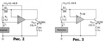
If peripherals are connected to the device via OTG, then it will have to power it, which can significantly reduce the overall operating time of the device from the built-in battery. In this regard, many people wonder whether it is possible to recharge such a device through an external source. This is possible, but this requires support for a special mode in the device, as well as a separate wiring of the USB connector for charging.
In fact, the charging mode is most often provided by modern gadget developers, but not everyone allows such a procedure. It should be noted that to switch to this charging mode, a separate USB connector wiring diagram must be used, in which the contacts are closed through a separate resistor.
Pinout of micro usb charging connector
- The USB bus connector appeared around the beginning of 1990, and its main purpose was to be used in household radio equipment. Today, the micro USB connector has become extremely popular not only in household devices, but also in professional multimedia devices. However, its “everyday” origins are clearly visible in the fact that these plug-in format connectors are installed on almost any audio-video equipment, without exception.
The first connecting connectors differed from modern ones in their large sizes, although its socket was normally installed in small-sized portable devices. Over time, the sizes of USB connectors have acquired compact forms in various variants, such as MINI-USB, MICRO-USB and simply USB. These types of connecting devices made it possible to carry out its main functional purpose. At the same time, they differed significantly in size and ease of use from the earlier created analogue.
Device and pinout of micro usb charging connector
The micro usb connecting device consists of five contact pads, an insulated mounting wire is connected to each pad. For precise orientation of the connector when connecting to the mating part of the connector, a special chamfer is made on the edge of its upper shielding part. The contact pads of the connector are numbered from one to five, which are read from right to left. For clarity, this is shown in the picture below. The wiring diagram for the micro USB connector, as well as the purpose of its contacts isolated from each other, are shown in the table:
Micro USB pinout by wire color
The shielding shell also serves as a wire, but is not soldered to a separate contact pad.
Modern connecting devices such as micro USB connectors have fairly good performance characteristics and a relatively low price. Therefore, given the availability of a huge number of different connecting wires of this type in the trade, repairs of such auxiliary equipment are carried out extremely rarely. But still, if you have to replace a defective connector socket, then pinout the micro USB connector will not cause much trouble. Structurally well-made micro USB connectors, even despite their miniature dimensions, they will not allow you to make serious mistakes in installation.
Charger port classification
- SDP (Standard Downstream Ports) – data exchange and charging, allows current up to 0.5 A.
- CDP (Charging Downstream Ports) – data exchange and charging, allows current up to 1.5 A; hardware identification of the port type (enumeration) is performed before the gadget connects the data lines (D- and D+) to its USB transceiver.
- DCP (Dedicated Charging Ports) - charging only, allows current up to 1.5 A.
- ACA (Accessory Charger Adapter) - PD-OTG operation in Host mode is declared (with connection to PD peripherals - USB-Hub, mouse, keyboard, HDD and with the possibility of additional power supply), for some devices - with the ability to charge PD during OTG- sessions.
Cable Feature
The main feature that distinguishes the wiring of a USB connector in the OTG format is that in the plug, pin 4 must be connected to pin 5. In a standard data cable, nothing is soldered to this pin at all, but this plug is called USB-BM micro. It is for this reason that you need to get to the fourth contact, and then use a jumper to connect it to the GND wire. After this procedure, the plug will be renamed USB-AM micro. It is the presence of a jumper between these contacts in the plug that allows the device to determine that some kind of peripheral device is about to be connected to it. If the device does not see this jumper, it will act as a passive device, and any flash drives connected to it will simply be completely ignored.
How to remake a plug with your own hands
Now you have a pinout diagram for all popular smartphones and tablets, so if you have the skill to work with a soldering iron, there will be no problems converting any standard USB connector to the type your device needs. Any standard charging that is based on the use of USB involves the use of only two wires - +5V and a common (negative) contact.
Just take any 220V/5V charging adapter and cut off the USB connector from it. The cut end is completely freed from the shield while the remaining four wires are stripped and tinned. Now we take a cable with a USB connector of the desired type, after which we also cut off the excess from it and carry out the same procedure. Now all that remains is to simply solder the wires together according to the diagram, after which each connection is insulated separately. The resulting case is wrapped on top with electrical tape or tape. You can fill it with hot glue - also a normal option.
Bonus: all other connectors (sockets) for mobile phones and their pinouts are available in a single large table -
.
USB 2.0 pinout
USB 2.0 is the most common connector. Supported on all OS (which cannot be said about 3.0). It is very convenient, because its wire is thin and long. The current is 500 mA, which is quite low, since there are already more advanced USB models on the market that provide fast data transfer.
Now the question remains, how does this device function? The work occurs through an asynchronous serial protocol, which implies that there is no common clock between the addressee and the sender. Any device that connects to a USB port works through this protocol. If the microcontroller or microprocessor has the ability to support a USB host, then it allows us to connect any USB device, such as a keyboard, etc.
To make communication between this device and the host (uP or uC) when a USB device is connected, first the device descriptor tells the host what the vendor ID and product ID is, which is used to load a specific driver for the device, then comes the configuration descriptor, which mainly used to determine power consumption values, then there is an interface descriptor, the host device can be a printer, scanner or USB flash drive, this descriptor is responsible for determining what kind of device it is, finally there is an endpoint descriptor; this descriptor is used to determine the speed of the transfer type, the throughput of the packet size, etc. There are four endpoints for a low-speed USB 2.0 device and 16 for a high-speed USB 2.0 device.
Let's talk about D. There are two of them, (+ and -), since USB C is supposed to be returnable. If you connect the plug both ways, it will be considered a valid USB 2.0 connection because USB 2.0 does not do pinning negotiation. Rotate the plug 180 degrees and these pins are connected in the same order. Your board should connect both together for maximum connectivity.
There is no identification pin, as it is only used on plugs. In USB C, the CC pins handle this, and connecting them to GND with a 5K resistor creates OTG HOST mode on the opposite side of the connection.
USB 2.0 has 4 pins.
On this pinout you can see the distribution of pins on the motherboard. It can be seen that the red contact is 1 and 2 divisions, white is 3 and 4, green is 5 and 6, black is 7, 8, 10. There is no 9 contact here. The contacts are located below each other.
Types of connectors
The types of USB connectors depend on the function performed and the speed at which data is transferred. Thanks to the existence of several types of USB connectors, extended functionality is covered, which allows the user to simplify the connection between the computer and the device (mouse, keyboard, iPad, MFP, scanner, etc.).
When choosing a USB, you need to pay attention to the type of USB cable, the function and transfer speed
Type-A
This USB connector still ranks among other types. The user encounters such cables every day. These include storage devices (flash drives), USB cables from chargers. Most cameras and routers are equipped with this type of USB cable. It is reliable and safe to use. It is harder to break and disable it.
This type is equipped with a built-in security system. The cable can only be inserted into the computer on one side. If you turn the cord over, it simply will not fit into the connector. Which is an advantage. Especially when using the cable by inexperienced users.
Type-B
Type B is used to connect peripherals - MFPs, scanners, faxes, and so on. A type B cable is not always supplied with the device and often you have to purchase it yourself. There are 2 types of USB type b cables: micro- and mini-USB.
A type of mini USB is an outdated USB port. This is an early version of the micro type. The use of mini USB is kept to a minimum. But still, sometimes there are devices that use this type of connection. You can see what micro USB looks like in the photo.
Micro USB connector type B is a smaller version of connector b (there is a similar type of connector A - Micro USB Type A). Micro USB connector is used in most mobile devices (except Apple). Apple has its own connector.
Type-C
It was invented relatively recently (first appeared on the market in 2014). The USB Type C connector is at the beginning of its development and is not actively used. Has reduced dimensions of both inputs. First used by Apple, which continues to improve this development today.
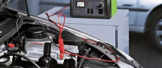
Charging the battery via Micro USB
In addition, it supplies a 5-volt power supply to charge the battery of wearable gadgets. Since almost all modern lithium batteries have an operating voltage of 3.7 V, the 5 V supplied via Micro-USB is excellent for replenishing energy. True, not directly to the battery, but through the charger converter.
I’m glad that the connector pinout is the same for all smartphone manufacturers - Samsung, LG, Huaway and others. Thus, a 220 V charger-adapter from one phone is most often suitable for charging another without changing the pinout.
The main advantage of the Micro-USB connector over other types is the ability to connect Plug&Play devices without the need to restart the computer or manually install drivers. Devices can be connected while the computer is running and disconnected without having to press any buttons.
Conclusions and useful video on the topic
The video below explains the main points of pinout of connectors of the 2.0 series and others, and visually explains individual details of the production of soldering procedures.
Having complete information on the pinout of Universal Serial Bus connectors, you can always cope with a technical problem associated with conductor defects. This information will also come in handy if you need to connect some digital devices in a non-standard way.
Would you like to supplement the above material with useful comments or valuable tips on do-it-yourself desoldering? Write comments in the block below, add, if necessary, unique photographic materials.
Maybe you still have questions after reading the article? Ask them here - our experts and competent site visitors will try to clarify unclear points.