If you want to ensure that your car’s battery lasts a long time and reliably, and starts the engine in any of the most difficult climatic conditions, then it is important to maintain the battery in a timely manner. A car charger (CA) is a device that recharges batteries as the unit's capacity decreases. The result is a confident start of the car engine even after a long period of inactivity in subzero temperatures.
Below we will take a closer look, and then consider the TOP of the best chargers! But if you already know everything, check out the prices on Yandex Market, this will help you finally make your choice.
Primary requirements
Homemade devices, unlike factory ones, require a slightly different approach to operation. Most of them lack many components that help with charging and increase safety. This happens mainly because craftsmen, having no experience in installing complex electronic circuits, strive to simplify the design.
If there are no automatic control and emergency shutdown devices, the process must be constantly monitored. Leaving the device running unattended is dangerous: there is a risk of battery damage and even fire. Therefore, in a charger made independently, it is advisable to provide components for safe autonomous operation.
They must provide:
- output voltage stability;
- disconnection from the battery when the charging current or voltage is exceeded;
- self-locking - after an emergency shutdown, the device cannot start on its own;
- protection against incorrect polarity connection.
Helpful advice
When using devices without automatic battery charge control, you can use the simplest network, daily relay made in China. This will eliminate the need to monitor the time the unit is disconnected from the network.
The cost of such a device is about 200 rubles. Knowing the approximate charging time of your battery, you can set the desired shutdown time. This ensures that the electricity supply is cut off in a timely manner. You can get distracted by business and forget about the battery, which can lead to boiling, destruction of the plates and failure of the battery. A new battery will cost much more
Necessary parameters for DC charging
It has already been proven that it is necessary to charge automobile lead acid batteries (mostly these are the ones found in cars) using a current not exceeding 10% of the capacity of the entire battery.
So, in the case of a battery capacity of 55 A/h, the maximum supply of charging current should be 5.5 A. Using this principle, the maximum current for any battery is calculated. You can even slightly reduce the current supply, but in this case the charging process will be a little slower. Charge accumulation will occur even if the charge current is closer to 0.1 A. But in this case, it will take a very long time to restore the capacity.
The minimum battery charging time at a current level of 10% of the charge is 10 hours, but this is in the case of a complete battery discharge, which is unacceptable. Therefore, the actual time to full charge is affected by the depth of discharge.
To calculate the approximate time to full charge, you should find out the difference between the maximum charge (12.8 volts) and the current voltage. If you multiply this figure by 10, you can get approximately the time in hours.
general characteristics
To properly maintain the battery and extend its service life, recharging is required when the voltage at the terminals drops below 11.2 V. At this voltage, the engine will most likely start, but if parked for a long time in winter, this will lead to sulfation of the plates and, as a result, a decrease in capacity batteries. When parked for a long time in winter, it is necessary to regularly monitor the voltage at the battery terminals. It should be 12 V. It is best to remove the battery and take it to a warm place, while not forgetting to monitor the charge level .
The battery is charged using constant or pulsed current. When using a constant voltage power supply, the current for proper charging should be one tenth of the battery capacity . If the battery capacity is 50 Ah, then a current of 5 amperes is required for charging.
To extend the battery life, battery plate desulfation techniques are used. The battery is discharged to a voltage of less than five volts by repeated consumption of a large current of short duration. An example of such consumption is starting a starter . After this, a slow full charge is carried out with a small current within one ampere. Repeat the process 8-9 times. The desulfation method takes a long time, but according to all studies it gives good results.
It must be remembered that when charging, it is important not to overcharge the battery. The charge is carried out to a voltage of 12.7-13.3 volts and depends on the battery model. The maximum charge is indicated in the documentation for the battery, which can always be found on the Internet.
Overcharging causes boiling , increases the density of the electrolyte and, as a result, destruction of the plates. Factory charging devices have charge monitoring and subsequent shutdown systems. to assemble such systems yourself without sufficient knowledge in electronics.
Homemade battery charger
There are many car charger circuits. For most implementations, parts such as transformers soldered from old radio equipment and computer power supplies are suitable.
Charging with continuously adjustable current
The circuit is a little more complicated, but all the details are available. The device charges 12-volt batteries with a capacity of up to 120 Ah. The type of charging current is pulsed, a thyristor is used. The regulator smoothly changes the amount of charging current, but at the same time a step switch is provided. The mode is controlled using a 30 A dial ammeter.
A homemade resistor R1 is needed to limit the current. Copper or nichrome wire with a diameter of 0.8 mm is suitable for its manufacture. You will need a small indicator lamp E1, rated for 24-36 V.
The output voltage on the step-down transformer is 16-18 V, the current is 15 A. They look for a device with such characteristics or make it with their own hands from a suitable device with a power of 300 W. Only the primary winding is left, the secondary winding of 42 turns is wound with insulated wire, cross-section 6 mm².
The circuit requires a KU202 thyristor with the letter index V-N. For cooling, a radiator is used, the dispersion area of which is from 200 cm². You will also need a VD1 diode of any type with a reverse voltage of 20 V and a current of 200 mA.
Set up the device by calibrating the ammeter, connecting a known good one as a control one. For the load, instead of the battery, car light bulbs are connected, the total power of which is 250 W.
Charging from a computer power supply
An old PC power supply with a TL 494 controller makes a charger with good performance. It has an adjustable voltage and the ability to adjust the current up to 10 A.
According to the diagram, some changes are made to the power supply unit removed from the computer:
- All the wires on the power buses are cut off, leaving only the yellow and black ones.
- Conductors of the same color are connected to each other. The black harness is the negative contact of the charger, the yellow one is the positive one.
- The printed tracks to legs 1, 14, 15, 16 of the microcircuit are cut.
- To regulate the voltage, install a variable resistor of 10 kOhm, charging current - 4.4 kOhm.
They are assembled using the hinged mounting method, using wires with a minimum cross-section of 4 mm². Install a voltmeter, ammeter, connect wires with clamps.
A 0.1 Ohm resistor with a power of 10 W or more located at the bottom of the circuit is made of copper or nichrome: select the desired wire length by measuring the resistance. Resistors C5-16MV or 2 5WR2J connected in parallel are also suitable. The rest are of any type.
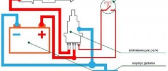
Protection
UZ for a battery is like armor for a tank, so let's start with it. It is advisable to make the ultrasound for a homemade battery charger, of course, simpler. Further, it is also advisable to build the battery autonomously, so that through it you can connect the battery to any charger whose circuit you like, or which you already have. And lastly, the ultrasound must operate as clearly and quickly as possible in order to be able to use it in charging circuits for modern batteries with sealed banks.
Ineffective car battery protection schemes
The simplest protection against polarity reversal using Schottky diodes (on the left in the figure) will not save you from overcharging extra current or from incorrectly connecting a serviceable undercharged battery. Unless by burning an expensive diode assembly. If the battery is “new, good”, then until your hands reach the “new, good” charger, the integrated protection according to the diagram on the right can help out; it can be built into an existing homemade laboratory IP.
This circuit uses the slow response of the battery to a voltage surge and the hysteresis of the relay: their release current (and voltage) is 2.5-4 times less than the operating current/voltage. Any battery charger is turned on only with a connected battery. The relay is an alternating current one with an operating voltage of 24 V and a current through the contacts of 6 (9, 12) A. When the charger is turned on, the relay is activated, its contacts close, and the charge begins. The voltage at the output of the transformer drops below 24 V, but at the output of the charger there remains 14.4 V, set in advance under load R3 in the voltage stabilization circuit. The relay is still holding, but suddenly there is an extra current, the primary voltage will drop more, the relay will release and the charging circuit will break.
This memory has serious disadvantages. Firstly, there is no protection against a voltage surge at the output due to polarity reversal of a depleted battery. Secondly, there is no self-locking: from the extra current the relay will clap and clap until the contacts burn out. Thirdly, unclear operation: any relay due to undervoltage on the winding releases with contact chatter. Therefore, trying to introduce control of the operating current into this circuit is pointless. And finally, the relay and transformer T1 must be matched to each other, i.e. The repeatability of this device is close to zero.
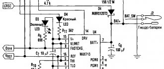
The ultrasound scheme, which fully complies with the above requirements, is shown in Fig.:
A simple scheme for protecting a car battery from overcharging, overvoltage and reverse polarity
The charging current flows through the normally closed contacts of relay K1, which greatly reduces the likelihood of them burning. Winding K1 is connected via a diode “or” logic circuit to the overcurrent protection module (R1, VT1, VD1), the overvoltage protection module (R2, R3, R4, VT2, VD2) and the self-locking circuit K1.2, VD3; the overvoltage response threshold K1 is set by R3. This ultrasound has only one drawback; it needs to be adjusted using a ballast load and a multimeter:
- Solder (or not yet solder) K1, VD2 and VD3.
- Instead of winding K1, turn on a multimeter set to measure a voltage of 20 V.
- Instead of a battery, connect a resistor of at least 25 W with a resistance of 2.4 Ohms for a charge current of 6 A, 1.6 Ohms for a charge current of 9 A and 1.2 Ohms for a current of 12 A; it can be wound from the same wire as R1.
- A voltage of 15.6 V from the charger is supplied to the input. The multimeter will show the voltage (current protection has tripped), because resistance R1 is selected with a slight excess.
- Reduce the charger voltage slightly until the multimeter shows 0. Record the resulting value of the charger output voltage. The alternative is a constant memory voltage and labor-intensive adjustment of R1.
- VT1 is unsoldered, K1 and VD2 are soldered in place, the R3 engine is placed in the lowest position according to the diagram.
- The charger voltage is increased until the load reaches 15.6 V.
- Smoothly rotate the engine R3 until K1 is activated.
- Reduce the voltage of the charger to the previously recorded value.
- VT1 and VD3 are soldered into place - the circuit is ready for final tests.
- A serviceable, undercharged battery is connected through an ammeter; next to it is a multimeter set to voltage.
- The test charge is carried out with continuous monitoring. When the multimeter shows 14.4 V on the battery, the content current is detected. Most likely it will be normal for this battery (see above); preferably closer to the lower limit.
- If the content current is too high, reduce the voltage of the charger a little more.
Battery charging requirements
Before carrying out the procedure for making a homemade battery charger, you must pay attention to the following requirements:
- Providing a stable voltage of 14.4 V.
- Device autonomy. This means that a homemade device should not require supervision, since the battery is often charged at night.
- Ensuring that the charger turns off when the charging current or voltage increases.
- Reverse polarity protection. If the device is connected to the battery incorrectly, the protection should be triggered. For implementation, a fuse is included in the circuit.
Polarity reversal is a dangerous process, as a result of which the battery may explode or boil. If the battery is in good condition and only slightly discharged, then if the charger is connected incorrectly, the charging current will increase above the rated one. If the battery is discharged, then when the polarity is reversed, an increase in voltage above the set value is observed and, as a result, the electrolyte boils.
Wires for connection
To connect any charger, as a rule, red and black wires are used, red is positive, black is negative.
When choosing cables to connect a charger or starting device, you must select a cross-section of at least 1 mm2.
Attention. Further information is provided for informational purposes only. Whatever you want to bring to life, you do at your own discretion. Incorrect or inept handling of certain spare parts and devices will cause them to malfunction.
Having looked at the available types of chargers, let’s move on directly to making them ourselves.
Circuit diagram of a charger for a car battery
To assemble a homemade charger you need at least soldering skills, nothing more. Here are several circuit diagrams of a car battery charger that can be assembled in a couple of hours.
Simple circuits
Here are 3 circuit diagrams for a simple car battery charger. Perhaps you already have all the necessary components or you can buy them for next to nothing at a flea market.
With diode bridge
This option is better suited for a car battery. DM is already a full-fledged voltage equalizer.
The charger for a car battery is assembled in the same way, but instead of a diode, a bridge is installed. From its minus, the wire goes to the fuse after the transformer.
You can buy a diode bridge or solder it yourself. To do this you only need 4 diodes. The diagram looks like this. The voltage is still pulsating, which is not good for batteries.
With diode bridge and capacitor
This is what a proper transformer charger looks like. A capacitor of 25-50 volts and 5000-6000 microfarads is placed between plus and minus.
The capacitor receives voltage and releases it, but already equalized and without ripple.
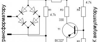
Adjustable circuits
If you want a homemade car battery charger to work correctly, you need a regulator. A regular tuning (variable) resistor of 4.7 kilo-ohms can handle this.
There are also 3 transistors in the circuit. Their location and number are signed, so there will be no problems. All you have to do is come to a radio store and show them the names. They are necessary for the resistor to work correctly.
Transistors need at least passive cooling, so it is better to attach an aluminum plate or install a cooler to their radiators.
Comment. In the diagram, an ammeter is installed in the gap of transistor P210 and the second fuse. With current and voltage adjustment, there is no need for it, since only the voltage needs to be adjusted. Therefore, it is better to put a voltmeter in its place.
A detailed video can be viewed below.
How to find out the battery status?
The need to charge a car battery depends on the charge level. And the testing method, which is usually called “twist/no-twist,” is not a good method. If the battery “does not spin”, for example, before moving off you cannot start the car at all, the “does not spin” condition is critical and can have extremely negative consequences for the battery itself.
The most effective and safest method is to measure the voltage with a simple tester. So, at an air temperature of about 20 degrees, the dependence of the degree of charge on the voltage at the terminals of a battery disconnected from the load looks like this:
- 12.6-12.7 - battery is fully charged;
- 12.3-12.4 - charge level is about 75%;
- 12.0-12.1 - about 50%;
- 11,8-11,9 — 25%;
- 11.6-11.7 - battery is discharged;
- if the indicator is below 11.6 V, it means a deep discharge.
All of the above indicators are measured in volts.
The 10.6 volt gauge is critical and if the level drops any further the battery, especially if it has been serviced for a long time, will simply fail.
WHAT WE TESTED AND WHERE
The tests were carried out in the laboratory of the Federal State Institution 3 Central Research Institute of the Ministry of Defense of the Russian Federation for three months. A long-term test of the devices’ ability to compensate for a drop in charge was carried out on batteries with an energy capacity of 55, 75 and 90 Ah at temperatures of -20; 0; +25 ºС. The tendency to overheat was assessed when working with batteries from 75 to 190 Ah, setting the maximum possible load for each device. For each product, they checked the “fool resistance” - they used polarity reversal, etc. When arranging in places, they took into account the declared parameters, workmanship, correctness of instructions and ease of use.
Read also: DIY table saw
Correct charging
There are two methods of charging a car battery - constant voltage and constant current. Each has its own characteristics and disadvantages:
Battery condition assessment table.
Frequently Asked QuestionsWhat is the main function of a car charger?
All chargers perform one job - convert alternating voltage 220 V into direct voltage - 13.8-14.4 V.
What do you need for a simple homemade charger?
To make a simple charger, you only need two components - a transformer and a rectifier.
How many fuses do you need for a homemade car charger? It is recommended to install one of them on the “positive” terminal of the diode bridge. This fuse must be rated for a current of no more than 10 A. The second fuse (0.5 A) must be installed at terminal 2 of the transformer.
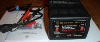
BAT_5284-utv
Many people are not even aware of the existence of such devices. Everyone knows about chargers, but what are they? And in what cases may they be needed?
We will return to the terminology later, but these “recharges” are needed for this reason. Imagine a car sitting in a garage for weeks without moving. When it is suddenly needed urgently, it turns out that the battery is so low that it cannot turn the starter. What if this happens all the time?
Cars that are on exhibition stands often find themselves in a similar situation. Their audio system is playing, the lights are on, but the engine is not running. So thin wires stretch under the hood, feeding the standard battery of the car from an external source.
Large currents are not needed: it is enough to compensate for the consumption of standard microcontrollers, as well as the security system and telematics. Modern gadgets have a modest appetite - tens of milliamps, despite the fact that their analogues from previous years of production sometimes consumed an order of magnitude more.
It would seem that connect the charger - and there are no problems! But not every “charge” is designed for continuous operation for weeks, or even months. It’s another matter if the manufacturer indicates a similar possibility of using their product. These are the devices we decided to test in real conditions - for several months.
Of the eight purchased products, only two are pure “recharges” - Tornado and Moratti. The rest are “chargers” that promise not only to revive dead batteries, but also to maintain their charge at the proper level. It is this function that we evaluated during the tests.
What other charger options are there for batteries?
Let's consider several more options for autonomous chargers.
Using a laptop charger for the battery
One of the easiest and fastest ways to revive a dead battery. To implement a battery revitalization scheme using laptop charging, you will need:
- Charger for any laptop. Charger parameters are 19V, current is about 5A.
- 90 W halogen lamp.
- Cable connection with terminals.
Let's move on to the implementation of the scheme. The lamp serves to limit the current to the optimal value. You can use a resistor instead of a light bulb.
A laptop charger can also be used to revive a car battery.
It is not difficult to assemble such a circuit. If you do not plan to use the laptop charger for its intended purpose, you can cut off the plug and then connect the clamps to the wires. First, use a multimeter to determine the polarity. The flashlight is connected to the circuit going to the positive pole of the battery. The negative terminal of the battery is connected directly. Only after connecting the device to the battery can voltage be applied to the power supply.
DIY charger from a microwave oven or similar devices
Using the transformer block, which is located inside the microwave, you can make a battery charger.
Below are detailed instructions for making a homemade charger from a microwave transformer block.
- It is necessary to remove the transformer unit from the microwave.
- Remove the secondary winding, then replace it with insulated wire with a cross-section of more than 2 mm2.
- Determine the required number of turns of the insulated wire. You can select the desired value experimentally. To do this, you need to wind 10 turns and then measure the output voltage. For example, if its value is 2V, it will take about 70 turns to reach 14.5V. The output voltage will depend on the size of wire used.
The winding has been removed from the microwave transformer unit - To implement the circuit, you will need a diode bridge and a powerful capacitor.
- If desired, you can include an ammeter in the circuit, which will show the current.
Connection diagram of a transformer, diode bridge and capacitor unit to a car battery
The device can be mounted on any base. It is important that all structural elements are reliably protected. If necessary, the circuit can be supplemented with a switch and a voltmeter.
Transformerless charger
If the search for a transformer is stopped, you can use a simpler circuit without step-down devices. Below is a circuit that allows you to implement a battery charger without using voltage transformers.
Connection diagram for charger without voltage transformer
Capacitors designed for a voltage of 250 V act as transformers. At least 4 capacitors should be included in the circuit, placing them in parallel. A resistor and an LED are included in the circuit in parallel with the capacitors. The role of the resistor is to suppress the residual voltage after disconnecting the device from the network.
The circuit also includes a diode bridge designed to operate with currents up to 6A. The bridge is connected to the circuit after connecting capacitors and wires going to the battery for charging to its terminals.
STORAGE? RECHARGING? COMPENSATION?
The multi-month marathon ended successfully: not a single device asked for mercy, not a single battery complained of poor service. “Fool protection” is also at its best: the products are not afraid of polarity reversals and other provocations. At the same time, not everyone liked it - we spoke about this topic in detail in the captions of the photo gallery. We also note that all devices provide recharging in 20-degree frost - even those that, judging by the instructions, are not at all frost-resistant.
But you need to be more polite with wires - they lose their flexibility right before your eyes.
Is it worth looking for simple chargers in stores, or is it better to buy a multifunctional charger? We believe that the second option is preferable: the difference in price is not astronomical, and a full-fledged charger in the household will not hurt. In addition, they are almost always on sale, and exotic “smaller brothers” need to be looked for via the Internet.
STARTED AZU-108 8 7 6
Automatic pulse charger , St. Petersburg
Approximate price, rub. 1280
Temperature range, ºС 0…+40
Energy capacity of rechargeable batteries, Ah 3–110
The cute device was unpleasantly jarring to the eyes with the illiterate “A/h” inscriptions on the front panel, in the instructions and on the packaging. There is no such unit of measurement in nature - there is Ah. The manufacturer's requirements for the temperature conditions of the device's operation - from 0 to 40 ºС - were not encouraging: how to maintain the battery charge if it is frosty outside? The execution is sloppy: the glued switches are loose. In general, the device is functional, but I don’t want to recommend it.
Tornado 3 A.02
Charging automatic storage device for batteries , Togliatti
Approximate price, rub. 860
Temperature range, ºС —20…+40
Energy capacity of rechargeable batteries, Ah up to 75
The device promises to maintain the working condition of the battery “for as long as desired”, without being a full-fledged charger (except for batteries with an energy capacity below 10 Ah). Outwardly, it resembles an amateur radio design in a housing from a time relay for photo printing. The element base is a quarter of a century old. The product successfully passed all electrical tests (overheating tests were carried out with a 75 Ah battery). However, the overall impression is rather negative.
Moratti 01.80.005
Device for recharging batteries , China
Approximate price, rub. 600
Temperature range, ºС not lower than -10
Energy capacity of rechargeable batteries, Ah 10–250
The device is not intended for charging batteries, but to maintain battery performance during long-term storage and infrequent use. Withstands long-term operation calmly; The overheating test was carried out on a battery with an energy capacity of 190 Ah. There are no comments about the technology, but I didn’t like the description: what are “gel” batteries? Maybe they meant gel ones?
SONAR U3 207.03 3
Charger , St. Petersburg
Approximate price, rub. 1500
Temperature range, ºС —5…+35
Energy capacity of rechargeable batteries, Ah 10–180
The charger provides storage mode with self-discharge current compensation. Unfortunately, the lower temperature limit is only -5 ºС. In other words, the device is not designed for winter operation in an unheated garage. The case does not overheat during operation (the test was carried out with a battery with an energy capacity of 170 Ah). There are no complaints about the technology, but the price seemed overpriced.
AIRLINE ASN‑5 A‑06
Charger, Russia - China
Approximate price, rub. 1050
Temperature range, ºС no data
Energy capacity of rechargeable batteries, Ah up to 65
Provides a charging mode for the battery installed on the vehicle. The overheating test was carried out on a battery with an energy capacity of 65 Ah; no reasons for comment were found. It copes with recharging successfully. Unfortunately, the mythical unit of measurement A/h is found in the description of this device.
HEYNER, AkkuEnergy Art. 927130
Charger, Germany
Approximate price, rub. 6000
Temperature range, ºС no data
Energy capacity of rechargeable batteries, Ah 30–190
A charger designed for long-term connection to the battery, regardless of the season. All tasks were completed without problems. The overheating test was carried out with a 190 Ah battery. Disadvantages include an abstruse description with poor translation and an unappetizing price.
1–2. SMART POWER SP‑2N BERKUT
Compact universal charger , Russia - China
Approximate price, rub. 1150
Temperature range, ºС —20…+50
Energy capacity of rechargeable batteries, Ah 4–80
It can also be used for seasonal battery storage, remaining connected to the network for several months. The long-term operation mode is tolerated calmly; The overheating test was carried out with a 90 Ah battery. “Fool resistance” is normal, there are no comments on the work.
1–2. SOROKIN® 12.98
Universal battery charger, Russia
Approximate price, rub. 3000
Temperature range, ºС —20…+50
Energy capacity of rechargeable batteries, Ah 6–160
Full charger. Can be connected to a car battery for a long time - for winter storage and year-round use. It does not overheat during operation (the test was carried out with a 170 Ah battery). No comments. It's just a little expensive.