Without this, the mosfet will not open and the voltage on the transformer will be zero. The second pin is connected to a separate, third connector.
If you remove the plug from the socket several times in a row, each time in a different way: once, the sound disappears and the battery charging process begins and charges the battery completely as it should. The total voltage of such a composite battery is 14.4 volts.
The need for a home workshop of hand-held power tools is obvious - it will help with repairs, construction and many other matters that arise in everyday life. In some cases, switching power supplies can be introduced to reduce charging dimensions. Repair of a charger for traction lead-acid batteries (for electric bicycles)
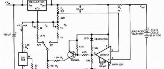
The power of batteries is determined by their voltage multiplied by their capacity, measured in ampere-hours. Charger circuit The operating principle is as follows: 1.
I had to tinker with resistors R6 and R5, but the Internet helped me understand the original resistance values; the color stripes either turned black or completely burned out!
I'll give it here. The second pin is connected to a separate, third connector.
WorkBlog about electronic devices, electronic components, electronic devices, repair of equipment and electronics, solving developer problems. You need to know the location of control points and their standard measurement values.
The power part of the charger consists of a GS power transformer
Repair of the Interskol 12 volt screwdriver charger, on the SD C804S board
Troubleshooting
I opened the charger in front of him and saw a burnt circuit board under a burnt resistor, some kind of cracked low-power transistor, a blown fuse. What immediately caught my eye was the “radiator” of the power transistor, or rather its absence, because instead of it there was a small iron plate on which the power switch was actually attached. I drew the owner’s attention to this deliberate factory mistake (possibly for profit) and suggested installing a real radiator instead, and also drilling more ventilation holes in the device’s body, since I didn’t have a small fan and the owner did not want to move a large radiator outside the case. Having agreed on the price, they shook hands.
to contents ↑
Repair
After desoldering one leg from the board, the following were finally determined to be faulty: power field-effect transistor V5, almost broken low-resistance resistor R5 (about 2.5 MOhm, with a norm of 3.3 Ohms) in the source circuit of the field-effect transistor, broken low-voltage diode V8 in the PC817 optocoupler harness, burnt out resistor R6 in the circuit of transistor V6 and the oscillator transistor V6 itself.
Broken diode
Crack in the resistor due to overheating
Burnt parts
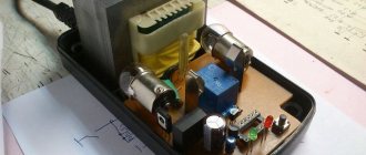
Board with soldered parts
The problem was rooted in the high-voltage power part of the circuit. To make it clear and easier for you to repair, “what goes where”, etc. I decided to draw the faulty part of the circuit from the board.
to contents ↑
Diagram drawing technique
Using my old method. Let me explain briefly, it is simple. I use a gel pen to draw elements on the side of the board tracks so as not to get confused and not have to go back to the beginning every time.” After that, I draw a draft on paper, and then the final finishing version.
Method of drawing the circuit from the board side
Draft version of the circuit drawing
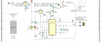
Diagram of the high voltage part of the Bosch AL 1115 CV
The V5 STP5N80ZF was not found, but an analogue of the K3565 (900V, 15A in pulse mode) was found. By and large, any similar field device will do, the main thing is that it is not weaker in terms of impulse current and voltage. The low-power transistor V6 2N3904 of the autogenerator was replaced with a domestic KT3102A, in a metal case and with gold-plated legs! It’s nice to remember and use cool Soviet transistors in a new way!
