The ventilation system is a very complex system that consists of many functional components, from air ducts to ventilation units. Considering that for the correct operation of such a system many indicators are taken into account, the implementation of any more or less serious project of a ventilation and air conditioning system will not be complete without the use of measuring instruments. And measuring the speed in air ducts plays one of the most important roles for the proper functioning of the system.
Why do they measure air speed?
For ventilation and air conditioning systems, one of the most important factors is the condition of the supplied air. That is, its characteristics.
The main air flow parameters include:
- air temperature;
- air humidity;
- air flow rate;
- flow rate;
- duct pressure;
- other factors (pollution, dust...).
SNiPs and GOSTs describe standardized indicators for each of the parameters. Depending on the project, the values of these indicators may vary within acceptable standards.
The speed in the air duct is not strictly regulated by regulatory documents, but in the designer's reference books you can find the recommended value of this parameter. You can find out how to calculate the speed in an air duct and become familiar with its permissible values by reading this article.
For example, for civil buildings the recommended speed of air movement through the main ventilation ducts is within 5-6 m/s. A correctly performed aerodynamic calculation will solve the problem of supplying air at the required speed.
But in order to constantly maintain this speed regime, you need to control the speed of air movement from time to time. Why? After some time, air ducts and ventilation channels become dirty, equipment may malfunction, and air duct connections become depressurized. Also, measurements must be carried out during routine inspections, cleanings, repairs, and in general, during ventilation maintenance. In addition, the speed of movement of flue gases, etc., is also measured.
What is the device intended for? Areas of application
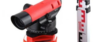
An anemometer is a device that measures the speed and direction of flow of wind, gas and other liquids.
The cup anemometer is the very first, most common and convenient type of mechanical anemometer. There are manual or induction (electronic) types of devices.
The device is widely used in:
- meteorology – used by specialists in everyday practice;
- construction – installed on cranes to control strong gusts of wind;
- industry - monitor the efficiency and performance of installations for various purposes, air conditioning, ventilation, heating systems, tunnels and mines;
- various sports - most often used in sailing, as well as in sports shooting: with a bow and crossbow, firearms and pneumatic weapons;
- agriculture - during the treatment of plants with chemicals;
- aviation - installed at airports to measure air flows and check the condition of aircraft engines.
In addition, with their help, they monitor the relevant standards in the workplace, comfortable conditions in offices, enterprises and especially factories, where a minimal deviation from the norm is fraught with serious consequences.
What device measures air speed?
All devices of this type are compact and easy to use, although they have their own subtleties.
A device for measuring air speed is called an anemometer
Instruments for measuring air speed:
- Vane anemometers
- Temperature anemometers
- Ultrasonic anemometers
- Pitot tube anemometers
- Differential pressure gauges
- Balometers
Vane anemometers are one of the simplest devices in design. The flow rate is determined by the rotation speed of the device impeller.
Temperature anemometers have a temperature sensor. When heated, it is placed in the air duct and as it cools, the air flow rate is determined.
Ultrasonic anemometers mainly measure wind speed. They work on the principle of determining the difference in sound frequency at selected control points of the air flow.
Pitot tube anemometers are equipped with a special small diameter tube. It is placed in the middle of the duct, thereby measuring the difference in total and static pressure. These are one of the most popular devices for measuring air in an air duct, but they have the disadvantage of being unable to be used in high dust concentrations.
Differential pressure gauges can measure not only speed, but also air flow. Complete with a pitot tube , this device can measure air flows up to 100 m/s.
Balometers are most effective when measuring air velocity at the outlet of ventilation grilles and diffusers. They have a bell that captures all the air coming out of the ventilation grille, thereby reducing measurement error to a minimum.
What you need to do to make a homemade anemometer
1. Using a needle, make two tiny holes in the tennis ball, one opposite the other. The easiest way to do this is to heat the tip of the needle over a fire.
2. Thread a sewing thread or fishing line through the ball, leaving about forty-five centimeters on one side. Tie it tightly and cut off any excess length.
3. Tie the other end of the fishing line to the stick and wrap it with thread until the distance between the stick and the top of the ball reaches thirty centimeters.
4. Using duct tape, attach the stick to the protractor. The thread should hang from the outside of it from a central point.
5. To measure wind speed, place the protractor in the direction of the wind. Keep it by the corners as far away from you as possible. The thread should not touch the protractor. At zero wind speed the string will hang straight down along the ninety degree mark. When the wind blows, take a reading of the degrees and then check the wind speed table.
We conducted another experiment and this time we measured the wind speed, which is constant in the region where you live. Conducting various experiments and experiences is very interesting, exciting and educational. Especially for inquisitive boys and girls like you. You can conduct other experiments in various areas and subjects. For example, it will be very interesting to find out how ants behave in their colony, what worms do underground, how you can grow your own crystal or extract DNA, how to make an electromagnet yourself, learn to walk on water, design your own telescope for observing the stars, build homemade compass and much, much more.
The weather station is built on a Picaxe microcontroller from Revolution Education Ltd and consists of two main parts: an outdoor unit that sends its data every 2 seconds using a 433 MHz transmitter. And an indoor unit that displays the received data on a 20 x 4 LCD display, as well as atmospheric pressure, which is measured locally in the indoor unit.
I tried to keep the design as simple and yet functional as possible. The device communicates with the computer via a COM port. Currently, the computer continuously builds graphs from the obtained values, and also displays the values on conventional indicators. Graphs and sensor readings are available on the built-in web server, all data will be saved, etc. You can view data for any period of time.
The weather station took several months to build, from design to completion, and overall I am very pleased with the result. I'm especially glad that I was able to build everything from scratch using regular tools. I am completely satisfied with it, but there is no limit to perfection, and this is especially true for the graphical interface. I have not made any attempt to commercialize the weather station, but if you are thinking about building a weather station for yourself, then this is a good choice.
Street sensors
Sensors are used to measure temperature, humidity, precipitation, wind direction and speed. Sensors are a combination of mechanical and electronic devices.
Temperature and relative humidity sensor
Measuring temperature is perhaps the easiest. For this, the DS18B20 sensor is used. To measure humidity, HIH-3610 was used, producing a voltage of 0.8 - 3.9V at humidity 0% to 100%
I mounted both sensors on a small PCB. The board is installed inside a homemade case that prevents exposure to rain and other external factors.
The simplified code for each of the sensors is shown below. A more accurate code that reads values down to one tenth is shown on Peter Anderson's site. Its code is used in the final version of the weather station.
The temperature sensor provides an accuracy of ±0.5 °C. The humidity sensor is accurate to ±2%, so it doesn't really matter how many decimal places are available!
An example plot from software running on a PC.
Temperature
Humidity
Calculation of humidity sensor readings
Calculations taken from the Honeywell HIH-3610 sensor documentation. The graph shows the standard dependence at 0 °C.
The voltage from the sensor is measured at the input of the ADC (B.7) of the Picaxe 18M2 microcontroller. In the code shown above, the value, which is represented as a number between 0 and 255 (i.e. 256 values), is stored in the variable b1.
Our circuit is powered by 5V, so each ADC step is: 5/256 = 0.0195V.
The graph shows the initial ADC value of 0.8 V: 0.8 / 0.0195 = 41
Taking the values from the graph, the slope of the graph (including offset) is approximately: Output Voltage / % RH or (2.65 - 0.8) / 60 = 0.0308 V in % RH (0.0306 in the documentation)
Let's calculate the number of ADC steps per 1% humidity: (V per % RH) / (ADC step) 0.0308 / 0.0195 = 1.57
% RH = ADC value - ADC offset / (ADC steps in % RH), or % RH = ADC value - 41 / 1.57
Features of air speed measurements
There are some nuances of working with different types of anemometers. As already mentioned, pitot tube anemometers cannot be used at high concentrations of solid particles, otherwise the tube will quickly become clogged and the instrument will fail. Thermal anemometers do not work in conditions of measuring high air flow velocities - over 20 m/s. When measuring speed in heated air flows (for example, in gas ducts), it is recommended to use a tube made of stainless steel rather than plastic.
What does a cup anemometer consist of?
Let's look at the structure of a hand-held cup anemometer using the MC 13 model as an example. It consists of the following parts:
- Wind receiver: blades in the form of cups, the number of which is 4. They are located in one direction, symmetrically mounted on cross-shaped wire knitting needles, which serve as a fastening for the axis, as well as protection against damage to the entire element of the device.
- The axis, which is the rotor.
- A dial containing three scales: units, hundreds and thousands.
- Screw – located at the bottom of the device for easy fastening to a support or pole.
How measurements are taken
Air velocity measurements can be made in ducts, at duct outlets, at ventilation grilles or diffusers.
When the speed measurement is carried out directly in the air duct, the measurement location should be located after the flow passes through the filters. You should find a special hole on the air duct, which is intended for control and measuring operations (such holes are often closed with a pitometer plug). You can also use a cleaning hatch.
When taking measurements with a pitot tube, it is inserted into the air duct, directed against the air flow.
"sensitive" anemometer
Technical characteristics: Measuring range from 0.5 m/s to 3.5 m/s. Accuracy 0.5 m/s. Update interval 2-5 seconds.
Cut a 3 x 2 inch (7.6 x 5.1 cm) rectangle.
Mark into three 1-inch (2.53 cm) wide rectangles.
It is very important to use a Pozidriv (PZ) slotted screw. Because in such a slot the needle does not touch the side walls. The length of the screw should be as short as possible so that the magnet is as low as possible. The photo shows a 2x6mm screw.
After tightening the screw, the “wings” are carefully separated and the impeller is given the desired shape.
In order for the magnet to hold well on the screw, you need to screw on another nut. But don't twist it.
Due to the attachment of a neodymium magnet (size 4x4x4 mm), the center of gravity of the impeller rises and it becomes unstable on the needle. To lower the center of gravity, weights need to be glued to the INNER part of the “wings” (washers for a 4 mm screw are used).
The impeller can rotate not only on an awl, but also on VERY WELL sharpened pencils or on a sewing needle attached to a pencil. The impeller spins best on a sewing needle, but this option requires great caution and is categorically NOT SUITABLE FOR CHILDREN.
About anemometers: Thermal anemometers KIMO LV 110 - LV 111 - LV 117 - buy | price 48,700 rubles
Dependence of rotation frequency on wind speed (on a mechanical pencil 0.5 mm): 1.5 Hz - 1.4 m/s 4 Hz - 2.85 m/s 6 Hz - 3.4 m/s
How to make an anemometer using arduino
The author of this homemade product once faced the question of how one can determine whether there is wind in the place where he lives. This question arose because he wanted to install a wind turbine to generate electricity. Using this ingenious device, you can take measurements of how often the wind blows, at what average speed it blows, and so on. The basis for collecting and processing information is the Arduino board.
Materials and tools for making an anemometer: - a piece of square pipe; - Bulgarian; — welding; — bearing; - scan; - nails; - dye; — LED-phototransistor sensor (can be removed from the printer); — Arduino circuit; - minimum set of tools.
About anemometers: Multifunctional anemometer MEGEON 11990 - Order with delivery!
Manufacturing process:
Step one. Making an anemometer sensor
To make a sensor, you need to take a piece of a square pipe and then cut a window in it, through which the filling will then be installed. A metal plate needs to be welded inside this pipe; it will act as a bearing holder. Then another plate is welded to fix the lower bearing.
The author decided to make the top in the form of a pitched roof. To do this, take four triangles, first tack them by welding, and then boil them well.
Next, the workpiece is clamped in a vice and the diameter of the drill is 0.5 mm less than the diameter of the bearing in the bottom cover and a hole is drilled in the middle. Both are needed for bearings. To ensure that the bearings fit into place with tension, the size of the holes is adjusted using a reamer. Once the bearings were installed, a 100-gauge nail was inserted into them. In the middle of the window, a plastic washer with four slots is placed on it. A thread was cut from the bottom of the nail and then the impeller was screwed onto this axis.
Step two. Impeller manufacturing process
To make an impeller you need to take a nut and weld three nails to it with a 2mm electrode. The ends of the nails are trimmed and threaded. Then the halves of the ball are put on the ends.
A hexagonal stainless steel rod was welded to the body as a holder. And to prevent the body from rusting, it was covered with white enamel.
In order for the sensor to read information, you need a washer with slots. The author took it out of an old ball-point computer mouse. When the slot passes in front of the LED phototransistor sensor, it sends a signal to the electronics.
As for the impeller blades, they were first made from tennis balls. With this size of blades, the impeller starts in winds of 5 m/s. To make the impeller more sensitive, balls with a diameter of 55 mm were purchased; in this case, the impeller begins to rotate already at m/s. In this case, measurements are carried out up to 22 m/s.
Step three. Electronic part
As an electronic circuit, the author first used a homemade LUT circuit with the addition of a green maxi from China. But the system could not show wind speed in meters/second. It only displayed the number of revolutions.
At the moment the circuit is being assembled on Arduino. The operating principle of the author's anemometer is exactly the same as that of a computer mouse. Now you just need to connect the two circuits.
It was decided to transmit pulses from the phototransistor to Arduino, and the circuit began to perceive such signals as button presses. To get the wind speed, you just need to count how many button presses there are during a certain time, say, per second.
That's all, now the anemometer can be considered ready. If necessary, you can add a function to the code that would count how long the wind blew at a certain speed. This homemade product will be an excellent addition for those who are planning to install a windmill or closely monitor the weather.
anemometr.rar [9.54 Kb] (downloads: 1118)
Table for determining wind speed by external signs
| wind pattern | wind speed m/sec | signs |
| very light | 0-1 | air movement is imperceptible |
| 1-3 | air movement is barely noticeable, leaves rustle | |
| easy | 4-5 | the branches sway slightly, the smoke floats in the air, maintaining the outline of the clouds |
| moderate | 6-7 | branches bend, the wind “licks” the smoke from the chimney and mixes it into a homogeneous mass, dust rises |
| fresh | 8-9 | the treetops rustle and sway |
| very fresh | 10-11 | thin tree trunks bend, the wind howls in the pipes |
| strong | 12-14 | leaves are torn off, waves are formed on standing water with overturning crests |
| cutting | 15-16 | thin branches break, movement against the wind is difficult |
| storm | 17-19 | thick branches break, tearing off roof coverings |
| strong storm | 20-23 | thin ropes break |
When going to work in the fall and or winter, it is not always clear at night what the weather is like outside, in particular what the wind is like. I think in a strong wind it is useful to dress the children warmly, and not to make a mistake yourself. In case of bad weather, it is also interesting to know the speed of the wind raging outside the window.
Remembering the saying “prepare a sleigh in the summer,” I decided to build an anemometer with my own hands in the summer. There was experience in creating homemade anemometers (wind speed meters), but the designs were created a long time ago on an old electronic base in the 80s of the last century and time has not been kind to them.
While disposing of another VCR, I decided to leave a trace of it on Earth. All VCRs have a rotating head unit. This is a precision assembly of high accuracy and reliability - the heart of every VCR. The unit is made of stainless metal with a rotating head axis on sealed bearings.


