Operation of the units is possible in conjunction with expansion switches.
As for the negative resistance indicator, its value in the circuit can correspond to a value of 55 Ohms.
These devices are connected to the generator based on the type of electrical network into which the switch will be connected. connection of machines
In such modifications, copper conductors. Another feature: low output voltage, mainly V. Sometimes such switches complement counters.
Article Video In some cities, as well as in suburban areas, there is a problem with unstable electricity supply. A power supply rated B is used as an element connecting all available parts. At the network input, protection is installed in the form of a circuit breaker located in the metering panel.
How to divide electrical wiring into groups. DIY electrical wiring
Changeover switches for generators: connection diagrams
To be able to switch electricity to the necessary devices, special devices are installed - changeover switches.
An important part of their design are blockers. There are different versions of such devices on the market; they are distinguished primarily by their performance characteristics. It must be taken into account that devices are connected using different circuits depending on the types of electrical networks. Their operating parameters can be adjusted using control units. Also, similar switches are used in industrial production, where they serve backup generators. To understand especially the connection diagrams, you need to familiarize yourself with the types of devices that are presented in our country.
Installation recommendations
To use the device safely and correctly, the following recommendations must be observed:
- The device must be installed indoors;
- the device must be protected from moisture, as well as from bad climatic conditions;
- the required operating environment temperature for the device ranges from -40 to +55 degrees;
- if the upper part of the contact knife burns, it is necessary to clean it with a file;
- It is necessary that the device is securely and firmly installed.
If the changeover switch is installed outdoors, then it is necessary to ensure protection from environmental influences. It is also necessary to ensure that the device operates within the permissible temperature range - that is, if outdoors, then it is necessary to ensure heating of the cabinet where this switch is installed. Installation, maintenance and repair of the device should only be carried out by a specialist, and only when the power supply is completely disconnected.
Finally, we recommend watching a video that explains in more detail how to connect a changeover switch to the network:
It will be useful to read:
- How to install a diesel generator
- How to connect a three-phase voltage stabilizer
- Connecting the generator to the home network
- What is a load switch used for?
A changeover switch is a special device designed to switch electricity to the necessary devices, operating using a manual drive. Manufacturers offer a wide range of such devices, differing in various technical characteristics.
It is important to remember that there are various options for connecting changeover switches - the choice depends on the characteristics of the electrical network. The most popular switch type switches are in residential buildings. To change the operating characteristics of such devices, control units are used.
In addition, these devices have found application in industry when operating backup generators. When choosing a changeover switch for a generator, you need to take into account its configuration and the specifics of the existing grounding.
The quality of operation of the device is ensured by equipping it with a grounding electrode. Its marking indicates the degree of protection. It is optimal if it is IP30.
Single pole switches
In many cases, devices with only one module are used .
In such modifications, copper conductors. It is important to know that they should be used to service generators whose operating frequency range is not higher than 20 Hz. There are also certain disadvantages that are taken into account when choosing. An important nuance: the maximum load during use should not exceed 200 A. Therefore, they are not installed in residential buildings where there is significant electricity consumption. Another feature: low output voltage, mostly 200 V.
Selecting ATS
The table below will help you decide on the type of ATS.
Table 1
| ATS type | Device Features | Action |
| Single acting | Two sections. One working and one backup | Connects a backup line in case of power failure on the main one |
| Double acting | Sections are equivalent | You can connect any line, regardless of voltage availability |
| With restoration | Monitors the presence of voltage at the main input after switching to backup power | When voltage appears on the main line, it transfers the circuit (with a slight delay) to its original state |
| No recovery | Switches sections after voltage loss at the main input | Operator intervention is required to switch to main mode |
Double pole switches
It is the two-way changeover switch that is installed in multi-storey buildings. It can be used to service units connected to both single-phase and two-phase systems. Average negative resistance values are at 60 ohms.
The output voltage may not be the same, depending on the modification of the device. Devices from the PP20 series with open capacitors are often used. When connecting them, you cannot do without power supplies with an operating voltage of 300 V.
Connection diagrams
It is worth understanding that the connection procedure may differ and depends primarily on the type of electrical networks.
Single-phase network
Only two-pole devices . It is also necessary to have a power supply with an operating voltage of 300 V.
- In such modifications, the negative resistance will reach 50 Ohms. Sometimes such switches complement counters. But switches are rare.
- When choosing jumpers that provide contacts, keep in mind that you should buy only copper ones.
- Before installing the device in a residential building, you should make sure that there are electrical panels of the KK220 series or others. Due to possible discrepancies in performance characteristics, reversing units are not used for single-phase circuits.
Two-phase network
In two-phase circuits, the connecting element is a 200 V power supply. Remember that only expansion type switches are used for these devices. Then the switches can be used in a single-phase network, regardless of the number of modules used. The maximum voltage is 300 V. Most often, products of the PP30 series are chosen.
- In accordance with the design features, they are equipped with only two modules, which means that the output voltage will correspond to 350 V.
- Blockers may not be the same. Before use in residential buildings, you should make sure that there are electrical panels there. This is a must. Control units are traditionally composed of thyristors.
- The negative resistance limit is 40 ohms. Contact systems are only applicable to closed type models. Control of power fluctuations is provided by feed-through capacitors.
- The reversing unit maintains the required current frequency. If two different models are used, they must be combined with the controller. This will minimize the negative impact of nonlinear distortions that occur from time to time in the network.
Three-phase network
Power supplies for three-phase networks must have an operating voltage of 400 V. It is worth noting that only pulse transformers .
- The connection procedure itself is performed using the inverting output. The output current is supplied through special devices, the role of which will be played by pass capacitors. It makes sense to use two-module switches.
- Single-module modifications are also offered on the markets. Their main feature is that the minimum threshold voltage limit is at 350 V, the negative resistance is 55 Ohms. The design of the switch must include a blocker.
- Residential buildings must have special electrical panels of the KK22 series. In such designs, control units can be composed not only of thyristors, but also of dinistors.
Changeover switch for generator
For generators, you should choose only changeover-type, single-module switches . The blocker must have a classic contact system. As a rule, reversible units contain controllers. For this reason, models with resonators are not recommended.
In such cases, the threshold frequency will be at a fairly high level. The switches here may not be the same size. It is worth paying attention to the number of pass capacitors that are used.
Before starting installation, you must carefully study the grounding system. The device can only be effective with a special grounding electrode. The marking of electrodes must indicate the degree of protection and its system. Domestic stores mainly offer IP30 electrodes with fairly strong insulation, which will provide the system with a large number of operating cycles.
When choosing changeover switches for a generator, you must take into account that they are used in a single-phase network
. They have two pass-through capacitors .
But on sale you can find not only two-module, but also three-module products. The connection diagram may also provide for connecting a meter. The installation itself is carried out using copper jumpers. Switches should only be expansion switches. Any electrical panels are suitable for the devices. The threshold voltage is 350 V. Average load parameters can reach 30 A.
Switches for generators are an effective solution that has a number of advantages. They are convenient to maintain, you can control the operating parameters of electrical networks, avoiding emergency situations that can damage the connected equipment.
Source
Briefly about the main thing
Connecting a private house to a 3-phase network makes it possible to reduce the load on a phase, use conductors of a smaller cross-section and connect both 1-phase and 3-phase equipment. The electrical panel must provide protection not only for electrical appliances and conductors, but also for the people in the house. The main feature of assembling a 3-phase electrical panel for 15 kilowatts is to correctly distribute the load and prevent phase imbalance.
The 3-phase electrical panel should include the following devices:
- Electrical cabinet
- Counter.
- Introductory machine.
- RCD.
- Circuit breakers for groups.
- Voltage relay.
- Current and voltage meters.
The panel can be assembled in several variations - only on automatic machines, with one RCD, with the load distributed over 2 RCDs, with an RCD in each phase and the number of RCDs more than 3 for a powerful device or group. Each scheme has its own pros, cons and application features. The shield must be installed in accordance with special rules and proper load distribution across phases.
Ratings 0
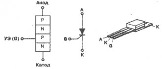
What is a rocker switch
Reversing changeover switch
The purpose of a changeover switch is to transfer voltage between two lines or connect several networks. Using a switch, you can eliminate current leaks during accidents and quickly switch to the entire line. The device is switched using a lever on the front panel, which is moved to 1-2 positions.
The equipment is installed in the switchboard room or near the input panel.
Device specifics
A toggle-type switch is similar to a two-position switch in its operating principle, but is distinguished by increased power and a smooth blade drive. The second difference is the switching process with a line break and operation in three positions:
- apartment/home network;
- shutdown;
- power supply from the generator.
Rules for distributing the load of machines
When distributing the load across 3 phases, you must adhere to the following set of rules:
- Power supply for lamps and sockets must come from different circuit breakers.
- Equipment in rooms with damp air (bathroom, kitchen, shower, bath) must be connected via its own switch.
- The power supply to outbuildings, street lights and sockets must be connected through a separate circuit breaker.
- The electric drive of gates, gates, and security lighting must be powered separately.
- The water heating and heating system must be connected through its own RCD.
Pros and cons of using switches
The advantage of a changeover switch is its low cost
An electric switch is the simplest device, which is characterized by advantages and disadvantages. The advantages of operation include:
- Visibility. The device can be visually inspected for damage. The position of the knives is clearly visible.
- Simple design. A small number of components simplifies maintenance and repair of the device.
- High switching current. The switch switches current of 500, 630 or 1000 Amps.
- Low cost. You can purchase a switch for installation in a private house or apartment.
Despite the positive characteristics, the machine has several disadvantages:
- Open type design. All elements are in plain sight; if touched carelessly, there is a risk of electric shock.
- Irregular switching speed. If the knives are moved slowly, a high-temperature arc is formed, which burns out the internal components of the device.
- Possibility of short circuit when a high-temperature arc occurs.
- The occurrence of current surges when switching before the load is turned off.
To protect open parts, the changeover relay is hidden in a special box.
Changeover switches
Changeover switch 4-pole 63A AvaTar
An electric switch ensures disconnection of the network from one energy source and connection to another. The presence of a midpoint explains the name “cross over”. The devices are produced with arc extinguishers that provide switching when the voltage is connected. Models without arc extinguishing mechanisms are switched when the load is turned off. The switch operates only in manual mode - switching is carried out using an isolated control lever.
The design of the device is presented:
- sealed housing;
- movable blade contacts with two working positions and one intermediate;
- arc extinguishing chamber, but there are switches without it;
- terminals for connecting to the network.
Connection to one load line is carried out according to the principle:
- The main power supply is connected to contact No. 1.
- A diesel or electric generator is connected to pin No. 2.
If input into a building with three-phase voltage is required, a three-phase switch with 4 poles is used. The device is connected like this:
- You need to enter the power supply through 4 terminals.
- A generator is connected to 4 terminals.
- The load is connected to 4 terminals.
Zero is connected to one terminal out of four, and phase is connected to three.
What does a pass-through switch look like and work?
If we talk about the front side, the only difference is: a barely noticeable arrow on the up and down key.
What does a single-key pass-through switch look like? You see there are double arrows
If we talk about the electrical circuit, everything is also simple: in ordinary switches there are only two contacts, in pass-through switches (also called changeover contacts) there are three contacts, two of which are common. There are always two or more such devices in the circuit, and they are switched using these common wires.
The difference is in the number of contacts
The operating principle is simple. By changing the position of the key, the input is connected to one of the outputs. That is, these devices have only two working positions:
- input connected to output 1;
- input is connected to output 2.
There are no other intermediate provisions. Thanks to this, everything works. Because the contact switches from one position to another, electricians believe it is more correct to call them “switches.” So a pass-through switch is also this device.
In order not to rely on the presence or absence of arrows on the keys, you need to inspect the contact part. Branded products should have a diagram on them that allows you to understand what type of equipment you have in your hands. It is definitely found on products from Lezard, Legrand, and Viko. They are often absent on Chinese copies.
This is what the changeover switch looks like from the rear
If there is no such diagram, look at the terminals (copper contacts in the holes): there should be three of them. But not always on inexpensive copies the terminal that stands alone is the input. They are often confused. To find where the common contact is located, you need to ring the contacts with each other at different key positions. This must be done, otherwise nothing will work, and the device itself may burn out.
You will need a tester or multimeter. If you have a multimeter, set it to sound mode - it beeps when there is contact. If you have a pointer tester, ring for a short circuit. Place the probe on one of the contacts, find which of the two it rings with (the device beeps or the arrow shows a short circuit - it deviates to the right all the way). Without changing the position of the probes, change the position of the key. If the short circuit is missing, one of these two is common. Now all that remains is to check which one. Without switching the key, move one of the probes to another contact. If there is a short circuit, then the contact from which the probe was not moved is the common one (this is the input).
It may become clearer if you watch a video on how to find the input (common contact) for a pass-through switch.
Features of using a three-position switch
Three-position changeover switch
A three-pole switch is suitable for connecting backup power to a home line. It is used only after the load has been disconnected. The generator will need to be activated and set to working position. Then you need to connect your home network to it. When carrying out repair work, the switch will be used as a disconnector.
Device installation
Changeover electrical equipment is installed in the switchboard. Models with a plastic case are suitable for indoor installation, and metal ones for external installation. Inside the boxes there is a special DIN rail for switches. Installation of devices is carried out as follows:
- Models that switch off under load are installed vertically.
- The type of tires and wires is selected. Their cross section must correspond to the current rating of the switches.
- Buses and wires are connected to fixed contacts.
- The elements are tightly clamped with terminals to ensure reliable contacts and eliminate the possibility of overheating.
To ensure that the switch works without failures, installation is carried out indoors. The device needs to be protected from moisture, and then checked for tight fit on the DIN rail.
Switching order
Before connecting, you must stop the input machine
Three-position or package devices are produced without a disconnector. They connect like this:
- Stopping the introductory machine.
- Installing the device handle on the generator line.
- Switching off the load breaker.
- Connecting the switch cable to the generator socket.
- Start the generator, wait for warm-up (2 minutes).
- Supplying power to the switch.
- Turning on the load breakers.
Machines are installed on each of the inputs.
Basic connection diagrams
The connection diagram of the changeover switch is determined by the type of electrical network.
Single-phase network
Only two-pole modifications with power supplies with an operating voltage of 300 V are connected to this line. The connection is made with a negative resistance rating of 50 Ohms. The devices are placed on copper jumpers. Installation in a residential building is carried out in electrical panels of type KK220.
Reversible units are not suitable for single-phase networks.
Two-phase line
For a two-phase network, only expansion switches are suitable. To them you will need to add a connecting node - 220 V power supplies. The maximum voltage of modular devices is 300 V, but the presence of two modules allows an output voltage limit of 350 V.
The process of connecting switches has several nuances:
- the blocker is installed in the electrical panel together with the thyristor unit;
- the negative resistance rating is 40 ohms;
- contact systems are used only in closed switches;
- If you have two reversing units from different manufacturers, you will need a controller.
The controller is used to prevent non-linear distortion of the network.
Three-phase power supply
Connection diagram of a switch to a three-phase network
The switch is combined with a power supply with an operating voltage rating of 400 V and pulse transformers. The device can be entered through the inverting output. Output currents will be supplied through pass capacitors.
For a three-phase network, it is allowed to use two-module and single-module devices. The latter must have a threshold voltage of 350 V and a negative resistance of 55 Ohms.
For three phases, only a switch with a blocker is suitable.
Connecting the generator to a changeover switch
Connecting the generator via an ABB switch
To organize the coupling, you will need two modular contacts or an electrical switch for 7 contacts. A pair of them should be normally closed, and a pair should be normally open. The connection is made like this:
- It is required to enter the extreme contact of the switch to enter the line and cable of the station.
- The middle contact is brought to the consumer.
- The switch is placed in its original position - connected to the main network.
- During the switching process, power is supplied from the generator.
- The switch is installed in the control panel.
- To warm up the system and supply power after activating the generator, a time relay is installed.
- The backup contactor is energized through the main input communicator via a normally closed contact.
Switching processes are implemented by the user. It sets the switch to neutral mode in case of voltage drop. When it resumes, the first contact is activated, opening the power circuit of the second input.
Three-phase switches
Three-phase power switches are widely used in control circuits for powerful asynchronous electric motors; their purpose is to switch the winding from star to delta. This implementation allows you to significantly reduce the starting current. The figure shows a diagram of such a connection.
Switching diagram of electric motor windings
Symbols on the diagram:
- A, B, C – power phases;
- C1, C2, C3, C4, C5, C6 – outputs of the electric motor windings;
- SA – three-pole power switch.
The electric motor starts when its windings are connected in a star; when entering normal mode, it switches to a delta.
Self-assembly of a changeover switch for a generator
Making a switch with your own hands is done step by step:
- Selection of machines based on the number of switching circuits. For two-phase, 2 bipolar or 4 single-pole models are installed.
- Installation of automatic machines in the switchboard. One is placed in a standard position, the second is turned over.
- Switching nodes with wires.
- Installing a steel retainer in the pusher (there are gaps for it in the machine). The bar will allow you to switch all the machines at the same time.
- Checking the quality of the system - you should hear a click.
You cannot make a three-position switch yourself - you will only end up with a two-position device.