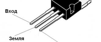
Hello, dear readers of the site. At the beginning of their studies in radio electronics, beginning radio amateurs, and not only radio amateurs, have a lot of questions related to continuity or determination of transformer windings. This is good if the transformer has only two windings. And if there are several of them, and each winding also has several outputs. Here you just shout guard. In this article I will tell you how you can determine the windings of a transformer by visual inspection and using a multimeter.
As you know, transformers are designed to transform
alternating voltage of one magnitude into alternating voltage of another magnitude.
The most common transformer has one primary
and one
secondary
winding. The supply voltage is supplied to the primary winding, and the load is connected to the secondary winding. In practice, most transformers can have several windings, which makes it difficult to determine them.
How to test a transformer with a multimeter
The main use of a transformer is to change the characteristics of electricity and voltage. Despite the fact that this device makes very difficult transformations, its design is extremely simple. It consists of a core, a number of coils of copper wire are wound around it. Among them, one is input (or in other words primary), the rest of the coils are called secondary or output.
Initially, the current flows to the input coil, on which a voltage arises as a result of the induction of a magnetic field. The final of the secondary coils creates an alternating type current, equal in its characteristics to the current in the primary coil. If there are different numbers of turns wound on the input and output windings, then accordingly the current characteristics will be different. As they say, everything ingenious is simple. But this device quite often fails, and its defects are usually not invisible to the naked eye. It is because of this that the question increasingly comes up: how to test a converter with a multimeter or other measuring device?
It should be noted that various testers, including a multimeter, will be needed even if you have a transformer with parameters that are not marked and unfamiliar to you. It will also be possible to find them out with a multimeter.
Before starting work, you first need to get your bearings with the coils. It will be necessary to remove all the ends of the windings outwards, move them apart and check with a multimeter, with this we will find the beginning and end of each of the coils. We number the input and output of each coil.
The simplest case is when you have only four endings, so you get two for each winding. However, you often come across devices that have more than four ends. It may be that some of them will not ring through, but this does not mean that a break has occurred somewhere. Most likely, this is a shielding winding, which is usually located between the input and output windings and is usually connected to ground.
We connect an unknown transformer to the network.
Nikolay Petrushov
How to deal with the windings of a transformer, how to properly connect it to the network and not “burn it” and how to determine the maximum currents of the secondary windings??? Many beginning radio amateurs ask themselves these and similar questions. In this article I will try to answer such questions and, using the example of several transformers (photo at the beginning of the article), to understand each of them.. I hope this article will be useful to many radio amateurs.
First, remember the general features for armored transformers
— The mains winding, as a rule, is wound first (closest to the core) and has the highest active resistance (unless it is a step-up transformer, or a transformer with anode windings).
— The network winding may have taps, or consist, for example, of two parts with taps.
— The serial connection of windings (parts of windings) for armored transformers is carried out as usual, beginning to end or terminals 2 and 3 (if, for example, there are two windings with terminals 1-2 and 3-4).
- Parallel connection of windings (only for windings with the same number of turns), the beginning is made as usual with the beginning of one winding, and the end with the end of another winding (n-n and k-k, or pins 1-3 and 2-4 - if for example there are identical windings with pins 1-2 and 3-4).
General rules for connecting secondary windings for all types of transformers.
To obtain different output voltages and load currents of windings for personal needs, different from those available on the transformer, can be obtained by various connections of the existing windings to each other. Let's consider all possible options. — Windings can be connected in series, including windings wound with wires of different diameters, then the output voltage of such a winding will be equal to the sum of the voltages of the connected windings (Utotal = U1 + U2... + Un). The load current of such a winding will be equal to the smallest load current of the available windings. For example: there are two windings with voltages of 6 and 12 volts and load currents of 4 and 2 amperes - as a result, we get a common winding with a voltage of 18 volts and a load current of 2 amperes. — Windings can be connected in parallel only if they contain the same number of turns
, including those wound with wires of different diameters.
The correct connection is checked like this. We connect two wires from the windings together and measure the voltage on the remaining two. If the voltage is doubled, then the connection was not made correctly, in this case we change the ends of any of the windings. If the voltage at the remaining ends is zero or so (a difference of more than half a volt is not desirable, the windings in this case will heat up at XX), feel free to connect the remaining ends together. The total voltage of such a winding does not change, and the load current will be equal to the sum of the load currents of all windings connected in parallel. (Itotal = I1 + I2… + In) . For example: there are three windings with an output voltage of 24 volts and load currents of 1 ampere each. As a result, we get a winding with a voltage of 24 volts and a load current of 3 amperes. — The windings can be connected in parallel-series (for features for parallel connection, see the paragraph above). The total voltage and current will be the same as in a series connection. For example: we have two series and three parallel connected windings (examples described above). We connect these two component windings in series. As a result, we get a common winding with a voltage of 42 volts (18+24) and a load current along the smallest winding, that is, 2 amperes. — The windings can be connected back-to-back, including those wound with wires of different diameters (also parallel and series-connected windings). The total voltage of such a winding will be equal to the difference in voltages of oppositely connected windings, the total current will be equal to the smallest winding load current. This connection is used when it is necessary to reduce the output voltage of the existing winding. Also, in order to reduce the output voltage of any winding, you can wind an additional winding on top of all the windings with a wire, preferably no smaller in diameter than the winding whose voltage needs to be reduced, so that the load current does not decrease. The winding can be wound without even disassembling the transformer, if there is a gap between the windings and the core, and it can be connected opposite the desired winding. For example: we have two windings on a transformer, one is 24 volts 3 amperes, the second is 18 volts 2 amperes. We turn them on oppositely and as a result we get a winding with an output voltage of 6 volts (24-18) and a load current of 2 amperes. But this is purely theoretical, in practice the efficiency of such a connection will be lower than if the transformer had one secondary winding. The fact is that the current flowing through the windings creates an EMF in the windings, and in a larger winding the voltage decreases in relation to the voltage XX, and at less - increases, and the greater the current flowing through the windings, the greater this effect.
As a result, the total rated voltage (at rated current) will be lower. Let's start with a small transformer, adhering to the features described above (left in the photo). We examine it carefully. All its terminals are numbered and the wires fit to the following terminals; 1, 2, 4, 6, 8, 9, 10, 12, 13, 22, 23, and 27. Next, you need to test all the terminals with an ohmmeter to determine the number of windings and draw a diagram of the transformer. The following picture emerges. Pins 1 and 2 - the resistance between them is 2.3 Ohms, 2 and 4 - between them is 2.4 Ohms, between 1 and 4 - 4.7 Ohms (one winding with a middle pin). Further 8 and 10 - resistance 100.5 Ohms (another winding). Pins 12 and 13 - 26 Ohm (another winding). Pins 22 and 23 - 1.5 Ohm (last winding). Pins 6, 9 and 27 do not communicate with other pins or with each other - these are most likely screen windings between the network and other windings. These terminals in the finished design are interconnected and attached to the housing (common wire). Let's carefully inspect the transformer again. The network winding, as we know, is wound first, although there are exceptions.
It's hard to see in the photo, so I'll duplicate it. A wire coming from the core itself is soldered to pin 8 (that is, it is closest to the core), then a wire goes to pin 10 - that is, winding 8-10 is wound first (and has the highest active resistance) and is most likely network. Now, based on the data received from the dialing, you can draw a diagram of the transformer.
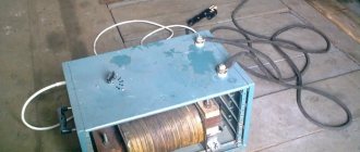
All that remains is to try to connect the supposed primary winding of the transformer to a 220 volt network and check the no-load current of the transformer. To do this, we assemble the following chain.
In series with the intended primary winding of the transformer (for us these are pins 8-10), we connect an ordinary incandescent lamp with a power of 40-65 watts (for more powerful transformers 75-100 watts). In this case, the lamp will play the role of a kind of fuse (current limiter), and will protect the transformer winding from failure when connected to a 220 volt network, if we have chosen the wrong winding or the winding is not designed for a voltage of 220 volts. The maximum current flowing in this case through the winding (with a lamp power of 40 watts) will not exceed 180 milliamps. This will protect you and the transformer being tested from possible troubles.
-And in general, make it a rule that if you are not sure about the correct choice of the network winding, its switching, or the installed winding jumpers, then always make the first connection to the network with an incandescent lamp connected in series.
Being careful, we connect the assembled circuit to a 220 volt network (I have a slightly higher network voltage, or rather 230 volts). What do we see? The incandescent lamp does not light. This means that the network winding has been selected correctly and further connection of the transformer can be made without a lamp. We connect the transformer without a lamp and measure the no-load current of the transformer.
The no-load current (OC) of the transformer is measured as follows; a similar circuit is assembled that we assembled with a lamp (I won’t draw it anymore), only instead of the lamp an ammeter is turned on, which is designed to measure alternating current (carefully inspect your device for the presence of such a mode). The ammeter is first set to the maximum measurement limit, then, if there is a lot of it, the ammeter can be transferred to a lower measurement limit. Being careful, we connect to a 220 volt network, preferably through an isolation transformer. If the transformer is powerful, then at the moment the transformer is connected to the network, it is better to short-circuit either with an additional switch, or simply short-circuit with each other, since the starting current of the primary winding of the transformer exceeds the no-load current by 100-150 times and the ammeter may fail. After the transformer is connected to the network, the ammeter probes are disconnected and the current is measured.
The no-load current of the transformer should ideally be 3-8% of the rated current of the transformer. It is considered normal that the current is 5-10% of the rated value. That is, if a transformer with a calculated rated power of 100 watts, the current consumption by its primary winding is 0.45 A, then the XX current should ideally be 22.5 mA (5% of the nominal) and it is desirable that it does not exceed 45 mA (10 % of face value).
As you can see, the no-load current is a little more than 28 milliamps, which is quite acceptable (well, maybe a little too high), since this transformer looks like it has a power of 40-50 watts. We measure the open-circuit voltage of the secondary windings. It turns out at terminals 1-2-4 17.4 + 17.4 volts, terminals 12-13 = 27.4 volts, terminals 22-23 = 6.8 volts (this is at a network voltage of 230 volts). Next we need to determine the capabilities of the windings and their load currents. How it's done? If it is possible and the length of the winding wires suitable for the contacts allows, then it is better to measure the diameters of the wires (roughly up to 0.1 mm - with a caliper and accurately with a micrometer), and according to the table HERE, with an average current density of 3-4 A/mm.sq. — we find the currents that the windings are capable of producing. If it is not possible to measure the diameters of the wires, then proceed as follows. We load each of the windings in turn with an active load, which can be anything, for example, incandescent lamps of various power and voltage (an incandescent lamp with a power of 40 watts at a voltage of 220 volts has an active resistance of 90-100 Ohms in a cold state, a lamp with a power of 150 watts - 30 Ohm), resistance wires (resistors), nichrome spirals from electric stoves, rheostats, etc. We load until the voltage on the winding decreases by 10% relative to the no-load voltage. Then we measure the load current.
This current will be the maximum current that the winding is capable of delivering for a long time without overheating.
The voltage drop is conventionally accepted to be up to 10% for a constant (static) load in order to prevent the transformer from overheating. You may well take 15%, or even 20%, depending on the nature of the load. All these calculations are approximate. If the load is constant (incandescent lamps, for example, a charger), then a smaller value is taken, if the load is pulsed (dynamic), for example ULF (except for mode “A”), then a higher value can be taken, up to 15-20%.
I take the static load into account, and I succeeded; winding 1-2-4 load current (with a decrease in winding voltage by 10% relative to the no-load voltage) - 0.85 amperes (power about 27 watts), winding 12-13 (pictured above) load current 0.19-0, 2 amperes (5 watts) and winding 22-23 - 0.5 amperes (3.25 watts). The rated power of the transformer is about 36 watts (rounded to 40). Yes, I also want to talk about the resistance of the primary winding. For low-power transformers it can be tens or even hundreds of Ohms, and for high-power transformers it can be a few Ohms. Very often these questions are asked on the forum; “I measured the resistance of the primary winding of the TC250 with a multimeter, and it turned out to be 5 Ohms. Isn’t it too small for a 220 volt network, I’m afraid to plug it into the network. Tell me, is it normal?” Since all multimeters measure resistance to direct current (active resistance), there is no need to worry, because for alternating current with a frequency of 50 hertz, this winding will have a completely different resistance (inductive), which will depend on the inductance of the winding and the frequency of the alternating current. If you have something to measure inductance with, then you can calculate the winding resistance to alternating current (inductive reactance) yourself. For example; The inductance of the primary winding during the measurement was 6 H, go here and enter this data (inductance 6 H, mains frequency 50 Hz), look - it turned out to be 1884.959 (rounded up to 1885), this will be the inductive reactance of this winding for a frequency of 50 Hz . From here you can calculate the no-load current of this winding for a voltage of 220 volts - 220/1885 = 0.116 A (116 milliamps), yes, you can also add an active resistance of 5 Ohms here, that is, it will be 1890. Naturally, for a frequency of 400 Hz there will be a completely different resistance of this winding.
Other transformers are checked in the same way. The photo of the second transformer shows that the terminals are soldered to contact petals 1, 3, 4, 6, 7, 8, 10, 11, 12. After dialing, it becomes clear that the transformer has 4 windings. The first is on pins 1 and 6 (24 Ohm), the second is 3-4 (83 Ohm), the third is 7-8 (11.5 Ohm), the fourth is 10-11-12 with a tap from the middle (0.1+0.1 Ohm) .
Moreover, it is clearly visible that windings 1 and 6 are wound first (white leads), then comes winding 3-4 (black leads). 24 Ohms of active resistance of the primary winding is quite enough. For more powerful transformers, the active resistance of the winding reaches several Ohms. The second winding is 3-4 (83 Ohms), possibly boosting. Here you can measure the diameters of the wires of all windings, except for winding 3-4, the terminals of which are made of black, stranded, mounting wire.
Next we connect the transformer through an incandescent lamp. The lamp does not light up, the transformer looks like it has a power of 100-120, we measure the no-load current, it turns out 53 milliamps, which is quite acceptable. We measure the open-circuit voltage of the windings. It turns out 3-4 - 233 volts, 7-8 - 79.5 volts, and winding 10-11-12 at 3.4 volts (6.8 with the middle terminal). We load winding 3-4 until the voltage drops by 10% of the no-load voltage, and measure the current flowing through the load.
The maximum load current of this winding, as can be seen from the photograph, is 0.24 amperes. The currents of other windings are determined from the current density table, based on the diameter of the winding wire. Winding 7-8 is wound with 0.4 wire and filament with 1.08-1.1 wire. Accordingly, the currents are 0.4-0.5 and 3.5-4.0 amperes. The rated power of the transformer is about 100 watts.
There is one more transformer left. It has a contact strip with 14 contacts, the top 1, 3, 5, 7, 9, 11, 13 and bottom are even, respectively. It could switch to different mains voltages (127,220,237); it is quite possible that the primary winding has several taps, or consists of two half-windings with taps. We call, and we get the following picture: Pins 1-2 = 2.5 Ohm; 2-3 = 15.5 Ohm (this is one winding with a tap); 4-5 = 16.4 ohms; 5-6 = 2.7 Ohm (another winding with tap); 7-8 = 1.4 Ohm (3rd winding); 9-10 = 1.5 Ohm (4th winding); 11-12 = 5 Ohm (5th winding) and 13-14 (6th winding). We connect to pins 1 and 3 a network with an incandescent lamp connected in series.
The lamp burns at half intensity. We measure the voltage at the terminals of the transformer, it is 131 volts. This means they didn’t guess right and the primary winding here consists of two parts, and the connected part at a voltage of 131 volts begins to enter saturation (the no-load current increases) and therefore the lamp filament becomes hot. We connect pins 3 and 4 with a jumper, that is, two windings in series and connect the network (with a lamp) to pins 1 and 6. Hurray, the lamp is not lit. We measure the no-load current.
The no-load current is 34.5 milliamps. Here, most likely (since part of winding 2-3, and part of the second winding 4-5 have greater resistance, then these parts are designed for 110 volts, and parts of windings 1-2 and 5-6 are 17 volts each, that is, the total for one part 1278 volts) 220 volts was connected to pins 2 and 5 with a jumper on pins 3 and 4 or vice versa. But you can leave it the way we connected it, that is, all parts of the windings in series. This is only better for the transformer. That's it, the network has been found, further actions are similar to those described above.
A little more about core transformers. For example, there is one like this (photo above). What are their common features?
— Rod transformers usually have two symmetrical coils, and the mains winding is divided into two coils, that is, 110 (127) volt turns are wound on one coil, and on the other. The numbering of the terminals of one coil is similar to the other; the terminal numbers on the other coil are marked (or conventionally marked) with a stroke, i.e. 1′, 2′, etc.
— The mains winding, as a rule, is wound first (closest to the core).
— The network winding may have taps, or consist of two parts (for example, one winding - terminals 1-2-3; or two parts - terminals 1-2 and 3-4).
-In a rod transformer, the magnetic flux moves along the core (in a “circle, ellipse”), and the direction of the magnetic flux of one rod will be opposite to the other, therefore, to connect the two halves of the windings in series, contacts of the same name or beginning to beginning (end to end) are connected on different coils ), i.e. 1 and 1′, the network is served on 2-2′, or 2 and 2′, the network is then served on 1 and 1′.
- For a serial connection of windings consisting of two parts on one coil - the windings are connected as usual, beginning to end or end to beginning, (n-k or k-n), that is, pin 2 and 3 (if, for example, there are 2 windings with pin numbers 1-2 and 3-4), also on the other coil. Further serial connection of the resulting two half-windings on different coils, see the paragraph above. (An example of such a connection is in the transformer diagram
). — For parallel connection of windings ( only for windings with the same number of turns
) on one coil the connection is made as usual (n-n and k-k, or pins 1-3 and 2-4 - if, for example, there are identical windings with pins 1-2 and 3-4). For different coils, the connection is made as follows, k-n-tap and n-k-tap, or connect terminals 1-2′ and 2-1′ - if, for example, there are identical windings with terminals 1-2 and 1′-2′ .
Once again, I remind you to follow safety precautions, and it is best to have an isolation transformer at home for experiments with a voltage of 220 volts (a transformer with 220/220 volt windings for galvanic isolation from an industrial network), which will protect against electric shock if you accidentally touch the bare end of the wire .
If you have any questions about the article, or find a transformer in the stash (with suspicion that it is a power transformer), ask questions HERE, we will help you figure out its windings and connection to the network.
Transformer structure and its purpose
All converters are divided into single-phase and three-phase. What's behind this? If electricity flows through three wires, then we have three phase wires and a neutral wire - this means three-phase. But if there are only two wires, then we have single-phase electricity. To turn three phases into one, you just need to use one three-phase wire and its zero. All apartments and houses use single-phase current. The outlet where the TV is plugged in receives single-phase alternating current.
Power transformer
Similar types of transformers are installed on electrical networks and in various installations for receiving and transforming electric current. It got its name from the fact that it serves to supply and receive energy to and from power lines and operates with voltages up to 1150 kV.
By their design, power type transformers contain two, sometimes three or more coils mounted on a core. They work both at substations and at various power plants. Three-phase converters are the most common because they have 15 percent less loss than using three single-phase ones.
Why is comprehensive diagnostics of transformers needed?
To assess the technical condition of electrical equipment, engineering specialists perform comprehensive diagnostics of transformers. With its help, you can identify potential threats and defects that could lead to an accident at a power facility. Based on the data obtained, a concept is being developed to extend the service life of equipment by replacing worn-out working units. A comprehensive examination of transformers is performed in the following cases:
- there is an urgent need for a major overhaul of electrical equipment;
- it is necessary to draw up an expert technical report in case of emergency shutdown of equipment;
- for technical substantiation of identified defects during various types of inspections;
- to determine the conditions and standards for the operation of equipment in accordance with State Industry Standard 11677.
Timely inspection of power transformers reduces the risk of downtime due to emergency stops and increases the reliability of operation of the entire energy facility.
Autotransformer
This is one of the types of low frequency converters in which the output coil is part of the input coil or vice versa. In such a converter, the coils are connected not only magnetically, but also electrically. Several leads extend from one coil and allow different voltages to be output from one single winding.
One of the advantages is the cost, which is much lower, but the disadvantage is the absence of galvanic isolation on the coils. They are used in various automatic control devices and high voltage networks.
Possible faults
Common transformer failures include:
- burnout of the cable in the reel;
- insulation damage causing turn-to-turn short circuit or electrical contact between the coil and the housing;
- core defect;
- natural wear of winding terminals or contacts.
A visual inspection of the transformer can reveal damaged or missing insulation, faulty terminals and bolts, swelling or leaking. Also, during inspection, you need to pay attention to the presence of blackness, charring of the paper, and a burning smell. If there is no visible damage, the functionality of the device will be checked using measuring instruments.
How to identify windings
As you know, transformers are designed to change the incoming current to the desired value. A standard converter usually has two windings, primary and secondary. The current flows into the primary circuit and the load is supplied to the secondary circuit. But more often, modern converters are equipped with several coils, which complicates their correct identification.
By carefully examining the outer layer of the transformer, you can find an image on the insulation of the structure diagram or digital designations of the coils; old Soviet transformers have a code indicated by which you can find all the information in the reference book.
If, during external inspection, no markings are found, the thickness of the wire will help to suggest the purpose of certain turns. If the transformer is a step-down transformer, then the turns of the primary winding are always thinner than the turns of the secondary coils.
If you consider the sequence of winding the turns of the coils in the converter, you will notice that the primary winding is wound first, and then the secondary windings are wound on top of it.
In some transformer models, most often network ones, determining the purpose of the coils is not difficult at all. The turns of the primary and secondary windings are located on a plastic base and separated by a partition.
Detection of inter-turn short circuit
To identify such a defect in a pulse transformer, a multimeter is not enough. At a minimum, you will also need good eyesight and attentiveness. To insulate the wire, only its varnish coating is used. In the event of an insulation breakdown, resistance remains between adjacent turns, and the contact area heats up. Therefore, you need to make sure there are no leaks, swelling, burning smell, blackness, or burning. After determining the type of converter, you can see the resistance value of its coils in the reference book. After this, you should use a tester in the megohmmeter functionality to measure the insulation resistance - between pairs of windings and separately between each of them and the housing. Measurements are carried out at the voltage indicated in the technical documentation for the converter. The measured values are compared with the reference values, and if there is a discrepancy of 50% or higher, a winding fault is diagnosed.
No-load current measurement
When, as a result of testing, it turns out that the converter is in working condition, it is recommended to also check its no-load current. As a rule, if the device is working properly, then this parameter is within 10-15% of the nameplate value. The rated value should be considered the current under load.
Before checking the idle value, the multimeter is switched to the ammeter position. It should be taken into account that when electricity enters the winding, the inrush current significantly exceeds the rating value, so the tester is connected to the device being tested in a short-circuited manner.
Monitoring the circuit under load - direct method
This method is used to check the operating parameters of the converter. Its essence is to determine the currents in the windings under load. A load is connected to the secondary winding such that the currents flowing in the windings are at least 20% of the rated values. If there are several secondary windings, those not connected to the load must be short-circuited. This is for safety reasons to avoid high voltage in the open secondary coil. The obtained values are divided among themselves, and the transformation coefficient is determined. If it corresponds to the rated value, the serviceability of the device is confirmed; if it does not, the defect must be determined.
How to check household step-down transformers
Using a multimeter, you can also test the most common voltage-stepping transformers in most household electrical appliances, which are used in power supplies with an incoming voltage of 220 volts and an outgoing voltage of 5 to 30. Avoiding the possibility of touching bare wires, apply a voltage of 220 volts to the input coil. If everything went without consequences, then press the multimeter probes and measure the voltage value on the secondary coils. If the readings differ from normal by more than 20 percent, then this is evidence of a malfunction of this coil.
A multimeter will not be able to help us in any way; now we will need a generator and an oscilloscope.