Testing an electric motor is a fairly simple process, however, it requires knowledge of some subtleties and attentiveness from the inspector. What knowledge will be needed when preparing for the call? What is a drive test using a multimeter? Let's find out below.
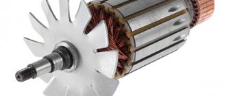
Single-phase motor device
Despite their name, single-phase motors have three coils in their design, and this is the minimum. Two of them are located in the stator and are connected in parallel. In this case, only one works directly, the second is called the launcher. The terminals of the working and starting windings are brought out to the body of the unit, with their help the drive is connected to the network. Two of them are connected to the network, all the rest perform switching functions. The rotor winding is made of a short-circuited type.
To be able to change the power of the device, the winding coil can be made of two parts. They will turn on sequentially.
You can determine the type of winding (working and starting) visually by paying attention to the cross-section of the wire and measuring the resistance using a tester. Let's talk in more detail about methods for determining the type of winding, how they differ and why they are needed in a single-phase motor.
Winding diagram in a single-phase electric motor
Why do a single-phase motor have two windings?
All electric motors discussed today have low power. The magnetic core of a single-phase machine contains a winding of two phases, this is the main (working) and starting. The latter does not take part in the direct operation of the engine.
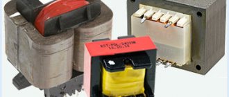
Such a pair of windings is needed to make the rotor of a single-phase motor rotate. The most popular of these drives are divided into two subtypes: electric motors with a starting winding and those that contain a run capacitor in their design.
In the first case, so to speak, the non-working winding will be turned on through the capacitor when the motor is started, and when the unit returns to normal operation (the rotation speed becomes constant), it will turn off by itself. The drive will continue to operate with one working winding. Information about the capacitor is usually indicated on a special plate on the motor housing. Its characteristics directly depend on the design.
Single-phase asynchronous motors containing a run capacitor always operate with the auxiliary winding switched on. It is turned on through this same capacitor. The capacity of such a capacitor also depends on its design features.
In other words, a motor with a starting winding is characterized by its turning off after starting. But with a capacitor auxiliary winding - its constant operation, because switching occurs through a constantly operating (even while the drive is running) capacitor.
To properly test the performance of a single-phase motor, knowledge of the design of its windings is critical. The differences between them can be found in the cross-sections of the wires, the number of turns, the resistance value of each of them (they can be measured with different types of testers or using an ohmmeter).
We learn to determine the starting and operating windings in single-phase asynchronous motors
Of course, having markings on the winding solves this problem. But often in case of repair or replacement of windings, it is not preserved. How then can you determine what kind of winding is in front of you? So we will discuss the theoretical and practical aspects of determining the starting and operating windings.
Inspect the product
For clarity, let’s take the engine that was installed in a washing machine during the USSR. The machine itself has been in scrap metal for a long time.
After a visual inspection of the nameplate on the engine, as in this case, you may not find it, but the age of the engine speaks for itself. In this case, all information can be found on the Internet. It turned out that the engine contains a starting winding and a relay start in its design.
Four wires are visible from the engine: two reddish, two bluish. These wires are also called winding leads.
Due to the absence of any markings, it is impossible to immediately determine which winding is the starting winding and which is the working winding. In such a situation, you need to pay attention to the cross-section of the conductors.
Section
Look at the wires that come out of the electric motor, or rather at their thickness. One of the pairs will be thinner. This is the starting winding. Therefore, the thicker pair is the working one.
It may happen that the cross-sections on both wires are the same, as in our situation. It is also impossible to visually determine where each winding is.
But if the difference in the thickness of the wires is noticeable, do not rely on the diameter alone. To determine the windings for sure, measure their resistance.
At this stage, we move on to measuring the resistance of the windings of a single-phase AC motor.
Final stage
Resistance measurement
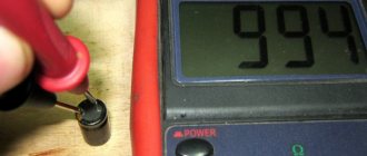
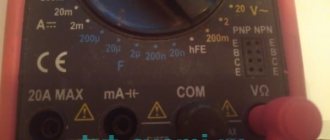
To measure the resistance of the windings of a single-phase motor, you will need a multimeter, on which you need to select continuity (or Ohm measurement mode).
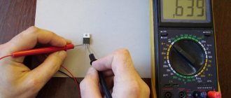
We connect the wires protruding from the electric motor (any pair) to any leads of the multimeter and measure the value.
If you see number one on the screen, repeat the measurement with any other end.
Record the resistance shown by the first selected pair (in this case it turned out to be 16.5 ohms). After this, the probes of the measuring device need to be attached to the two remaining terminals (the second pair of wires) and measurements must be taken.
The data obtained also needs to be recorded and then compared with the first measurement.
The resistance of a serviceable working winding will always be less than that of the starting winding. The second pair of wires, according to the multimeter, showed a resistance of 34.5 ohms. Thus, we can safely say that the first pair of wires indicates that they belong to the working winding, and the second, accordingly, to the starting winding.
Label both windings so that you don't have to do it all over again in the future. It is convenient to use a small vinyl tube for this.
You can mark the ends of the wires (terminals) according to modern standards like this:
- the signs U1-U2 mark the working winding;
- signs B1-B2 mark the starting winding.
Such designations are placed in cases where four terminals are visible from the engine, in a given situation. However, you may come across a motor that has only three terminals. What to do?
So, the measurements for each of the three pins will look something like this: 10 ohms, 25 ohms and 15 ohms. Having completed these measurements, you need to immediately proceed to others. It is important to find a pin that, with the other two pins, will show 10 and 15 ohms. Congratulations! You are our network wire. The pin showing a resistance of 10 ohms is also a network pin, and the one that showed 15 ohms is a starting pin. It is connected to the second network through a capacitor. By the way, to change the direction of rotation in such a motor, you will have to get to the winding circuit itself.
Sometimes the measurements can be 10 ohms, 10 ohms and 20 ohms. This is the norm, such windings also exist, they were also installed on various household appliances. The peculiarity of such an engine is that which winding will be the starting one and which winding will be the working winding does not matter at all. They are the same. Just one of them (the one that will be the starting one) needs to be connected through a capacitor.
So we figured out simple methods for recognizing starting and working windings. Now you can distinguish the components of the engine even if there is no nameplate and any pin markings. We offer a little summary of all the information:
- In the case where the motor has four terminals, you only need to find the ends of the windings, which are easy to disassemble after measuring. The wire where the resistance value is lower is the working winding, and the higher is the starting winding. Connecting all the terminals is very simple: 220 V voltage is supplied to those wires that are thicker. And one of the ends of the starting wires is on one of the working ones. At the same time, it does not matter at all what exactly the tip of the working winding output is on, because the direction of rotation does not depend on this in any way (as well as, say, on which side you insert the plug into the socket). The rotation only changes depending on which end of the starting winding you connect.
- If there are only three wires as the output of the windings, the network wire will be the one that shows the least resistance, as well as the one that, when connected to the other two, will show a resistance of 10 Ohms and 15 Ohms (if the resistance measurements of each of them gave 10 Ohms, 25 Ohms and 15 Ohm). The one that showed 15 Ohms on the multimeter is the output of the starting winding.
- If you come across a three-wire output, and the resistance of each wire (as an example) is 10 Ohms, 10 Ohms and 20 Ohms, both windings can be working and starting.
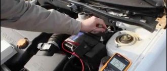
To identify electric drive breakdowns at home, it is enough to use a multimeter. Firstly, not everyone has expensive professional equipment (this is rather an exception), and secondly, this device is, as they say, sufficient to identify most faults. You don't need any specialist here.
The most basic malfunction in single-phase motors is stopping rotation. The cause of such a breakdown is determined quite simply. The multimeter is switched to voltmeter mode and the voltage supply that powers the engine is checked. If everything is in order with the voltage, then the fault lies in the engine itself, its electrical part. This, of course, indicates the need to check the connection status and ringing of the windings. For this, a multimeter is often also used.
But how to properly prepare for the engine ringing?
Peculiarities
Modern electrical equipment is equipped with motors with additional protective devices such as thermal fuses, thermal relays and engine speed sensors.
- Thermal fuses interrupt the power circuit at a certain engine heating threshold. Its serviceable condition will be indicated by the tester readings, such as a short circuit;
- Thermal relays replaced fuses. Some of them are in working condition with closed terminals, others, on the contrary, with open contacts. This is easily verified by a tester;
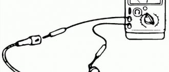
- Motor speed sensors are usually installed in washing machines. Three terminals of the device are used for testing. Having removed the contact chip, alternately move the red probe to the outer contacts of the sensor, and keep the black probe on the central terminal. When the rotor rotates in one of the options, the multimeter should demonstrate the dynamics of the readings.
Preparatory stage of verification
Short the multimeter probes
Before performing diagnostics, you must perform the following steps:
- Disconnect the machine from power. If the winding resistance is measured with the circuit connected to the mains, the unit will break down.
- Close the multimeter probes and set the values to zero. This is called calibrating the device.
- Inspect the engine carefully. It could be flooded, some parts could break off, and there might be a burning smell. In this case, there is no point in calling the unit, because the breakdown is obvious.
Asynchronous, single-phase and three-phase, commutator - all motors ring in the same way. The methodology does not differ depending on the difference in the design of the units, since all the differences are so fundamental. However, there are some details in the diagnosis that cannot be ignored.
Classification of CD
Depending on the type of power supply used, there are:
- motors operating on direct current - simple design, high starting torque, smooth frequency control;
- universal – capable of operating from a constant and variable power source. They have compact dimensions, simple controls, and low price.
The manufacturer indicates the technical characteristics of the unit on the plate. It is attached to the body. But modernization, repairs, changes in rewinding are factors that cause changes in passport information. This nuance must be taken into account when carrying out repairs.
In household power supply from 220V the following is used:
- collector installations equipped with a brush mechanism;
- asynchronous single-phase unit;
- three-phase synchronous and asynchronous electrical machines.
380V electrical systems use three-phase synchronous and asynchronous electric motors. They have different designs, but operate according to general principles of electrical engineering, which allows the same testing methods to be used. The latter consist of measuring electrical characteristics indirect/direct ways.
Directly checking the engine with a multimeter
The most common breakdowns are divided into two main groups:
- there is contact where it should not be;
- there is no contact where it should be.
Let's look at how to ring a single-phase AC electric motor using a multimeter. It has two coils, one of which is working and the second is auxiliary. The level of reliability of contacts, the quality of insulation and the correctness of winding have a huge influence on the level of engine performance.
- The first thing to do is check for a short to body. Here you need to remember that all values on the multimeter will be approximate. To obtain accurate data, more expensive and accurate measurement devices will be needed.
- The measurement values on the device are set to maximum.
- The probes are connected to each other. This way you can make sure that the multimeter itself is working and configured correctly.
- Then one probe is connected to the drive housing. If there is contact, you can also connect a second probe. Track your readings.
- If nothing goes wrong, touch the phase output with the probe.
- With high-quality insulation, the device will show a high resistance value. It can be within even several thousand megaohms.
Remember that when measuring insulation resistance with a multimeter you will always get high readings (above acceptable standards). This is due to the fact that the electromotive force of the device is a maximum of 9 V, and the engine, as we know, performs work with a voltage of 220 V or even 380 V. Ohm’s law says that the amount of resistance depends on the amount of voltage, so you should always make allowance for the difference .
It is also mandatory to check the integrity of the windings. It is necessary to ring all the ends that enter the terminal box of the unit. If there is a break, then it is better to stop the test, because there is no logic in further diagnostics. You need to work on solving this problem first.
Knowing the rules and procedure for ringing a single-phase motor using a multimeter, you can easily save on diagnostics and repairs when the motor actually has only minor breakdowns. But if you realize that everything is not so simple or simply do not understand what is wrong with your electric motor, it is better to take it to a professional who will conduct a more detailed check with expensive and sensitive instruments.
To identify and repair a problem with a brushed motor, it will most likely have to be disassembled.
Frequent malfunctions
Before disassembling, be sure to look for sparking, which usually occurs in the contact-brush mechanism. If you notice an increased level of sparking, it is worth checking the contact of the brushes or the presence of an interturn short circuit in the commutator itself.
As a rule, the main reasons why commutator motors break down are severely worn brushes or a blackened commutator. Old brushes are usually replaced with new ones. They must be the same in size and shape. It is best to install original parts (from the same manufacturer as the engine). Changing them is quite simple: remove (move) the lock or unscrew the bolt. Some engine models may require changing not only brushes, but also brush holders. Don't forget to connect the copper lead to the contact.
If the brushes are normal, check the springs that press them by stretching them.
If the contact part of the commutator becomes dark, clean it using fine sandpaper. It is also called zero.
At times, a groove forms at the point where the brushes and commutator come into contact. It needs to be sharpened using a machine.
Single-phase brushed motor
Another common failure of a commutator single-phase motor is bearing wear. If the housing vibrates strongly during operation and the bearings break, they definitely need to be replaced. If you start the situation, the mentioned parts will touch the rotor and stator, which may lead to their inevitable replacement. This is already more difficult and more expensive.
Rare malfunctions
Breaks and burnouts of windings and connection points occur much less frequently in commutator motors. It is also rare to see melting and shorting of the lamella with graphite dust.
To avoid such breakdowns, during an external inspection you should always pay attention to:
- integrity of windings;
- presence of blackening on the windings;
- the strength of contact between the collector lamellas and the wire leads. If necessary, they need to be re-soldered;
- the amount of graphite dust between the collector lamellas. Be sure to remove dust if necessary;
- presence of a burning smell (this may be insulation).
During a visual inspection, did you find that the stator/rotor winding is damaged? Rewind it or simply replace it with a new one.
Unfortunately, damage to the winding cannot always be seen with the naked eye, so if there are no obvious breakdowns, check them with a multimeter.
Checking the capacitor with a multimeter
Of course, the most reliable way to test a faulty single-phase motor with a capacitor is to use an ohmmeter to measure the resistance value. The device will accurately show the resistance of the capacitor, and from this it is already possible to draw conclusions about how integral the dielectric is, on which the serviceability of the electronic device directly depends.
In everyday life, when no one requires exact values from you, and you only need to find out the cause of the breakdown, a multimeter will be enough.
The verification algorithm is as follows:
- the multimeter switches to Ohm measurement mode;
- then you need to set the upper resistance value - infinity;
- measure the resistance of the capacitor at the terminals.
If the resistance is low (and this is any value other than infinity), then the device that passes the test is broken. Here either the dielectric is broken or the electrolyte has leaked.
Does the dial needle on the tester show a slight deviation and then return to its original position? The capacitor is working properly and is slowly gaining capacity.
A device needle that deviates and then fixes on one of the values also indicates a breakdown of the electronic device.
As we have already found out, a multimeter is an indispensable device for quickly and multidisciplinary checking engines for serviceability. It can be found in all specialized craftsmen and in many home workshops. With its help, you can identify the main types of breakdowns of electrical appliances, and engines are no exception.
The most common breakdowns in electric motors and other machines of this type are the following:
- broken winding on the rotor or stator;
- presence of a short circuit;
- the presence of an interturn short circuit.
Each issue on the list above deserves a closer look.
The winding has broken
There is nothing surprising about a winding break; this is the most common malfunction in the operation of electric drives. A breakdown can occur in both the stator and the armature.
If one phase in the winding breaks, then there will be no current in this place, but in the second phase the current indicator will be overestimated. This can be measured using the same multimeter in ammeter mode.
In general, this failure is equivalent to a loss of phase. For example, if a break suddenly occurred while the drive was in operation, the engine begins to sharply lose power and overheat. If the protection on the unit is working correctly, it will turn off. Solving the problem basically requires rewinding.
In a situation where a break has occurred in the rotor, the frequency of current oscillation will be equal to the frequency of voltage oscillation and slip. External signs: strong buzzing and vibration, decreased drive speed.
All these are just causes of breakdowns, but they can only be detected if you ring each winding of the electric motor and measure their resistance.
The starting and working windings are connected in those single-phase motors that operate at an alternating voltage of 220 V. The starting winding must produce a resistance that is 150% greater than that of the working winding.
To quickly check the performance of the electric motor, you can also use a function on the multimeter called “Dialing”. If the circuit is working properly, you will hear the characteristic sound of the device, and in some models there is also a light indicator. But if there is a break in the circuit, you will not hear any sound.
What tools are needed
First of all, you will need the device itself. But before you test the electric motor with a multimeter, you need to know the operating principles of this device.
The main functions of a standard meter allow you to measure with sufficient accuracy:
- the amount of active resistance of the circuit to electric current;
- constant pressure;
- AC voltage.
Some models additionally allow you to check:
- continuity of the electrical circuit;
- capacitance value of the capacitor.
To open the housings of equipment and motors, you need screwdrivers, wrenches, pliers, and a hammer. Thanks to this set, as well as minimal knowledge in electrical engineering, the question of how to check an electric motor with a multimeter makes it easy to identify faults that can be corrected independently.
Complex damage is eliminated by service workshops that have precision equipment.
Checking for short circuit
One of the common failures in electric motors is a short circuit to the frame. To find this kind of breakdown with a multimeter, do the following:
- set the resistance measurement of the device to maximum;
- check the serviceability of the multimeter itself by connecting its probes to each other;
- Connect one of the probes to the engine body;
- Connect the remaining one in turn to each of the phases.
If the engine you tested is working properly, then the resistance will show hundreds and even thousands of megaohms.
It is even easier to investigate for a short circuit in the “Dialing” mode. You need to do the same steps, and if you hear a sound (as when the winding is being tested), this will indicate the presence of violations in the integrity of the winding insulation, as well as the presence of a short circuit to the housing.
It should be noted that a breakdown of this type not only has a negative impact on the engine itself, but is dangerous for the lives of people working with the machine (if the necessary protective equipment is not available).
conclusions
Checking the condition of the electric motor with a multimeter with a positive result can be characterized by the fact that all parallel measurements of the stator and rotor contacts must be the same. In case of deviations from these requirements, you need to look for a breakdown or break in the conductors at the measurement sites. It should be taken into account that household testers often allow some measurement error. Unlike digital instruments, pointer instruments are more accurate. To check this, in the 200 Ohm mode the probes are short-circuited. “0” or another number from 0.1 to 0.2 Ohm should appear on the screen. This will be the tester's error.