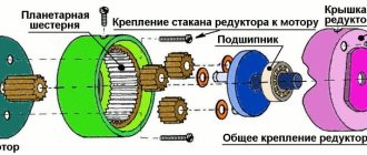
Pulley
, a drawing with dimensions of a part that is part of a belt or rope drive that transmits torque (force) from the shaft to the drive belt or rope.
A mechanism that consists of two pulleys (mounted and fixed on axles) and an annular drive belt located between them is usually called a belt drive.
A pulley is a drive wheel for transmitting or receiving torque from a drive belt. Belt drives have been used by people since ancient times; in the Middle Ages, their widespread use in village spinning wheels began. With the beginning of the industrial revolution, every machine was equipped with them. Nowadays, pulleys are widely used in internal combustion engines, machine tools, household appliances, and hand-held power tools. Drive belts and wheels have been standardized - this allows them to be interchangeable. The rules and techniques for depicting parts in drawings have also been standardized.
Pulley concept
It is designed to transmit torque from the drive shaft to the driven shaft. To operate such a drive, both shafts are placed in parallel. A flat wheel is put on and secured to each shaft; they are placed in the same plane. The wheels are connected by an endless flexible drive belt. When the drive pulley rotates, the friction force causes the belt to move, covering part of its surface. This motion is transferred to the driven pulley, causing it to rotate.
Belt drives are common among household appliances, mechanisms of low- and medium-power machine tools, and in various internal combustion engines.
It has the following advantages:
- simple device;
- the ability to transmit significant power, modern V-belt pairs transmit up to 400 kW;
- high rotation speed, up to 50 m/s;
- smooth and quiet running;
- damping of vibrations and jerks of the drive shaft during rotation transmission;
- slippage under overloads acts as a safety mechanism.
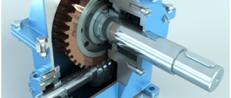
The pulley itself is a disk on a shaft. It consists of two main parts: the rim and the hub. The rim is the outer part of the part. It engages with the belt and, depending on the type of drive, can be flat or have a recess in the shape of the belt. The side projections above the rim are called cheeks. They keep the belt from slipping. If the drive is wedge, then the cheeks are made inclined; they have an additional function - they increase the engagement area.
If a gear drive is used, then teeth of the appropriate shape are made on the surface of the rim.
If several streams are used in parallel, several grooves are made on the rim.
The hub is the inner part of the pulley. It has a hole for mounting on the shaft. Often the rim and hub are cast, turned, or milled as a single piece.
To reduce the weight of the product, voids are left in the body of the pulley, forming spokes. When made from wood, the presence of knitting needles was determined by the manufacturing technology.
To ensure the interchangeability of pulleys, their standard sizes, technological requirements, and markings are standardized. They are described in GOST 20889-94. “Pulleys for driving V-belts” and in GOST R 50641-94 (ISO 4183-89).
Standard markings include the following parameters:
- number of streams;
- profile of the drive belt used;
- diameter (calculated by cord);
- sleeve designation.
Thus, the marking 8 SPC 500 indicates an eight-lane pulley for an SPC profile with a diameter of 500 mm.
The rules for depicting pulleys in the drawing have also been standardized. The drawing must be constructed so that the product can be manufactured to exactly the same shape and size.
Purpose and device
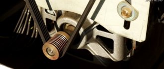
In the vast majority of cases, the outer part of the pulley is a disk with a periphery, which are connected by especially durable rubber. You can notice small notches and pits on the pulley - they are needed so that the part, which is mostly a heavy metal product, is balanced . A well-balanced pulley copes with the following tasks:
Types of pulleys
Over thousands of years of use, designers have developed many designs of belt pulleys. Their classification is carried out according to various criteria.
Read also: The simplest DIY digital antennas
Depending on the type of belt used, there are:
Wedge-shaped
The most common type of product. Used with V-belts. The side cheeks provide additional engagement area, increasing the transmission capabilities of torque and rotation speed.
The inclination of the groove must be indicated on the part drawing.
In order to reduce the dimensions of the transmission or increase its power, several streams are launched in parallel. Such pulleys are called multi-grooved; they have the appropriate number of grooves. Sometimes a single belt with several wedge-shaped protrusions is put on such a pulley. This is a poly-V transmission.
In the drawing it is permissible to give a detailed image of one groove and indicate their number. Detailing of the rest in the drawing is not required
If the permissible load is exceeded in an emergency, slipping begins, protecting the equipment from damage.
V-belt transmissions allow you to transmit the highest torque.
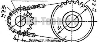
Serrated
There are toothed projections on the inner surface of the belt; teeth corresponding to their pitch are also made on the surface of the rim. Gear-belt pairs do not slip and can transmit more torque. They are also distinguished by the accuracy of transmitting the angular position of the shaft, therefore they are used in gas distribution mechanisms of internal combustion engines. The downside is the lack of a protective function against overloads. The rim is made by milling. There is also production by the rolling method. The detail drawing must indicate the exact parameters of the tooth, its pitch, height, and profile.
Flat-shaft
A classic design used in the very first gears. Absorbs vibration and dynamic loads from the drive shaft. They are characterized by low noise, limited torque and rotation speed.
Using additional rollers, you can connect driven and drive shafts that are in different planes, not coaxial, and change the direction of rotation. In this way, cardan and worm gears can be replaced. The drawing of such a product is the simplest, but it should indicate the radii of the rim and cheeks, if provided. Sometimes cheeks are not provided, and the rim profile is made convex. In this case, its radius should be indicated on the drawing.
Round belt
The groove in the rim has a semicircular profile. Such belt drives are used for low transmitted torques and rotational speeds. They also allow you to change the direction of rotation and connect axes located in different planes. In the drawings of such parts, only the radius of the groove is indicated.
CVT
These are the most complex devices in design. The rim is made in the form of a cone with a conical moving cheek. The V-belt ring has the ability to move along the cone in the axial direction, from a smaller radius to a larger one. The second pulley has a reverse taper, and the drive on it moves from a smaller radius to a larger one. In this case, the transmission ratio changes. The cheeks of both pulleys can move in the opposite direction, changing the gear ratio in the opposite direction.
The advantage of the design is that the gear ratio can be changed without stopping rotation and without removing the load from the drive. It can be difficult to understand the operating principle of a device from a drawing. Three-dimensional modeling allows you to supplement models with kinematic simulations that clearly demonstrate the interaction of mechanism parts.
Pulleys are also distinguished by the method of placement on the shaft:
- Under the sleeve. Allows you to secure the drive on any standard shaft by selecting a bushing of the appropriate internal diameter. If the seat is damaged, it is enough to replace the bushing, which makes repairs easier and faster.
- Under boring. Available with a small central hole. It is bored or drilled to fit the diameter of the shaft. If damaged, it is difficult to repair.
- Fixed diameter. Usually equipped with a groove for keyed fastening or splines. Very simple and quick installation and dismantling. Requires exact matching of diameters. Allows the production of molded parts.
Read also: Pulse tachometer for chainsaws
For the manufacture of parts, materials such as are used:
- Cast iron. Widely used for V-pulleys. It is characterized by high strength, low price of products and ease of processing.
- Steel. It is used in mechanisms subject to large temperature changes and strong dynamic loads.
- Aluminum and its alloys. Used for lightly loaded gears in mechanisms for which weight and dimensions are important. Not subject to corrosion.
- Plastics. Used in small-sized devices with low transmitted torques and speeds.
- Composite materials. They are used in advanced technology, where a combination of low weight, high strength, resistance to dynamic loads and adverse environmental influences is required. They are distinguished by their high cost.
The drawings indicate not only the grade of the alloy, but also the method of its processing, surface cleanliness, hardness, the need for hardening, etc.
Wood, as a traditional material for belt drives, has fallen out of use these days. It is used in the reconstruction of historical mechanisms and in homemade products. Drive wheels glued together from plywood rims are sometimes used as a temporary repair part in home workshops.
Steel, cast iron or aluminum?
The suspension arms are the central element that determines the characteristics of the entire assembly. It is the levers that take on the shock load from the wheel, movably connecting the unsprung mass (wheel and hub) with the sprung mass (subframe or frame). Automakers choose steel, cast iron or aluminum as the material for wishbones. The choice of material is dictated by many inputs - from physical indicators to production costs.
Steel is a classic choice for a control arm. Steel is cheap and ductile, and stamping is a simple, mass-produced method for producing parts. Historically, steel is the most popular material for suspension arms. Lightweight stamped levers make it possible to reduce production costs and make more mass-produced and affordable cars. Steel levers, due to their elasticity, “smooth out” impacts from the wheel well. Thanks to this same elasticity, steel levers are often “reusable” - by pressing silent blocks or ball joints into levers, it is possible to reduce the cost of suspension repairs. An important feature of any iron, including steel, is the need for protection against corrosion. Steel levers, as well as cast iron (which will be discussed later), require a coating - for example, cataphoretic painting, which is used in the production of Delphi Technologies levers.
However, the elasticity of steel is a double-edged sword. Elastic metal obviously does not have sufficient rigidity, which is why the levers have to be structurally reinforced, for example, using stiffeners. However, in cases where high rigidity is required to ensure good handling, steel is not very suitable. This is how manufacturers came to forged levers. Cast iron parts are made using the forging method - their strength and rigidity are much higher than steel ones. The cast iron arms are heavy and durable and provide a stiff and composed suspension. They are also indispensable for heavy vehicles with wishbone suspension. Forged levers also have disadvantages - when the designed load is exceeded, such a lever does not bend like a steel one, but breaks, since cast iron is, paradoxically, a strong but fragile material. Rigid cast iron levers, without deformation, transfer impacts to the subframe, which in the event of an accident can lead to more serious damage. In addition, forged cast iron levers are simply heavy.
It was in search of a lighter material that manufacturers turned to aluminum. With equal strength characteristics, an aluminum lever is much lighter than any iron lever - steel or cast iron. For a long time, aluminum suspension arms were the exclusive privilege of sports cars, in which there is a struggle for every kilogram. However, as production developed around the world, the price of aluminum began to decline, which made it possible to more widely introduce this metal in ordinary mass-produced cars, in particular in suspension elements. Aluminum levers are not only light, but also durable - aluminum alloyed with certain additives has characteristics closer to cast iron than to steel. The elasticity of aluminum levers is much lower than steel ones, so rigidity and controllability with such levers is higher. However, if damaged, it, just like a cast iron lever, is prone to cracking. This, in particular, explains the impossibility of repressing ball joints and silent blocks into aluminum - it simply cracks. But such levers do not require protection, since aluminum in air is instantly covered with a thin oxide film, which prevents further corrosion.
Based on a set of characteristics, manufacturers choose the material for the suspension arm of a particular model. Steel is cheap, elastic, suitable for budget mass models. Cast iron is durable and provides controllability, but is heavy. Aluminum is the most expensive, but it is lightweight, which ultimately reduces the overall weight of the car, which means it increases energy efficiency. It is important to understand that the choice of material for suspension arms is always a balance between positive and negative characteristics, and the manufacturer chooses a certain material for a reason. Therefore, if replacement is necessary, you should pay attention to the exact correspondence of the spare part to the original part - this also applies to the material.
Also, when choosing a spare part, it is important to ensure its reliability. Thus, for its suspension arms, Delphi Technologies uses tests, the number of cycles of which reaches up to 250 thousand. All levers undergo thorough flaw detection. By the way, Delphi Technologies produces all types of levers: steel, cast iron and aluminum, depending on what material the car manufacturer provided. Regardless of the choice of material, Delphi Technologies levers are original quality and high reliability.
Source
Application of pulleys
Wedge drives are one of the most widely used in a wide variety of mechanisms and devices with high torque and angular velocity. First of all, these are internal combustion engines. In addition, V-belt pairs are used in areas such as:
- fans and air conditioners;
- compressor units, both piston and screw;
- transport systems of buildings: elevators, escalators, travelators;
- agricultural machinery;
- road construction equipment;
- mining machines;
- industrial technological installations;
- machines;
- Appliances;
- hand power tools;
and in many other industries.
Gear drives are used in cases where it is necessary to transmit significant torque without slipping. The toothed belt drive does not require much tension for good traction. It produces significantly less radial load on the axle than other belt drives.
The following drives are used in:
- automobile engines, for the gas distribution mechanism;
- power drives of machine tools and industrial mechanisms;
- in technological installations of the food, pharmaceutical, chemical industries.
Poly V-ribbed pulleys do an excellent job in so-called serpentine transmissions, when one drive supplies rotational energy to many consumers, and at the same time follows a very winding trajectory. Poly V-ratio transmissions allow you to transmit significant torques and achieve high speeds without increasing dimensions.
They are used both in heavy engineering and in the production of household appliances.
CVT drive wheels are used wherever it is necessary to smoothly change speed and torque without stopping rotation or removing the load. They are popular in areas such as:
- transmissions of cars, motorcycles, and other wheeled vehicles;
- conveyors;
- precision machines for processing metal, wood and other materials;
- agricultural machinery.
A modern variator surpasses both manual and hydraulic transmissions in its performance characteristics.
Flat drives are used where it is necessary to transmit rotation over significant distances (up to 7-9 m) and absorb shocks, jolts and other dynamic loads transmitted from the drive shaft to the driven shaft (or in the opposite direction). They apply:
- in pressing and other forging equipment;
- in sawmill drives;
- in technological equipment of the textile industry;
- in powerful centrifugal pumps.
Round belt drives are used for light-duty transmissions in precision instruments, consumer electronics and appliances.
They also easily intersect and, with the help of additional passive pulleys, allow you to connect the driven and drive shafts, located in different planes and at an angle to each other, and also change the direction of rotation.
Determining the length of the V-belt
Various length measurements are used for V-belts:
- Li = internal length
- Ld/Lw = base length (this indicator is classified according to the ISO standard)
- La = outside length
Which indicator (external or internal length) is displayed on the belt is determined by the manufacturer himself. Traditionally, for classic V-belts (VB), the size or type designation is the internal length (Li) plus a letter indicating the profile size. For other types of belts, the base length is used to indicate the length (Ld/Lw). The width of all types of V-belts is also fixed.
Dimensions of different types of V-belts
Pulley image in the drawings
From the drawing of the product, its structure, dimensions and manufacturing method should be completely clear. For standard products, the designation of the pulleys must be indicated on the drawing.
Read also: Making balls on a lathe
In order to correctly and accurately manufacture a non-standard pulley, its drawing must meet certain requirements. You can choose the correct angle of the pulley groove if you use a standard series of slopes for the drawing.
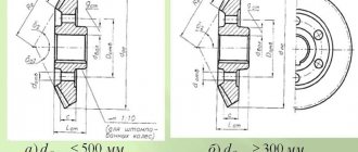
The pulley is usually depicted in drawings in two forms:
- section by a secant plane passing through the axis of rotation;
- side view.
The side view, as for other parts with axial symmetry, is not shown in full, but in half. For pulleys that have spokes in their design, it is permissible not to depict everything, but to provide a drawing of one part indicating their number.
The incision must be constructed so that there is at least one spoke in its plane. There is no need to hatch the spokes on the section. If the part is made solid, the cut plane is hatched, as usual in the drawing.
Main dimensions and parameters, such as:
- rim and hub diameter;
- V-belt profile;
- mating radii;
- groove slopes, etc., are marked on the cut.
An additional view of the drawing shows a cross-section of a spoke. If its shape is variable, then several additional types of drawing are made.
An image of the mounting location for the key with dimensions and an indication of the surface quality is also shown in an additional view of the drawing.
If instead of knitting needles, to facilitate the construction, several holes are provided in the body of the part, their number and dimensions are indicated on the section, and it is permissible not to construct a side view in the drawing.
If you find an error, please select a piece of text and press Ctrl+Enter.
Pulleys for V-belts: purpose and manufacturing features
A pulley is a metal wheel with a groove or rim used to transmit rotation from one unit to another. The size of the pulley groove is determined by the size and overall parameters of the belt in a particular mechanism.
Contact phone number: WhatsApp .
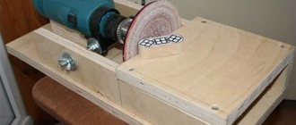
Pulleys for V-belts are made on a special lathe. The material used for such products is metal. Most often, cast iron, aluminum, steel, textolite and caprolon are used for these purposes. Despite the simplicity of the part, its manufacture requires not only specialized equipment, but also certain skills of the craftsman. It is for these reasons that even if the equipment is available, it is better to order the manufacture of this part from a specialist.
If the pulley is manufactured correctly, it is possible to extend the service life of not only the belt, but also the drive mechanisms and components.
Methods for making pulleys for V-belts
The method and material of manufacturing pulleys for V-belts directly depends on the speed of rotation of the belt.
- At a maximum belt speed of up to 30 m/s, cast iron SCh20 is used;
- At belt rotation speeds of up to 40 m/s, 25L steel is used. The part is produced by injection molding and sharpened on a lathe;
- Rotation speed up to 60 m/s. In this case, prefabricated or cast pulleys made of steel 30 are used;
- With a maximum rotation speed of up to 80 m/s. In this situation, cast pulleys made from various metal alloys AL-3 ML-5 are usually used;
- At rotation speeds up to 100 m/s. In this case, forging or casting can be used, followed by turning. In the first case, chromium steel is used, in the second, duralumin.
The cost and choice of pulley depends on the speed and force of rotation transmitted from one unit to another using a belt. The price of such a product depends on the material, manufacturing method and its dimensional parameters.
TECHNICAL REQUIREMENTS
2.1. Pulleys for driving V-belts must be manufactured in accordance with the requirements of this standard according to working drawings approved in the prescribed manner.
2.2. The nominal design diameters of the pulleys must correspond to the indicated series: 50; (53); 56; (60); 63; (67); 71; (75); 80; (85); 90; (95); 100; (106); 112; (118); 125; (132); 140; (150); 160; (170); 180; (190); 200; (212); 224; (236); 250; (265); 280; (300); 315; (335); 355; (375); 400; (425); 450; 475; 500; (530); 560; (600); (620), 630; (670); 710; (750); 800; (850); 900; (950); 1000; (1060); 1120; (1180); 1250; (1320); 1400; (1500); 1600; (1700); 1800; (1900) 2000; (2120); 2240; (2360); 2500; (2650); (2800); (3000); (3150); (3550); (3750); (4000) mm. Note. The dimensions indicated in brackets are used in technically justified cases.
2.3. The design diameter of the smaller transmission pulley must be no less than the values specified in Table 1
Table 1
| Belt section designation | Design diameter of the smaller pulley, mm |
| Z | 63 (50) |
| A | 90 (75) |
| IN | 125 |
| WITH | 200 |
| D | 315 |
| E | 500 |
| EO | 800 |
Note. The dimensions indicated in brackets are used in technically justified cases.
2.4. The profile dimensions of the pulley grooves must correspond to those indicated in Figure 10 and Table 2.
Options for replacing V-belts by length
All drives using V-belts have a tension, given the huge number of types of drives and their sizes, there are a lot of options for changing the length of the belt up or down. Therefore, let’s look at the most common examples of belt replacements by length.
— If the belt length is less than 1000 mm, then the belt can be installed +- 10 mm from the previously installed one, — If the belt length is from 1000 to 1500 mm, then the belt can be installed +- 13 mm from the previously installed one, — If the belt length is from 1500 to 2000 mm, then the belt can be installed +- 17 mm from the previously installed one, - If the belt length is from 2000 to 2500 mm, then the belt can be installed +- 19 mm from the previously installed one, - If the belt length is from 2500 to 3000 mm, then the belt can be installed +- 22 mm from the previously installed one, - If the belt length is from 3000 to 4000 mm, then the belt can be installed +- 30 mm from the previously installed one, - If the belt length is more than 4000 mm, then the belt can be installed +- 40 mm from the previously installed one.
In 99% of cases, this difference in belt length is compensated by a tension pulley, which is necessarily present in all types of drives using a V-belt. The shift on the tension pulley fixing bar will be 2 times less than the change in belt length. That is, if we install a belt 20 mm longer than the original, then the fixing bolt on this bar will move only 10 mm.
The selection of a V-belt based on cross-sectional dimensions and length can be performed by specialists from TPK Beltimpex LLC. For questions regarding purchase and cooperation, please contact the company's sales department.
Calculation of V-belt length
When using rubber products, their geometry changes up to 10%, and this feature greatly simplifies the selection of V-belts by length.
The selection of European and American V-belts is carried out according to sizes that differ from GOST 1284.1-89.
The European standard DIN 2215 is marked with the profile number and length along the inner radius. The American RMA standard also specifies the inner radius length in inches. Measurements are taken in a free, non-tensioned position. Calculation of the length of a Russian-made V-belt must be done according to the cord.
The internal length of the V-belt can be measured directly from the position it occupied on the drive pulleys using a flexible tape measure or tape measure.
Find out the country of manufacture
If there are any identification marks left on the belt, try to determine from them whether it is imported or domestic. If the product is made in Russia, you will need to measure its working length. It is listed in catalogs with the designation Lw.
If you need to buy imported V-belts, you will need to measure the internal length. In the catalogs of European manufacturers, it is indicated under the marking Li and is indicated in millimeters. American-made belts are measured in inches, so sizes will have to be converted from one measurement to another. If the profile height of Russian and European belts is indicated by numbers, then for American products it is indicated by letters.