Anyone who has ever heard of motors used in industry has probably heard the term "geared motor".
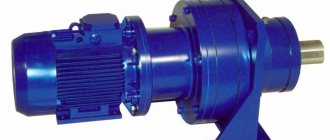
A gear motor is a drive machine that consists of a motor and a mechanical gearbox combined into a single unit.
The main purpose of geared motors is, first of all, to change the speed of a moving machine, change the torque on the output shaft and drive transmission. Most often, this is a decrease in shaft rotation speed and an increase in torque.
High rotation speeds and relatively low torques are the main characteristics of typical electric motors. However, in order for them to be effectively used as a drive in industry, their parameters sometimes must be exactly the opposite. This is what gear motors are used for. Due to its compact design, a geared motor takes up several (and sometimes even tens or so) times less space than a “spaced” drive system.
Advantages of gearmotors
The most important advantage of geared motors is their small size and the placement of almost the entire machine drive system in one place, in one housing. The designer does not need to focus on the selection or design of individual components, he only selects a geared motor from a catalog of standardized models based on specified parameters. It is also worth noting the reliability of these units; high-quality equipment very rarely fails. With proper operation, the guaranteed service life can be tens of thousands of hours.
Specifications
The technical characteristics of the gearmotor are a complex of individual parameters of the mechanical part and the electric motor. The most important characteristic is the operating mode of the mechanism. In foreign literature, a similar parameter is used, called the service factor. It determines the frequency and level of mechanical loads and is set based on the characteristics of the technological process. The operating principle of the gearbox and its gear ratio allow you to select a model with the required type of engine for specific operating conditions. The shaft arrangement allows for the best positioning of the drive module on the equipment. The output shaft type ensures easy installation. An important parameter is the method of attaching the gear motor to the technological device. There are foot-mounted, flanged and combined models available.
In order to determine specific output shaft speeds, the rated rotation speed of the electric motor is used. Depending on it, the same gearbox will provide different characteristics. Engine power determines the load of the technological mechanism.
Application of geared motors
This type of device is most often used in industry, factories and production workshops. Almost every conveyor belt drive that transports heavy objects uses a motor in combination with a gearbox. Because here it is necessary to clearly indicate that the device is usually non-separable, i.e. the motor and gearbox have a common housing.
Although gearmotors may look similar in appearance, they often have different parameters. The choice of the appropriate model depends only on the preferences of the buyer. To meet all user expectations, gearmotor manufacturers can produce them to specific order and individually adapt them to the needs of the recipient. As a result, the customer receives a product that represents the optimal individual solution.
Design and principle of operation
The design of the gearmotor consists of a mechanical gearbox and an electric motor connected into a single unit. Due to this, the process plant requires one installation location instead of two. There is also no need to ensure the alignment of the motor and gearbox shafts, or to select and install a coupling that transmits rotation. The general design of the gearmotor has some differences from the separate options. The transmission housing is manufactured with the necessary safety margin to ensure reliable operation of the device with a fixed heavy motor. To mount the engine on the housing, special seats are made. The design of the gearbox drive gear includes cylindrical holes used to install the drive motor shaft. The housing is additionally provided with fastening elements for mounting the geared motor into the process unit. Any type of electric motor can be used as an electric drive for the gearmotor. The most common models are those using standard asynchronous electric motors. To implement a monoblock design, flange-type models are chosen.
The operating principle of a gear motor does not differ from the operation of a classic electric gear drive. The rotational torque of the engine is transmitted to the drive gear, which is actually mounted on the motor shaft. Thanks to gearing, the torque is converted by one or more driven elements, which in turn influence the shaft of the technological mechanism.
The output rotation speed depends on the motor parameters and the gear ratio. To obtain an increased conversion factor, multi-stage models are used. If speed correction is necessary, geared motors are easily integrated into systems with speed control via controlled converters.
Turret rotation gearbox
If you have heavy equipment, it will be difficult to do without a turret rotation gearbox. This mechanism allows you to operate the rotating part of the crane.
The equipment has a large gear ratio. This is a drive device that allows the turntable of a tower crane to rotate around its axis.
The system consists of an electric motor, the gearbox itself and the brake. Thus, rotation of the tower is possible together with the boom. The rotation gearbox consists of a cast steel housing containing three pairs of gears. They transfer the load.
The complete set of a tower crane cannot do without this device, which greatly facilitates the work process.
Characteristics of the main varieties of this device
Various types of gears are used in the design of the planetary gear set of automatic transmissions. There are three main most common ones: cylindrical, conical and wave.
Cylindrical
Gear mechanisms transmit torque between parallel shafts. The design of a cylindrical gear includes two or more pairs of wheels. The shape of the gear teeth can be straight, oblique or chevron. The cylindrical circuit is simple to manufacture and operate. Used in gearboxes, final drives, drives. The gear ratio is limited by the size of the mechanism: for one wheel pair it reaches 12. Efficiency is 95%.
Read
Which gearbox is more reliable and better: robot, CVT or automatic?
Conical
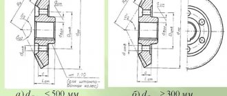
Wheels in a conical design convert and transmit rotation between shafts located at an angle of 90 to 170 degrees. The teeth are loaded unevenly, which reduces their ultimate torque and strength. The presence of forces on the axes complicates the design of the supports. For smooth connection and greater endurance, a circular tooth shape is used.
The production of bevel gears requires high precision and is therefore expensive. Angular structures are used in gearboxes, valves, and milling machines. The gear ratio of bevel mechanisms for medium-duty equipment does not exceed 7. Efficiency is 98%.
Wave
In wave transmission there are no sun and planetary gears. Inside the crown wheel there is a flexible oval-shaped gear. The carrier acts as a wave generator, and looks like an oval cam on a special bearing.
A flexible steel or plastic wheel is deformed under the action of the carrier. Along the major geometric axis, the teeth engage with the crown to the entire working height; along the minor axis there is no engagement. The movement is transmitted by a wave created by a flexible gear wheel.
In wave mechanisms, the efficiency increases along with the gear ratio exceeding 300. Wave transmission does not work in circuits with a kinematic characteristic below 20. The gearbox produces 85% efficiency, the multiplier - 65%. The design is used in industrial robots, manipulators, aviation and space technology.
Selection and service
The selection of a gearmotor is carried out based on the operating mode, required power and speed of the technological mechanism. The location of the shafts and individual parts of the device is also taken into account. The complete calculation of a geared motor in domestic practice is no different from the classical options for calculating the required gear. In order to simplify this operation, most manufacturers provide ready-made input and output parameters that allow selection to be made without complex calculations.
Which wheel motor is better, direct drive or geared?
We are often asked which wheel motor is better, geared or direct drive. We will not give a definite answer, since each of these two types of motor has its own advantages and disadvantages. For some, one thing will seem important, for others another.
To save your time, we’ll write a short excerpt:
- If you need speeds above 30 km/h, then you need a direct drive wheel motor with a power of 500 W or more, but be prepared for the fact that when the motor is turned off there will be a slight resistance when driving, and if you want confident climbing uphill , then the power should be 1500 W or more.
- If you are satisfied with speeds of up to 30 km/h, then a 350 W geared wheel motor is suitable for you, and you will get confident uphill climbing, no resistance when driving with the engine turned off, as well as low weight and dimensions of the motor. If this suits you, then the disadvantages of a gear motor are no longer significant.
- Both wheel motors are brushless.
Geared motor-wheel 250-350 W.
To begin with, we will briefly tell you what a gearbox is and why it is installed in an electric bicycle motor. A gearbox is a device that increases the torque of the wheel motor, but at the same time reduces the maximum speed to 30 km/h. That is, driving up a hill will be easy, but on a straight road the speed will be low. It's the same as driving a car in first or second gear. With a direct drive wheel motor, the same torque will be available at 1500 watts.
The gearbox consists of a planetary gear with three plastic gears inside. The service life of these gears depends on the operating mode and averages 6-9 thousand km. Replacing gears is not a difficult task, it takes 1-2 hours, and their cost can be found here. There are modifications with steel gears, but this is rare, since such motors are quite noisy.
Geared motor wheels have no resistance when driving with the motor turned off. In other words, if your battery runs out, you can ride like a regular bike. Good rolling is ensured by the presence of an overrunning clutch, which mechanically disconnects the motor from the wheel; it can be compared to a ratchet on the rear wheel of a bicycle - when you need it, you start pedaling and transmit torque to the wheel, but the wheel cannot transfer its torque back to the pedals . The downside to this advantage is that it can't regenerate, meaning you won't be able to brake with the engine or charge the batteries.
The next distinctive feature of the geared motor-wheel is its compactness and low weight. Many will not even suspect that you have an electric bicycle, since the motor in the wheel will be slightly larger in diameter than the hub. This is again explained by the presence of a gearbox inside.
Most geared wheel motors have a maximum power of 350 W, a little less often 500 W, but no more. This is a relatively negative side of this type of wheel motor, since not everyone needs more powerful motors.
It is also worth noting the low noise level of geared motor wheels; they are almost silent. Not to say that the direct drive is noisy, but still it is a little louder than a geared wheel motor.
And finally, about the price... A geared wheel motor costs less than a direct drive wheel motor.
Motor-wheel with direct drive (gearless).
This design has two main parts - the rotor and the stator. The rotor is the axle of a wheel with windings; it is stationary and rigidly attached to the bicycle frame. The stator is a wheel hub with powerful permanent magnets, to which the spokes and rim are attached; it is movable. This design is extremely reliable and simple, since there are no rubbing parts except bearings. This is a classic three-phase AC motor circuit, only in it the stator rotates around the rotor.
The advantages of such a motor-wheel:
- Reliability and simplicity of design
- Possibility of engine braking (recuperation)
- High power up to 5000 W
- Travel speed up to 100 km/h
- Efficiency is higher due to the absence of a gearbox
Flaws:
- Slight resistance when driving with the engine turned off. That is, if your battery runs out, it will be a little harder to pedal than on the same bike without a motor. This resistance is comparable to a light headwind.
- Large dimensions and weight of the motor
- A direct drive wheel motor is more expensive than a gear motor with the same power.
Bottom line: if you need good speed from 30 km/h, choose direct drive. In other cases, you should give preference to a geared motor-wheel.
Design features
The basis of any gearbox is a gear that transmits torque and changes the number of shaft revolutions. Cylindrical gears are characterized by the ability to rotate in both directions. If necessary, the driven shaft with the wheel is connected to the engine and becomes the drive shaft. In this design they are located parallel, horizontally and vertically. The design of helical gearboxes can be very different, but it necessarily includes in its design:
- leading;
- driven shaft;
- gear;
- wheel;
- bearings;
- frame;
- covers;
- lubrication system.
In the simplest single-stage gearbox, one pair is in mesh - a gear and a wheel. If there are 2 or more steps, the number of parts increases accordingly. Intermediate axes appear. To change the direction of rotation, the kinematic diagram includes a parasitic gear, an intermediate gear with the same number of teeth as the drive gear.
The body and cover are cast from cast iron or welded from low-carbon sheet with a thickness of 4 - 10 mm, depending on the size and power of the unit. Small gearboxes are welded. The rest have a strong cast body.
Characteristics of helical gearboxes
The number of gears, the type of tooth and the relative position of the shafts for all types of equipment are described by GOST Helical gearboxes. It indicates the standard sizes of all parts that can be used in spur gearboxes with different numbers of stages. The maximum gear ratio of one pair is 6.5. The total number of multi-stage gearboxes can be up to 70.
A worm gear can have a greater gear ratio than a spur gear, it can reach 80. At the same time, they are compact, but are rarely used due to low efficiency. Single-stage helical gearboxes have an efficiency of 99–98%, the highest of all types of gears. Worm and helical gearboxes differ in the arrangement of their shafts. If for cylindrical ones they are parallel, then the worm is located at an angle to the wheel. Consequently, the drive and driven shafts exit from the perpendicularly located side walls of the housing.
For lubrication, it is enough to pour oil into the pan so that the lower gears are partially immersed in it. As the teeth rotate, they capture oil and spray it onto other parts.
Design and calculation procedure
The calculation of the future gearbox begins with determining the transmission torque and selecting it from standardized pairs. After this, the diameters of the parts and the center distance of the shafts are specified. A kinematic diagram is drawn up, the optimal shape of the body and cover, and bearing numbers are determined. The assembly drawing includes a kinematic diagram of a two-stage gearbox, a lubrication system and methods for its control, types of bearings and their installation locations.
GOST 16531-83 describes all possible types and sizes of gears that can be used in spur gearboxes, indicating the module, number of teeth and diameter. The shaft is selected according to the size of the gear. Its strength is calculated taking into account the torque for torsion and bending. The minimum size is determined and multiplied by the strength coefficient. The nearest larger normalized shaft size is then selected. The key is calculated only for shearing and is selected in the same way.
The bearing is selected based on the diameter of the shaft. Its type is determined by the direction of the tooth. For helical gears, they use persistent, more expensive gears. The spur gear does not load them in the axial direction, and single row ball bearings last for several thousand hours.
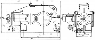
The assembly diagram is indicated in the drawing below and is described in detail in the technological documentation, which is issued to production along with the drawings. On the main drawing with a general view, the table indicates the technical characteristics of the gearbox, which are then transferred to the passport:
- number of steps;
- gear ratio;
- number of revolutions of the drive shaft;
- output power;
- efficiency;
- dimensions;
- weight.
Additionally, the vertical location of the gearing, the direction of shaft rotation and the installation method: flanged or foot-mounted can be indicated.
Types of gears
To transmit rotational motion, gearboxes use gears that form gears that transmit motion to shafts.
Gear transmissions are -
- cylindrical (rotational motion with parallel axes, a)
- conical (rotational movement with intersecting axes b)
- worm and hypoid - (with crossing axes, c)
Gears are available with external and internal gearing. Worm gears are made as solid cast, or forged, or composite. The degree of accuracy of gears and gears is determined by their design, purpose, speed and operating conditions of the mechanisms. A gear with a small number of teeth is usually called a pinion, and a gear with frequent teeth is called a wheel.
