A well is drilled using a drilling rig, which is a complex of units, mechanisms and structures located on the surface.
drilling kit includes: a tower for hanging the traveling system and placing drill pipes, equipment for lowering and lifting tools, equipment for feeding and rotating tools, pumps for pumping drilling fluid, power drive, mechanisms for preparing and cleaning drilling fluid, mechanisms for automation and mechanization of hoisting operations, instrumentation and auxiliary devices. The drilling rig also includes metal bases on which the equipment .
drilling conditions and purposes in the presence of a wide variety of well design depths cannot be satisfied by one standard size of drilling rig, therefore GOST provides for a number of drilling rigs. Drilling rigs are classified according to their permissible hook load.
The standard also provides for a number of other parameters of drilling rigs, including the drive power of the main mechanisms, the nominal lengths of the candles, the elevations of the bases and some other indicators.
The drilling rig for drilling a specific well or group of wells is selected according to the permissible load on the hook, which should not exceed the weight (in air) of the heaviest casing string.
DRILLING RIG AND FOUNDATION
The drilling derrick is designed to raise and lower the drill string and casing into the well, hold the drill string suspended during drilling, as well as to accommodate the traveling system, drill pipes and part of the equipment necessary for the drilling .
Drilling derricks vary in lifting capacity, height and design. To drill wells up to 4000 m, towers with a height of 41 m are used, for wells with a depth of more than 4000 m, towers with a height of 53 m or more (60-70 m) are used.
Based on their design, towers are divided into two types: tower and mast. Tower towers are those towers in which the load is transferred to four supports. In mast-type towers, the load is transferred to one or two supports.
In domestic drilling, 41-meter tower-type derricks are widely used. This is a tetrahedral truncated pyramid consisting of 10 panels, each 4 m high. The lower base of the tower has dimensions of 8×8 m, and the upper one is 2×2 m. The legs of the tower in the lower part have support plates, using these plates the tower is attached to the foundation with bolts. Special tables are welded to the upper ends of the legs for installing and fastening the crown block beams on which the crown block is installed. Depending on the length of the candles used, a balcony (polati) is installed around the tower. During lowering and ascent operations, a horse worker (assistant driller ) works on the balcony. He installs the candles lifted from the wells by the finger or feeds them from behind the finger when lowering into the well. When using a 41-meter tower, the balcony is installed at a height of 22.5 m from the floor, since they are drilling using 24-25 m candles.
Mast-type towers (A-shaped towers) are widely used. A-shaped sectional mast-type towers are an A-shaped metal structure consisting of two-, three- or tetrahedral legs and two struts. At the top, the legs are connected to each other by a sub-crown block frame on which the crown block is mounted. At the bottom, the legs of the tower are attached to the supports of the tower base. To protect against accidental falling of drill pipe candles, safety belts are installed on the tower. A-type derricks have a number of advantages compared to tower-type derricks: less metal is spent on their production, they have fewer parts, their installation and dismantling is easier, working conditions for dragging pipes into the drilling rig and throwing them onto walkways from the drilling rig , as well as visibility in the drilling rig .
Simultaneously with the installation of the drilling rig, the construction of additional structures is underway. The usual structures include the following.
1. Gearbox (aggregate) shed designed to shelter the engines and transmission mechanisms of the winch. It is attached to the tower lantern from its rear panel in the direction opposite to the walkway. The dimensions of the gear shed are determined by the type of installation.
2. Pump shed for housing and covering mud pumps and power equipment . The pump shed is built either as an extension to the side of the lantern of the gear shed tower, or to the side of the tower. In the first case, the dimensions of the barn are 5x15 m, in the second - 9x14 m, the height of the barn is 4.5-5 m.
Depending on the specific conditions, the walls and roof of the gear and pump sheds are sheathed with boards, corrugated iron, reed panels, rubber fabrics or polyethylene film.
The use of some drilling rigs requires a combination of gear and pump sheds.
3. Reception bridge, designed for laying drilling equipment , tools, materials and spare parts along it Reception bridges can be horizontal or inclined. The installation height of the receiving bridges is adjusted by the installation height of the drilling rig frame. The width of the receiving bridges is up to 1.5-2 m, length up to 18 m.
4. A system of devices for cleaning the flushing solution from drilled rock, as well as warehouses for chemical reagents and bulk materials.
5. A number of auxiliary structures: when drilling with an electric drive - transformer sites, when drilling with an internal combustion engine - sites on which containers for fuels and lubricants are located, etc.
6. Social and cultural facilities: cultural booth, canteen, dormitory cars, etc.
Drill drawworks: purpose and parameters, classification, kinematics and dynamics
Drilling drawworks are the main mechanism of a drilling rig; it is designed to carry out the following operations:
lowering and raising drilling and casing pipes;
holding the column suspended;
transmission of rotation to the rotor;
making up and unscrewing pipes;
carrying out auxiliary work on hauling to the drilling rig
tools, equipment, pipes, etc.;
to lift the assembled tower into a vertical position.
Code: U2-5-5;
where U - ; 2 — unit number at the drilling rig; 5 — number of winch speeds; 5 is the model number.
U2-300; where 300 is the nominal load capacity, tons
LBU-1100M1
where LB is the drawworks; U - ; 1100 - power created by the lifting shaft, kW M1 - water cooling of the brakes is not used (M2 is used, D is for working with a diesel drive, E is with an electric drive).
LB-75-Br - marking of Volgograd winches.
The speed of lowering the columns is determined by their weight, length and technological conditions of the well. The highest lowering speed is 3 m/s, the lowest when lowering casing strings is 0.2 m/s. During the drilling process, the feed of the drilling tool should not exceed 1.5 m/min.
Main parameters:
1) drive power on the winch drum:
;
where is the weight of the hook; weight of suspended equipment; hook speed; efficiency traveling system.
2) torque on the lift shaft:
; ;
where is the tension of the running end; efficiency winch drum; coefficient taking into account inertial forces during descent;
pulley multiplicity (number of working strings); maximum winding diameter.
3) Maximum ascent speed
Vx = Vcr * iTS
where Vcr – hook lifting speed; iTS – equipment multiplicity.
At iTC ≤ 10, Vcr = 2 m/s
iTC ≥ 10, Vcr = 20/ iTC.
4) The diameter of the winch drum is selected depending on the diameter of the traveling rope Db = (23 – 26) * dK
Kinematics of the lifting mechanism
In the first period, the winch drum accelerates, which is why the acceleration of the hook movement and V (from 0 to the initially established VLL) is equal to the acceleration. To reduce dynamic loads, acceleration during acceleration should be minimal. With linear increase;
A1-acceleration of the hook during acceleration; t1-acceleration duration; H1 - hook path during acceleration; γ is the slope of the V curve.
2nd period - steady motion, in which the engine and winch drum rotate at a constant frequency
DT is the diameter of the rope winding on the drum; ITP and ITC are transmission and tackle system gear ratios.
Due to the summation of the winding diameter of the traveling rope, the horizontal section of the tachogram takes on a stepped appearance. In kinematic calculations using the average steady-state V of the lift:
Where VKU is the final steady V of the hook lift. Based on the average steady V, for the rise period we have: A2=0; VCU=const; HI=VSU∙t2/
In the 3rd period, the drawworks is braked, during which the final steady-state V of the lift is reduced to 0. A3=const; VKU=A3∙t3; H3=A3∙t3/2.
where A3 is the deceleration of the hook when braking; VKU-V hook at the beginning of braking.
DRILLING WINCHES
A drawworks is used for lowering and lifting a drill string, lowering casing strings, holding a stationary drill string suspended or slowly lowering it (feeding) during the drilling . In addition, in some cases, a drill drawworks is used to transmit power from the engine to the rotor, screwing and unscrewing pipes, hauling loads and other auxiliary work. The winch is one of the main units of the drilling rig.
When lifting the hook, power is supplied to the winch from the engines, and when lowering, on the contrary, the braking devices must convert all the released energy into heat.
The drawworks consists of a welded frame on which lifting and transmission (one or two) shafts, belt and hydraulic or electric brakes and a control panel are mounted on rolling bearings. In addition, some winches are equipped with gearboxes that reduce the number of winch shafts.
Drilling drawworks are equipped with two types of brakes: band and hydraulic or electric. Band brakes are used to hold the pipe string suspended, regulate the descent speed and complete braking at the end of the descent, as well as to feed the bit during the drilling , if drilling without an automatic feeder. Drilling drawworks are usually equipped with two-band brakes with manual and pneumatic control
Drawworks. Purpose, design and classification.
The drawworks is the main mechanism of the drilling rig and is designed to perform the following operations:
Ø lowering and raising drilling and casing pipes;
Ø holding the pipe string suspended during the process of drilling or flushing a well;
Ø transmission of rotation to the rotor;
Ø screwing and unscrewing pipes;
Ø carrying out auxiliary work on hauling tools, equipment, pipes, etc. into the drilling rig;
Ø for lifting the assembled tower into a vertical position.
Drilling drawworks differ in power and other technical parameters, as well as in kinematic and design features.
Power of drilling drawworks,
regulated for domestic winches by GOST 16293-82, is in the range of 200-2950 kW depending on drilling depths.
According to the number of ascent speeds
There are two-, three-, four- and six-speed drawworks. Eight- and ten-speed drawworks are used abroad. Lifting speeds are changed by shifting gears between winch shafts or through a separate gearbox.
Depending on the drive used
There are drilling drawworks with stepped, continuous-step and stepless changes in lifting speeds. A stepwise change in lifting speeds is available in drilling drawworks with mechanical transmissions from heat engines and AC electric motors. With hydromechanical transmissions, winches with the same engines have a continuous step change in the lifting speed. In the case of using a drive from DC electric motors, the hoisting speed of the winch changes steplessly along the constant motor power curve.
According to the scheme for switching on high-speed gear
There are drawworks with independent and dependent “fast” speed. As is known, when lowering drill pipes and casing, two speeds are used in accordance with the sequence of operations performed: quiet - for lifting the pipe string in order to free the wedges or elevator and fast - for subsequent lifting of the unloaded elevator behind the next stand. To speed up the descent, switching the indicated speeds should not take much time and is therefore carried out by friction clutches from the driller's station. Drawworks with an independent speed pattern allow the unloaded elevator to be lifted at a fast speed, regardless of the slow speed used for lifting. With a dependent scheme, an unloaded elevator is raised at different speeds, equal to or proportional to the speed used to lift the pipe string.
By number of shafts
There are one-, two- and three-shaft winches. Single- and double-shaft winches are equipped with a separate gearbox. In three-shaft winches, lifting speeds are changed using gears installed between the shafts of the winch itself. For auxiliary work, two- and three-room winches are equipped with a friction reel. If a single-shaft winch is used, an additional auxiliary winch is connected for this purpose.
Drilling drawworks differ in the number of speeds transmitted to the rotor and the kinematic transmission scheme,
installed between the winch and the rotor.
According to the method of bit feed control
There are drawworks with manual and automatic control, carried out by means of a bit feed regulator.
By design, drilling drawworks are divided into two groups:
Two or three shafts (U2-5-5 and U2-2-11).
Explanation of symbols:
§ U – Uralmash plant; the first digit is the unit number;
§ the second digit is the number of winch speeds (for U2-5, taking into account the speeds of the gearbox, and for U2-2, taking into account only the speeds of the winch without the gearbox);
§ The third digit is the model number in chronological design order.
Single-shaft with variable gearbox (LBU-750, LBU-1100, LBU-1700). Explanation of designations: LB – drilling winch; U – Uralmash plant; 750, 1100, 1700 – drum power in horsepower.
Drilling winches of the first group consist of a welded frame on which a rolling bearing, a lifting shaft with a drum for winding the traveling rope, intermediate and transmission shafts are mounted. All shafts are kinematically connected to each other by chain transmissions, which transmit torques to them and are used to regulate the rotation speed of the shafts. On the intermediate shaft, in addition to the chain drive sprockets, in some cases special coils are installed for carrying out work on pulling loads, screwing and unscrewing pipes, and during hoisting operations. Such shafts are called reel shafts. In single- and double-shaft winches, reels are not installed, and auxiliary winches and pneumatic releasers are used to carry out work on pulling loads and screwing together pipes. The winch frame is covered with safety shields.
The lifting shaft of the winch is equipped with two types of brakes - belt with manual and pneumatic control (located on the brake pulleys of the winch drum) and hydraulic or electric (connected through a coupling to the lifting shaft).
Band brakes are used to hold the pipe string suspended, regulate the descent speed and complete braking, and also to feed the bit to the bottom when drilling wells. Hydraulic or electric brakes are needed to slow down the descent of the string and facilitate operation of the band brake.
To ensure uniform delivery of the bit to the bottom, all modern winch designs are equipped with ADF automatic feeders or RPD bit feeder regulators, which are connected by chain transmissions to the lifting shaft and are engaged with chain cam clutches during drilling. The winches are equipped with a special transmission for rotating the rotor.
In winches LBU-1100, LBU-1700, LBU-3000, included in the sets of drilling rigs BU-5000, BU-6500, BU-8000 with electric drive, there is no rotor transmission, and the rotor is driven by a separate electric motor.
Rice. 18. Drawworks LBU-750
The single-shaft winch LB-750 consists of: a frame on which a lifting drum shaft with brake pulleys, tire-pneumatic friction clutches and a cam clutch, as well as chain sprockets is mounted on two brackets in bearings. The frame also contains a winch control panel, an intermediate rotor drive shaft and an auxiliary brake.
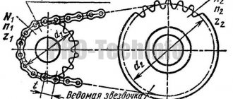
Rice. 19. Schematic diagram of a three-shaft winch:
1
- main drum;
2
— mechanical brake (main);
3 — friction clutch of slow rotation; 4 —
swivel for supplying water and air;
5
— hairpin coil;
6 —
slow rotation gear;
7 — transmission shaft; 8
— transmission of the reel shaft drive;
9
— clutch for turning on the reel shaft;
10 —
transmission of the high-speed rotation drive;
11 —
reel for releasing locks;
12
— friction clutch for enabling rapid rotation;
13
— auxiliary brake clutch;
— auxiliary brake; 15
— swivel for air supply and water drainage;
16 —
rotor drive transmission;
17
— mechanical brake balancer;
18
— brake crankshaft;
19
— brake band;
20 —
brake lever;
2.1 -
pneumatic braking cylinder.
TRAFFIC SYSTEM
The pulley (pulley) system of drilling rigs is designed to convert the rotational movement of the winch drum into translational (vertical) movement of the hook and reduce the load on the rope branches
A steel traveling rope is passed through the rope pulleys of the crown block and the traveling block in a certain order, one end of which is fixedly attached. The other end, called the running (driving) end, is attached to the winch drum.
The crown block is a frame on which axles and supports with pulleys are mounted. Sometimes the frame is made integral with the top of the tower.
Travel system equipment. As the well deepens, the weight of the load that has to be lifted or lowered continuously increases. Since the engine for the winch is selected based on the conditions for lifting or lowering a load of maximum weight, it is quite obvious that it is used ineffectively during the process of drilling a well. Its full power is used only when the well's design depth is reached, and then only when the first candles are lifted. Therefore, they strive to select a pulley mechanism that would require less power. This is achieved by using various equipment of the traveling system: 2×3; 3x4; 5x6; 6x7.
Drilling hooks and hook blocks. Drilling hooks are manufactured in the form of separate hooks or hooks connected to a traveling block (hook blocks). drill strings using slings with an elevator during tripping and ascent operations, during the drilling process for suspending a swivel with a drill string, as well as for lifting, lowering and pulling loads during drilling and installation and dismantling operations.
By design, hooks come in one-, two- and three-horned types. Currently, three-horned hooks have almost completely replaced two-horned and one-horned hooks. The presence of three horns allows the slings, suspended on the side horns of the hooks at the beginning of drilling , not to be removed until the end of drilling the well, as a result of which the work of the drilling crew is facilitated and the time spent on auxiliary operations is reduced.
According to the manufacturing method, hooks are forged, composite, plate and cast.
Design features and advantages of ET series drawworks
- The gear transmission allows you to get “quiet” and “fast” speeds on the lifting shaft. “Fast” speed is for raising and lowering the drill string and an empty elevator, “quiet” speed is intended for working with casing and eliminating accidents.
- multifunctional drive: the winch drive electric motor provides not only lifting, but also controlled lowering of drilling and casing strings and an empty elevator until it comes to a complete stop and is kept stationary; adjustable bit feed to the bottom in the bit feed regulator mode; in case of failures in the main power supply network, the engine is capable of lifting drill pipes, operating from a 200 kW diesel power plant.
- The disc brake includes 2 discs, 2 drive systems - working and emergency. A brake driven by a working cylinder is used to keep the machine stationary. Wear on pads and discs is virtually eliminated.
- drum: the drum is cut and the flanges are protected with ring linings made of wear-resistant steel.
- non-contact seals: a special sealed design not only prevents oil from leaking out, but also the penetration of dust and moisture into the transmission housing; There are no wearing parts such as cuffs in the seal.
- remote control creates comfortable working conditions. All control practically comes down to controlling the handle of the engine control system command apparatus. The driller can work in a sitting position.
EQUIPMENT FOR MECHANIZATION AND AUTOMATION OF SPO
To carry out tripping operations, the drilling crew must be equipped, firstly, with tools for gripping and hanging a pipe string (elevators, wedge grips, etc.) and, secondly, with tools for making up and unscrewing drill and casing pipes ( machine keys, round keys, etc.).
Tool for gripping and hanging pipe strings. Elevators, wedges and spiders (elevators with ram grippers) are used as such tools. Devices for gripping and hanging columns vary in size and load capacity.
Tools for making up and breaking out drill pipes and casing.
Various keys are used as such a tool. Some of them are intended for make-up, and others for fastening and loosening threaded connections of a column. Typically, light circular wrenches for pre-make-up are designed for locks of the same diameter, and heavy machine wrenches for fastening and loosening threaded connections for two, and sometimes more, sizes of drill pipes and castles.
Mechanical wrenches for screwing and fastening pipes. In order to facilitate labor and speed up the process of descent and ascent, the following are widely used:
1. Stationary automatic wrenches of the battery type, which fully mechanize all screwing and unscrewing operations, including fastening and loosening threaded connections, as well as auxiliary operations (approach and removal of the wrench, grasping and releasing the pipe), which allows speeding up these works by 8-10% . Automatic universal wrenches are produced, including those for screwing and fastening casing pipes - AKBU. Automatic keys must be equipped with a torque meter;
2. Suspended pneumatic tongs of the PBK type, mechanizing the main operations of making up drill pipes. The use of PBK type wrenches speeds up this work by 3-5%.
The main direction of automation of hoisting operations at present is equipping drilling rigs with means of mechanization and control of hoisting in an optimal mode. Optimization of tripping operations means the minimum costs of tripping and recovery, taking into account the limitations of well drilling technology.
Based on the creation of a number of mechanisms for the automation and mechanization of individual operations of lowering and hoisting work, an automatic lowering and hoisting (ASP) has been created in our country. This installation allows for comprehensive mechanization of hoisting operations. The complex of ASP mechanisms provides:
1. time combination of lowering and raising the drill pipe string and an unloaded elevator with the operations of making up and unscrewing the candles, installing them on the candle holder and moving them to the center of the well;
2. mechanization of screwing and unscrewing of spark plug connections;
3. automation of the capture and release of the drill pipe string by an elevator;
4. mechanization of installation of candles on a candlestick and their removal to the center of the well;
5. mechanization of lubrication of threaded connections of spark plugs.
The combination of operations is achieved by introducing into the installation kit a special traveling system and mechanisms for arranging candles. In the presence of these mechanisms, the drilling drawworks only raises and lowers the pipe string and the empty elevator; all operations with the unscrewed candle are performed by mechanisms for their placement. This allows you to significantly reduce the time for hoisting operations.
The structure of a drill drawworks and the principle of its operation
| Random page | VOLUME-1 | VOLUME-2 | TOM-3 Cars | Astronomy | Biology | Geography | A house and a garden | Other languages | Other | Computer science |
| Story | Culture | Literature | Logics | Mathematics | Medicine | Metallurgy | Mechanics |
| Education | Occupational Safety and Health | Pedagogy | Policy | Right | Psychology | Religion | Rhetoric |
| Sociology | Sport | Construction | Technology | Tourism | Physics | Philosophy | Finance |
| Chemistry | Drawing | Ecology | Economy | Electronics |
DRILLING PUMPS
Mud pumps are designed to supply drilling fluid under pressure into a well. Only horizontal, drive, piston pumps are used for drilling. Two- and three-cylinder mud pumps are used.
The discharge pipeline is designed to supply drilling fluid from the pump to the pressure drilling hose. The discharge pipeline consists of horizontal and vertical (riser) sections. On the horizontal section of the pipeline, pipes are installed for connecting to pumps, pipes for piping blowout prevention equipment , main and starting valves and a pipe for a pressure gauge. The horizontal section of the pipeline is sloped towards the pumps to ensure the flow of drilling fluid through the starting valve, which is installed at the lowest point of the pipeline.
The riser - a vertical section of the pipeline - in the upper part has a neck with a flange for connecting a drilling hose, and in the lower part there is a pipe with a valve for connecting flushing units and a pipe for a pressure gauge.
During the operation of mud pumps, a pressure exceeding the permissible level may be created in the discharge pipeline. This can lead to rupture of the pressure line and the pump itself and injury to operating personnel.
To prevent accidents of this kind, a special device is mounted on each mud pump, into which a fuse is inserted - a plate calibrated for a certain pressure. This device is connected to a drain pipe, through which, when the safety plate ruptures, the drilling fluid is discharged into a receiving tank.
POWER EQUIPMENT
A power drive is understood as a complex device that converts electrical energy or fuel energy into mechanical energy and provides control of the converted mechanical energy.
The main elements of the power drive are the engine, transmission devices (mechanisms) from it to the actuator and control system devices.
The drive of the main actuators drilling rig (drawworks, mud pumps, rotor) is called the main drive. Depending on the type of engine and type of transmission, it can be electric, diesel, diesel-hydraulic, diesel-electric and gas turbine . The most widely used in modern drilling rigs are electric, diesel, diesel-hydraulic, and diesel-electric drives.
The main advantages of an AC electric drive are its relative ease of installation and operation , high reliability, and efficiency. At the same time, drilling rigs with this type of drive can only be used in electrified areas.
The diesel drive is used in areas that are not provided with electricity of the required power. The main disadvantage of internal combustion engines is the lack of reverse, so a special device is needed to obtain reverse motion. Diesel internal combustion engines allow overload of no more than 20%.
The diesel-hydraulic drive consists of an internal combustion engine and a turbo transmission. A turbo transmission is an intermediate mechanism usually built between the diesel engine and the transmission. The use of turbo transmission ensures: smooth lifting of the load on the hook; engine operation if the load on the hook is greater than that which the internal combustion engine can overcome, in this case the engine will operate at reduced but quite stable rotation speeds; greater transmission durability.
The greatest advantage is the drive from DC electric motors, the design of which does not include bulky gearboxes, complex connecting parts, etc. The DC electric drive has convenient control and can smoothly change the operating mode of the winch or rotor over a wide range.
The diesel-electric drive consists of a drive motor coupled to an actuator; a generator that powers this electric motor; diesel engine that drives the generator, diesel fuel is also required, delivery!
Drilling development method, page 31
Technological reasons: incorrect ratio of drill collar and well diameters; loss of stability of the lower part of the drill string; incorrect choice of number, installation locations and design of devices centering the lower part of the drill string in the well; the use of a drilling mode whose parameters do not correspond to the design of the lower part of the drill string and the geological conditions of the occurrence of passable rocks.
As a result of the curvature of the wellbore, drill pipes, locks, and couplings wear out more intensively; tripping operations are complicated due to tightening of the drill string; guttering and rockfalls are likely; additional power is consumed to rotate the drill string; it becomes difficult to lower the casing into the well; the likelihood of collapse of casing pipes in places of sharp curvature of the trunk increases; cementing of casing strings is complicated (due to the pressing of the string to one side of the wellbore), uniform filling of the annulus with cement mortar; The volume of inclinometric measurements increases and their implementation becomes more difficult.
The curvature of the well affects its operation.
1.11.DRILLING WINCHES
The winch is the main mechanism of the drilling rig. It is designed to carry out the following operations:
lowering and raising drilling and casing pipes;
holding a pipe string suspended during the process of drilling or flushing a well;
transmission of rotation to the rotor;
making up and unscrewing pipes;
auxiliary work for hauling tools, equipment, pipes, etc. into the drilling rig;
lifting the assembled tower into a vertical position.
The drawworks includes a welded frame on which the lifting, transmission and intermediate shafts, gearbox (Gearbox), brake system consisting of the main (band) and auxiliary (regulating) brakes, and control panel are located. All mechanisms are covered with safety shields.
The lifting shaft of the winch converts the rotational motion of the power drive into the translational motion of the hoist rope. To lift a loaded hook, power is expended, depending on the gravity of the pipes being lifted, and the hook is lowered under the influence of the weight of the pipes. Therefore, winches have mechanisms for supplying power during lifting and braking devices. To increase the speed when lifting the hook, winches or their drives are multi-speed. Switching from high speed to low speed and back is carried out by frictional operational clutches, ensuring smooth activation and minimal time spent on these operations. The power transmitted to the winch characterizes its main operational and technical properties and is its main parameter.
Modern domestically produced drilling drawworks are made mainly according to two layout schemes:
the winch with all components is mounted on one common frame and represents one unit (for example, U2-2-11, LB-750);
a winch consisting of two separately transportable units (lifting and gearbox), which are connected to each other using ties (for example, LBU-1100, LBU-1400).
In the U2-5-5 winch, the lifting unit is connected to the gearbox by two powerful cardan shafts on the side opposite the driller's console.
Recently, drilling rigs have been produced in which the main winch is located below the drilling rig floor, and auxiliary winches are used to perform auxiliary operations (unfastening pipes, hauling small loads, etc.). At the same time, the design of the main winch is simplified and its weight is correspondingly reduced.
Drawworks components
bed
It is a welded metal frame on which the winch units are mounted. The frame protects individual parts of the winch from damage and loss during transportation, and also gives the winch rigidity and strength.
EQUIPMENT FOR PREPARATION, CLEANING AND PROCESSING OF DRILLING FLUIDS
Preparation of drilling fluids can be carried out in mechanical mixers and hydraulic mixers.
Currently, in domestic practice, powdered materials are widely used for the preparation of drilling fluids. To prepare drilling fluids from these materials, the following equipment : a solution preparation unit (BPR), an external hydraulic ejector. mixer, hydraulic disperser, CS tanks, mechanical and hydraulic mixers, piston pump.
The BPR is a single transportable unit, on the frame of which two cylindrical telescopic containers are mounted, consisting of a common lower base on which the stationary parts of the container are installed, and an upper movable part. Both parts of the container are connected to each other by a rubber-fabric seal.
In a number of cases, drilling fluid is prepared using a mechanical mixer (clay mixer). In mechanical clay mixers you can prepare solutions from raw clays, clay briquettes and clay powders.
Milling-jet mills are more efficient than clay mixers. The milling-jet mill is a metal container divided by a partition into two parts: a receiving hopper and a throwing chamber with a bladed rotor. The lump clay is loaded into a hopper where water is supplied. The blade rotor crushes and throws the clay along with water onto a dispersing corrugated plate, where intensive dispersion of the clay occurs.
Cleaning the flushing fluid from drilled rock debris (sludge). The drilling fluid that comes to the surface from the well can be reused, but for this it must be cleaned of drill cuttings (sludge).
To clean drilling mud from cuttings, a complex of various mechanical devices is used: vibrating sieves, hydrocyclone sludge separators (sand and oil separators), separators, centrifuges. As part of the circulation system, all these mechanical devices must be installed in strict sequence. In this case, the flow diagram of the drilling fluid must correspond to the following technological chain: well - gas separator - block for coarse cleaning from sludge (vibrating screens) - degasser - block for fine cleaning from sludge (sand and silt separators, separator) - block for regulating the content and composition of the solid phase ( centrifuge, hydrocyclone clay separator) - mud pumps - well.
For the purification of drilling fluids, a three-stage system has been adopted as mandatory.
Vibrating screens. Cleaning drilling fluid from cuttings using vibratory sieve-mechanical process in which particles are separated using a screening device.
Hydrocyclone sludge separators. The drilling fluid is pumped into the hydrocyclone. Under the influence of centrifugal forces, heavier particles are thrown to the periphery and descend down the cone of the hydrocyclone and merge outward. Clean drilling fluid is concentrated in the central part of the hydrocyclone and discharged into the receiving tank.
SMALL MECHANIZATION
Small mechanization includes machine keys, elevators, chisel turning boards, hooks (for supplying and discharging pipes).
The elevator is used to capture and hold a string of drilling (casing) pipes suspended during tripping and other work at the drilling rig. Elevators of various types are used, differing in size depending on the diameter of drilling or casing pipes, load capacity, design and material for their manufacture.
The elevator is suspended from a lifting hook using slings.
Drill wedges are used to suspend the drilling tool in the rotor table. They are inserted into the tapered hole between the pipe and the rotor liners. The use of wedges speeds up work on hoisting operations. Recently, automatic wedge grips with a pneumatic drive - PKR - have been widely used (in this case, the wedges are inserted into the rotor not manually, but using a special drive, the control of which is carried out on the driller's console).
Wedges for casing pipes (elevators with ram grips). To lower heavy casing strings, wedges with a one-piece body are used. The wedges are installed on special supports above the wellhead. The wedge consists of a massive body that takes the weight of the casing pipes.
Car keys. The operation of fastening and unfastening the threaded connections of drill strings and casing is carried out by two machine keys, with one key (holding) being stationary, and the second (screwing) being movable.
Drilling drawworks series ET
Drilling winches of the ET series are an original development, representing a range of sizes of winches with a lifting capacity from 125 to 500 tons, ensuring effective work in carrying out hoisting operations and drilling.
ET series winches have a unified kinematic diagram and design and are equipped with a DC electric drive operating according to the “thyristor converter-motor” circuit.
The winches are simple in design, compact and their weight is less than winches with a chain transmission.
The unique design of the ET series winches makes it possible to abandon traditional structural elements: chain transmission, tire-pneumatic clutches, electromagnetic or hydrodynamic brakes, band brakes and brake control handles.
INSTRUMENTATION AND CONTROL INSTRUMENTS
Instrumentation includes: pressure gauges (MBG-1), hydraulic and electrical weight indicators (GIV-6 and MKN-1), sensor for measuring rotor torque (DKM), level gauge (UP-11M), tachometers (used to determine frequency rotation of the power drive), flow meters (RGR-7), instruments for determining the properties of the flushing liquid.
Bottom load is defined as the difference between the weight of the drill string when the tool is slightly raised above the bottom and its weight while drilling . The weight of the drill string is measured by a weight indicator based on the tension of the fixed end of the hoist rope.
Hydraulic and electrical weight indicators have been developed and are being used in practice.
Hydraulic indicators are available for measurement limits of 40-80 kN, 120-180 kN and 200-250 kN. Pressure transformers are calibrated with ropes of a certain diameter. The main given error is ±2.5%.
Hydraulic weight indicators are simple in design and easy to operate, but do not allow for remote measurements and recording of parameters, and the tightness of the measuring systems is often broken.
Electrical weight indicators also measure the weight the drilling tool and downhole pressure based on the load at the dead end of the wireline. They consist of a sensor with a converter and a secondary device.
The load measurement limit with an electric weight indicator is up to 250 kN, the measurement error is 2.5%.
The torque on the rotary table is controlled by the force transmitted by the rotor to the sub-rotor base. Torque is measured regardless of the direction of rotation of the rotor and the tension of the chain drive. The torque of the rotary table, which causes the pipe string with the tool to rotate, is measured by the change in the tension of the chain drive with a DKM sensor, which is installed under the drive branch.
I view the rotary table drive chain. One of the most important parameters of the well flushing regime is the drilling fluid flow rate. Various devices have been developed to measure flow. In practice, the most widely used induction flow meter is RGR-7, the operating principle of which is based on the law of electromagnetic induction.
Controlling drilling fluid pressure is essential. Studying the pressure in the injection system of rig allows one to judge the operation of the pumps and the entire circulation system, the efficiency of well flushing, and indicates possible complications.
To control the drilling fluid pressure at the pump outlet, mechanical and electrical pressure gauges are used. The most widely used drilling manometer is drilling pressure MBG-1, the operating principle of which is based on the conversion of the measured pressure into the angle of rotation of a non-contact synchro-sensor with subsequent remote transmission of readings.
To continuously measure the level of drilling fluid in the receiving tank of drilling pumps and issue light and sound alarm signals when the level deviates from the set level, use the UP-11M level gauge, consisting of two level sensors (float type), a switch, a recorder, and a signal siren. The device can measure levels up to 0.9 m, the main reduced error of its measurement is ± 6%.
The most important parameters characterizing drilling fluid is density. The pressure on the formations that form the walls of the well, the transfer of energy from the pump to the downhole motor (turbo-drill), the erosion of rock at the bottom, etc. depend on the density.
Devices for measuring liquid density - density meters, based on their operating principle, are divided into gravitational (AVP-1), in which a certain volume of liquid is weighed; hydrostatic, measuring the pressure of a liquid column of constant height (these also include piezometric); float; radioactive (PZHR-5), based on the principle of absorption of radioactive radiation; resonant (vibration) ones, which use the frequency of natural vibrations of solid bodies in the medium under study. In gravity density meters, the sensing element is a chamber of constant volume through which the controlled fluid continuously flows. The increase in the mass of the sensitive element is proportional to the change in density.
The main characteristics of drilling fluids include rheological indicators (parameters): limiting static and dynamic shear stresses, effective and plastic viscosity.
At normal temperature, the limiting static shear stress is measured with the SNS-2 device, which consists of a measuring part and a drive mounted on a rectangular plate.
Rotational viscometers VSN-2 and VSN-3 are designed to measure the limiting static and dynamic shear stress and effective and plastic viscosity. VSN-2 is used to study the properties of drilling fluid at elevated temperatures (up to 200° C) and pressures (up to 15 MPa).
The VSN-3 rotational viscometer is designed to measure plastic viscosity, limiting dynamic and static shear stresses of drilling fluids at atmospheric pressure and temperatures up to 373o K. The device is used in field and laboratory conditions.
A high-temperature rheometer is used to study drilling fluids at high temperatures and pressures. The rheometer allows you to determine the maximum static shear stress in the range from 60 to 200 Pa. The maximum heating temperature of the test solution is 300° C, the maximum operating pressure is 15 MPa.
The intensity of fluid loss of drilling fluids and, consequently, crust formation determines the degree of change in the volume of rocks prone to swelling and narrowing of the trunk, the formation of screes, which can result in tightening and sticking of the drilling tool, a decrease in the reservoir properties of productive formations in the near-wellbore zone, leading to a decrease in their oil recovery , well cementing quality.
Various methods and devices have been developed for measuring water loss in static and dynamic modes. All devices include a container for drilling fluid and a filter and allow you to create pressure differences across the filter element.
To measure static fluid loss under normal conditions, use the VM-6 device. The UIV-2 type device is designed to measure the static fluid loss of drilling fluids at 250° C and pressure drops up to 5 MPa.
There are methods and devices for determining the total gas in drilling fluid and devices for determining the component composition of gas . The first group includes a method based on natural degassing of liquid with fivefold dilution with water, and devices VG-1, VG-2. VG-1 allows you to determine both the gas and fluid loss the drilling fluid.
The second group of devices includes semi-automatic devices for monitoring solution parameters, an automatic gas , an automatic device, and installations for gas-metric work when drilling a well.
Drilling rig equipment and units
Rigging and hoisting complex of the drilling rig
The functions of the hoisting complex are:
· lowering, raising and extension of drill pipes during drilling and auxiliary work;
· lowering and lifting operations with emergency and special tools;
· lowering of casing pipes.
· The hoisting and hoisting complex of the drilling rig includes a drilling drawworks and a traveling system.
Rice. 26.3. Simplified layout of hoisting equipment on a drilling rig:
1 – hook; 2 – traveling block; 3 – traveling rope; 4 – crown block; 5 – drilling rig; 6
– winch; 7 – mechanism for fastening the fixed branch. A – running end of the rope; - fixed end of the rope
The equipment of the lifting complex operates in the mode of repeated and short-term loads varying in magnitude. The process of lifting a column composed of candles from a well consists of cycles containing operations repeated in a strictly defined sequence:
— capture of the column by the elevator;
— lifting the entire column to the length of one stand with a load on the hook equal to the weight of the lifted column in the solution and the resistance forces during its movement in the well;
— installation of the column on the rotor table;
— release from the tensile load of a candle raised to the surface;
— unfastening with keys, unscrewing the raised candle from the column and installing it inside the drilling rig in a special store or laying it on a walkway near the drilling rig;
lowering the unloaded hook and elevator to capture the column suspended on the rotor;
- capturing and lifting the column to the length of the next candle, etc.
When lowering the column, these operations are performed in the reverse order, but with different durations and loads.
Drill drawworks
The drawworks is the main mechanism of the hoisting complex. With the help of a drill drawworks and a traveling mechanism, the drill string, casing pipes and other tools are lifted and suspended while drilling and casing wells. When lifting, the rotational motion imparted to the winch from the drive, using the traveling rope, is converted into the translational movement of the traveling block. When lowering, the brake devices of the drill drawworks limit the speed of descent of the traveling block, which is lowered under the influence of its own weight and the weight of the tool suspended from it. Drilling drawworks are also used to transmit rotation to the rotor, make-up and unscrew drill pipes and casing, and for lifting and hauling various loads during well drilling, installation and repair of installations.
According to their purpose, winches are divided into main and auxiliary.
The main winches perform the main function - carrying out hoisting operations with drilling and casing pipes. Auxiliary winches can also perform the functions of hauling loads, carrying out installation work, etc.
Winches are classified according to the following parameters:
¾ calculated power on the input shaft;
¾ load capacity (with the specified equipment of the tackle system);
¾ number of rotation speeds of the lifting shaft;
¾ lift shaft dimensions.
Rice. 8.6. Winch LBU37-1100-D-1
All winch components (Fig. 8.4) are installed on the frame (1). The winch includes a gearbox (7) with a gear shift mechanism (5). High-speed (11) and low-speed (14) gear blocks are installed to the right and left of the gearbox. The bearing housings of the low-speed bath contain an intermediate shaft (4), on which the drive sprocket of the low-speed transmission is installed. A mechanism for engaging the gear coupling (6) is installed on the frame. The bit feed regulator (2) is connected to the intermediate shaft via a gear coupling and an activation mechanism (3). The lifting shaft (12) is mounted on bearings, one of which is located in a low-speed bath, and the other on a separate support post. On the left side of the shaft there is a “quiet” speed sprocket and a dual tire-pneumatic coupling MSHU1070. On the right side there is a “fast” speed sprocket, a rotor transmission sprocket and an MSHU1070 clutch. A gear coupling cage is installed on the right side. By means of a gear coupling and an activation mechanism (10), the electromagnetic brake (9) is connected to the lifting shaft (12). Band brake assemblies (13) are installed on the winch frame complete with the lifting shaft. To ensure the necessary blocking when carrying out the trip and registering the bit feed, a command device with a depth sensor (15) is installed. An air duct (16) for pneumatic control of the winch is installed on the winch frame and a pump unit (8) for the lubrication system is mounted.
All rotating and moving elements of the winch are covered with guards. For inspection and access to chain drives, the baths are equipped with inspection “windows” and special hatches.
The bit feed regulator (RPD), in addition to the function of feeding the bit to the bottom during the drilling process, can provide lifting of the tool from the bottom of the well in the event of failure of the main drive, as well as raising and lowering the drilling derrick during installation and dismantling of the drilling rig. When the RPD is turned on, the kinematics of the winch allows for simultaneous transmission of rotor rotation from the main drive. The kinematic diagram of the winch is shown below (Fig. 8.5).
Rice. 8.5 Kinematic diagram of the LBU37-1100D-1 winch:
1 – lifting shaft (drum); 2 – tire-pneumatic coupling MSh1070x200; 3 – drive of the command device and feed sensor; 4 – electromagnetic brake TEI800-60; 5 – fast speed chain transmission; 6 – quiet speed chain transmission; 7 – bit feed regulator (RPDE); 8 – gearbox; 9 – gearbox (Ts2N-450-50-32-U2); 10 – shoe brake TKG400U2, 11 – electric motor 4PF-2B250
Brief characteristics of drilling drawworks are presented in Table 8.2.
Winches symbol: LBU37-1100D-1,
where LBU is the drilling winch of Uralmashplant; 37 – maximum rope tension on the drum, tf; 1100 – design power developed by the drive, kW; D – diesel drive; 1 – modification of the winch.
Table 8.2
Technical characteristics of winches
| Name of parameters | LBU-1200 | LBU-1200K | LBU22-720 | LBU37-1100D-1 | LBU1200D-1 | LBU-1200D-11 |
| 1 | 2 | 3 | 4 | 5 | 6 | 7 |
| Maximum load capacity, tf | 225 | 200 | 175 | 200 | 200 | 200 |
| 250 | 320 | 320 | ||||
| Estimated power at the input shaft, kW | 710 | 645 | 210 | 240 | 710 | 710 |
| Hoisting rope diameter, mm | 32 | 28 | 29 | 32 | 32 | 32 |
| Number of strings of the traveling system (equipment) | 10 12 (5x6) (6x7) | 10 (5x6) | 10 (5x6) | 10 (5x6) | 10 12 (5x6) (6x7) | 10 12 (5x6) (6x7) |
| Lift shaft rotation speed | 5 | 6 | 4 | 4 | 5 | 5 |
| Lifting drum dimensions, mm diameter | 800 | 650 | 635 | 685 | 800 | 800 |
| drum | 1300 | 840 | 840 | 840 | 1030 | 1030 |
| Brake system | Double band brake with counterbalancer | |||||
| Auxiliary brake | Hydrodynamic UTG-1450 | Electromagnetic TEP 4500 | Electromagnetic TEI 710 | Electromagnetic TEI 800 | Hydrodynamic UTG-1450 | Electromagnetic TEP-4500 |
| Brake pulley, mm Diameter | 1450 | 1180 | 1180 | 1270 | 1180 | 1180 |
| width | 250 | 250 | 250 | 250 | 250 | 250 |
| Additional drive | Additional drive | RPD** | RPD** | Additional drive | ||
| Chains | 2N-50.8 | 3N-50.8 | 3N-50.8 | 4N-50.8 | 2N-50.8 | 2N-50.8 |
| 2N-50.8 | 2N-50.8 | 2N-50.8 | ||||
| PR-12.7-1820-1 | PR-12.7-1820-1 | bN-38.1 | ||||
| PR-12.7-1820-1 | ||||||
| Couplings | 2MShU-1070 | 2MShU-1070 | 2MShU-1070 | 2MShU-1070 | 2MShU-1070 | 2MShU-1070 |
| MSh-700 | 2MSh-700 | 2MSh-700 | 2MSh-700 | |||
| 2MSh-500 | 2MSh-500 | gear | MSh-1700 | 2MSh-500 | 2MSh-500 | |
| Cam | Serrated | Serrated | Serrated | Serrated | ||
| Overall dimensions, mm | ||||||
| length | 7250 | 5750 | 6854 | 8333 | 7407 | 7430 |
| width | 3545 | 3181 | 3208 | 3227 | 2776 | 2903 |
| height | 2865 | 2598 | 2695 | 2208 | 2575 | 2420 |
| Weight, kg | 26548 | 23440 | 36400 | 40450 with TEI-800-60 | 23872 | 24450 with UTG-1450 |
*height without hydrodynamic brake tank;
** the additional drive is designed for raising and lowering the tower, lifting drill pipes and emergency work;
*** RPD function, except for those specified in the additional drive, regulation of the bit feed to the bottom.
Travel mechanism
The traveling mechanism or traveling system - the load-carrying part of the drilling rig - is a chain hoist consisting of a crown block and a traveling block, wrapped around a steel rope. The traveling block is equipped with a hook or automatic elevator for hanging the drill string and casing. The load of the suspended load is distributed between the working strings of the rope, the number of which is determined by the number of pulleys of the traveling block and crown block. The traveling system allows you to reduce the force in the rope from the weight of the load being lifted. Due to this, the length of the rope wound on the drum when lifting the load to a given height increases proportionally.
The equipment of the traveling system of drilling rigs (Fig. 8.6) is characterized by the fact that both ends of the traveling rope run down from the crown block, one of which is attached to the drawworks drum and is called running or traction, and the second (fixed) is to a special device on the metal base of the tower block . When winding the rope onto the drum, the traveling block with hooks is pulled to the stationary crown block. When lowering the traveling block, the rope is unwound from the drum, which rotates in the opposite direction under the influence of the weight of the traveling block, the hook and the suspended pipe string. The fixed string of the traveling rope is used to install special sensors that measure the load on the hook.
The working strings of the traveling rope are located between the pulleys of the crown block and the traveling block, and, unlike the running and fixed ones, they change their length when the hook is raised and lowered. The ratio of the number of working strings of the rope to the number of running strings going to the winch is called the rigging ratio
. Drilling drawworks are connected to the traveling block and crown block by one running string, and therefore the multiplicity of equipment in the traveling system of drilling rigs is equal to the number of working strings of the rope. Since the second end of the traveling rope is stationary and therefore non-working, the multiplicity of equipment for the traveling system of drilling rigs, regardless of the number of pulleys of the traveling block and crown block, is an even number equal to twice the number of pulleys of the traveling block.
In double-drum winches used for shallow exploration drilling, both ends of the rope are running. In this case, according to the number of running strings, the multiplicity of equipment is 2 times less than the number of working strings.
Rice. 8.6. Kinematic diagram of the lifting complex 1 – engine; 2 – transmission with gearbox; 3 – winch; 4 – crown block; 5 – traveling block; 6 – hook
Traveling mechanisms are mounted on the tower of drilling rigs and have the following characteristic features:
¾ a traveling block with a hook is located above the wellhead in a freely suspended state and moves in the vertical direction strictly along the axis of the well;
¾ the lifting height of the hook is limited by the height of the tower and the safety of lowering and lifting operations;
¾ the diameters of the pulleys and the dimensions of other load-carrying bodies are selected taking into account the transverse dimensions of the drilling rig;
¾ in order to control the current loads and maintain the specified axial load on the bit during the drilling process, the traveling mechanisms are equipped with sensors
¾ control and measuring instruments;
¾ The effective loads and speeds of tripping operations vary over a wide range depending on the depth of the well and the length of the pipe string.
Technical characteristics of equipment for traveling systems from various manufacturers are presented in Tables 8.3, 8.6.
Table 8.3
Technical characteristics of crown blocks for installations of OJSC "Uralmashplant"
| Index | Drilling rigs with manual placement of candles | |||
| UKB6-250 | UKB6-270 | UKB7-400 | UKB7-500 | |
| (3D86-1) | ||||
| 1 | 2 | 3 | 4 | 5 |
| Crown block diagram * | B | B | IN | A |
| Maximum | 2500 | 2700 | 4000 | 5000 |
| load, kN | ||||
| Number of cable cars | 6 | 6 | 7 | 8 |
| pulleys | ||||
| Rope diameter, | 28 | 32 | 32 | 35 |
| mm | ||||
| Outer | 1000 | 1120 | 1120 | 1400 |
| pulley diameter, mm | ||||
| Pulley diameter | 900 | 1000 | 1010 | 1285 |
| bottom of the groove, mm | ||||
| Axle diameter, mm | 220 | 220 | 260 | 280 |
| Bearings | 97744LM, | 42244, | 7097152M, | 7097556M, |
| pulley | conical | Roller | Conical | conical |
| two-row | cylindrical | two-row | two-row | |
| 220x340x100 | 220x400x65 | 260x400x104 | 280x420x1100 | |
| Dimensions, mm | ||||
| Length | 3180 | 2320 | 3230 | 6815 |
| Width | 2606 | 1440 | 3190 | 2440 |
| Height | 1335 | 1322 | 2440 | 2200 |
| Weight, kg | 3885 | 3430 | 6400 | 9515 |
Crown blocks have the following symbols: UKB 6-325,
where U is the designation of the manufacturer, Uralmashplant; KB – crown block; 325 – permissible load on crown block in vehicle
Table 8.4
Technical characteristics of crown blocks for VZBT installations
| Index | Crown block | ||||||||
| Sb.10A/BU2500 EU | B4.10.00.000 | B1.10.00.000 | B38.10.00.000 | M11.01.10.000 | |||||
| 1 | 2 | 3 | 4 | 5 | |||||
| Crown block diagram * | A | B | IN | IN | G | ||||
| Maximum load, kN | 1750 | 1000 | 1750 | 2000 | 1000 | ||||
| Number of rope pulleys | 5+1 | 5 | 5+1 | 5+1 | 5 | ||||
| Rope diameter, mm | 28 | 25 | 28 | 32 | 25 | ||||
| Pulley outer diameter, mm | 1000 | 900 | 1000 | 1000 | 760 | ||||
| Pulley diameter along the groove bottom, mm | 900 | 800 | 900 | 900 | 660 | ||||
| Axle diameter, mm | 170 | 170 | 170 | 170 | 170 | ||||
| Dimensions, mm | |||||||||
| Length | 2680 | 910 | 2120 | 816 | 1500 | ||||
| Width | 1046 | 950 | 910 | 1000 | 1000 | ||||
| height | 1400 | 950 | 1080 | 1080 | 1000 | ||||
| Weight, kg | 2260 | 1100 | 1470 | 2283 | 1180 | ||||
| Note. Pulley bearings – cylindrical roller bearing 42234 (GOST8328-75), 170x310x52 | |||||||||
*pulley layout diagrams
Table 8.5
Technical characteristics of hook blocks produced by OJSC "Uralmashzavod"
| Index | Hook block | ||||
| UTBK5- | UTBC 6- | UTBC 6- | UTBC 5- | UTBC 5- | |
| 225 | 320 | 450 | 225 | 320 | |
| (NBO- | (3D86-1, | ||||
| D,NBO-E) | 3 D86-2) | ||||
| 1 | 2 | 3 | 4 | 5 | |
| Maximum | 2250 | 3200 | 4500 | 2250 | 3200 |
| load, kN | |||||
| Number of cable cars | 5 | 6 | 6 | 5 | 5 |
| pulleys | |||||
| Rope diameter, | 32 | 32 | 35 | 28 | 35 |
| mm | |||||
| Outer | 1120 | 1120 | 1400 | 1000 | 1400 |
| pulley diameter, | |||||
| mm | |||||
| Pulley diameter | 1000 | 1010 | 1285 | 900 | 1285 |
| along the bottom of the groove, | |||||
| mm | |||||
| Axle diameter, mm | 220 | 260 | 280 | 220 | 280 |
| Execution | Lamellar | Cast | Plastincha | cast | |
| hook | ty | ||||
| Spring travel | 145 | 200 | 200 | 145 | 200 |
| hook, mm | |||||
| Bearing | 42244, | 7097152 | 7097556 | 97744LM, | 7097556M, |
| pulley | roller | M, | M, | conically | conically |
| th | conical | conical | th | th | |
| cylinders | th | th | two-row | two-row | |
| chesical | double-row | double-row | th | th | |
| 220x400x | th | th | 220x340x1 | 280x420x1 | |
| 65 | 260x400x | 280x420x | 00 | 100 | |
| 104 | 1100 | ||||
| Weight, kg | 6100 | 7520 | 8500 | 5320 | 7970 |
Hook blocks have the following symbols: UTBC 6-325,
where U is the designation of the manufacturer, “Uralmashplant”; TBK – hook block; 325 – permissible load on the crown block in tf.
Travel ropes
In accordance with GOST 16853-88, traveling ropes for production and deep exploration drilling are manufactured in three versions, differing in the type of cores used (Fig. 8.71) - with a metal core (m.s); with organic three-strand core (o.s); with a plastic rod core (i.s).
Hoisting ropes are manufactured with diameters of 25, 28, 32, 35, 38 mm in accordance with GOST 16853-88.
Rice. 8.7. Hoisting ropes type LK-RO with cores:
a – metal; b – organic three-strand; c – plastic
The magnitude of the breaking force of the rope is directly dependent on the size of the load being lifted, the equipment adopted and the required safety margin for the traveling rope established by the technical supervision authorities. To determine the breaking force of the traveling rope, you should be guided by the drilling rig's passport data, which indicates the nominal tension of the traveling rope on the winch drum.
Since the choice of traveling ropes for operating drilling rigs is largely determined by the diameters of the drilling rig's winding mechanisms, in order to obtain the required breaking force of the traveling rope, it is necessary to select a design that would ensure full use of the cross-section of the rope, as well as maximum temporary tensile strength of the traveling wires rope.
According to the permissible run-up of the tensile strength and plastic properties (the number of kinks and twisting until destruction), the wires of the hoisting ropes are divided into two grades - the highest B and the first I. The permissible run-up of the tensile strength of the wires taken from the rope should not exceed the values indicated below.
| Rope marking group by tensile strength, MPA | 1600 | 1700 | 1800 |
| Permissible run-up of tensile strength, MPa, rope, grade: B | 26 | 27 | 29 |
| 1 | 32 | 34 | 37 |
To maximize the use of the technical resource of hoisting ropes, it is advisable to select them with a five-fold safety margin of the total breaking force of the wires.
The durability of steel ropes significantly depends on the material and design of their core, which prevents the displacement of strands and crushing of the rope under the influence of axial and radial loads. Ropes with an organic core made of plant fibers (hemp, sisal, manila) are the most flexible. Ropes with plastic and metal cores have greater resistance to lateral compression, due to which they better retain their shape when going around pulleys and winding on a drum. Laboratory and field tests on drilling rigs have shown that the operating time of traveling ropes with a plastic core is 20–30% higher than the operating time of similar type ropes with a hemp core.
To protect against wear and atmospheric corrosion, the rope is coated with special lubricants during laying (technical petroleum jelly, bitumen in combination with tar, polyamide lubricants, etc.). Lubricants for traveling ropes, along with anti-corrosion and anti-friction properties, must have sufficient stickiness (adhesion) and temperature resistance.
Increased demands on the adhesive properties of lubricants are due to the action of significant centrifugal forces that throw the lubricant from the surface of the rope when bending around the pulleys and drum. The physical and mechanical properties of the lubricant must be maintained at temperatures from – 50 to + 50 ° C, characteristic of the northern and southern drilling areas. The lubricant is applied in a thin layer inside the strands and on the surface of the ropes during their manufacture. Organic rope cores are impregnated with anti-rot and anti-corrosion compounds.
Travel ropes are made by double laying wires into round strands, and the latter into single-layer six-strand ropes (cables). The six-strand design has a rational ratio of the diameters of the strands and the core, which provides an advantageous combination of strength and flexibility of the rope.
According to the laying method, cable construction ropes are divided into ordinary and non-unwinding. In ordinary ropes, the wires retain the stresses generated by their elastic deformation during the process of laying the strands and rope. Non-unwinding ropes are woven from pre-deformed wires and strands. As a result of preliminary deformation, the wires and strands acquire geometric shapes corresponding to their position in the finished rope. As a result, lay stresses are reduced, which helps reduce the elastic recoil moment of the rope and increase its flexibility and endurance.
a B C D
Rice. 8.8. Rope of double cross (a, b) and one-sided (c, d) lay: and c - right; b and d – left
As a result of comparative full-scale tests, it was established that the endurance of non-unwinding ropes is 25 - 30% greater than that of ropes with ordinary lay, therefore, hoisting ropes are made non-unwinding. The laying method is determined by the behavior of the wires and
strands in the finished rope. In an ordinary rope, when its ends are freed from bandages, the strands spontaneously unravel and require considerable effort to put them back together. Strands of non-unwinding ropes do not unravel and are easily laid back in their original position.
Depending on the relative position of the wires in the strands, ropes with point (TC) and linear (LC) contact (contact) of the wires are distinguished. Ropes with linear contact of wires are more durable. Tests show that their operating time is 1.5 - 2 times higher than the operating time of ropes with point contact. Hoisting ropes are of the LK-RO type, characterized by the fact that wires of different (P) and identical (O) diameters are used in individual layers of the strand. Thanks to the adopted design of the strands, sufficient flexibility and wear resistance of the traveling rope are provided, which are necessary for its effective operation.
Depending on the type of lay, there are different types of ropes: cross-lay and one-way lay (Fig. 8.8). In cross lay ropes, the wires in the strands are twisted in one direction, and the strands in the rope are twisted in the opposite direction. In single-sided (parallel) lay ropes, the wire and strands are twisted in one direction. With a cross lay, the outer wires are located parallel (Fig. 8.8, a and b), and with a one-side lay - at an angle to the axis of the rope (Fig. 8.8, b and d). Due to the flexibility and density of the wires across the cross-section, single-laid ropes have increased endurance and wear resistance. However, they are unsuitable for drilling rigs because they cause the free-hanging traveling block to twist due to excessive lay stresses in the rope wires. In cross lay ropes, the wires are deformed in different directions when laying the strands and the rope, so the lay stresses are insignificant.
The ropes have a right and left direction of lay. In the right direction (Fig. 8.8, a and b), the strands are arranged from left to top to right, and in the left direction, from right to top to left (Fig. 8.8, b and d). The direction of lay is selected depending on the position of the rope relative to the drum and the direction in which its turns are laid on the drum. Winding the winch onto the drum is accompanied by twisting of the rope as a result of its displacement relative to the coil previously wound on the drum. Therefore, the lay direction should be chosen so that when winding onto a drum, the rope is twisted in the direction of its lay. In this case, additional twist contributes to the orderly and dense laying of the rope on the drum. With multilayer winding, the direction of lay is selected from the condition of orderly and dense laying of the first layer, which facilitates the normal winding of subsequent layers. Taking into account the free suspension of the traveling block and the adopted scheme for winding the rope onto the winch drum, traveling ropes are made with a right-hand cross lay.
Symbol of ropes. For individual constructions of traveling ropes, the current assortment GOSTs have adopted the following designations.
Examples of symbols for a traveling rope: rope version 1 with a diameter of 32 mm made of wire with a tensile strength of 3600 MPa, right-hand cross lay, grade B: rope 1-32-1600-V—GOST 16853—88
.
The same, left cross lay: rope 1-32-1600-L-V—GOST 16853-88.