When operating commutator electric motors, there is often a need to regulate the speed of the device. It is important not to reduce the overall performance of the engine so that the work does not go down the drain. Let us consider in detail the features of independent regulation.
Regulator according to the diagram
Power units of this type are actively used in household electrical appliances, tools: washing machines, grinders, vacuum cleaners, drills, quadcopters, etc. This is due to the high efficiency of devices that demonstrate a high number of revolutions and high torque (also starting). These technical characteristics are more than enough to ensure the operation of equipment and tools at the required level.
The motors themselves operate from both direct and alternating current networks, from ordinary household networks. To control the rotor speed of such an engine, it is necessary to use special regulators. At the same time, losses in capacity will be minimal.
More details:
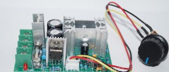
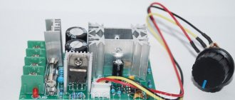
The module is a small board with all the necessary elements for wiring and built on a TDA1085c . A prerequisite for connection is the presence of a tachometer (tachogenerator), which allows for feedback from the electric motor to the microcircuit. When the engine is loaded, the speed begins to drop, which is detected by the tachometer, which commands the microcircuit to increase the voltage and vice versa, when the load weakens, the voltage to the engine drops. Thus, this design allows you to maintain constant power of the commutator motor when the rotor speed changes.
This module fits well with the electric motor from an automatic washing machine . In combination of two devices, you can easily make it yourself: Wood lathe, Milling machine, Honey extractor, Lawn mower, Potter's wheel, Wood splitter, Emery, Drilling machine, Feed cutter and other devices where rotation of mechanisms is necessary.
There is an option for capacitor power supply:
The cost of this board is 57.00 BYN .
Connection
To connect the commutator motor to the control board, you need to understand the pinout of the wires. A standard commutator motor has 3 groups of contacts: tachometer, brushes and stator winding. Rarely, there may also be a 4th group of thermal protection contacts (the wires are usually white).
Tach sensor : located at the rear of the engine with wires coming out (smaller in cross-section than the others). The wires can be probed with a multimeter and may have a slight resistance.
Brushes : wires connect with each other and the engine commutator.
Winding : wires have 2 or 3 terminals (with a middle point). The wires communicate with each other.
When connecting the commutator motor to a 220 Volt network:
We short-circuit one end of the brush and winding wires (or put a jumper in the terminal block), connect the other end of the wires to a 220V network. The direction of rotation of the motor will depend on which of the winding wires will be connected to the 220V network. If you need to change the direction of movement of the motor, place a jumper on another pair of “winding-brush” wires.
When connecting a brushed motor to the speed controller board:
We connect the wires that connected the engine to the 220V network to the “ M” . to the Taho . to the “LN” . Polarity doesn't matter.
The kit includes a switch (terminal SA ). If a switch is not needed, install a jumper.
Settings
The board provides 3 types of settings:
— adjusting the smoothness of the speed increase;
— setting the speed control range.
For operational reliability and correct setup, it is recommended to perform the setup in the following sequence:
1) Setting the smoothness of the set of revolutions is carried out by trimming resistor R1 , which is responsible for the smoothness of the set of revolutions of the commutator motor.
2) The tachometer is adjusted using trimming resistor R3, which allows you to eliminate jerking and jerking in engine operation when adjusting the rotation speed.
3) The speed adjustment range is adjusted using trimming resistor R2 . The setting allows you to limit or increase the minimum speed of the commutator motor, even with the potentiometer turned down to the minimum.
Reverse connection
To connect the reverse switch, you need to remove the jumper in the motor (winding and brushes). The wires in the switch are separated by three pairs of wires, one of which has tinned ends. The pair with tinned ends is connected to terminal M. The remaining two pairs are connected to the winding and brushes. Which pair will be connected to the winding or brushes does not matter. The polarity of the connection does not matter.
A pair of wires for connecting to the engine tach sensor is green or black.
The reverse switch is not included in the standard package of the board and must be purchased separately.
Scheme for connecting the reverse to the board:
Board is customized and tested before sale!
Specifications
Regulator-stabilizer of the frequency of rotation of the commutator motor with MK
Currently, along with asynchronous and commutator AC motors, DC commutator motors are widely used in everyday life and in production. Their advantage is due, first of all, to the simplicity of the control circuit, since there is no need to use expensive frequency converters.
Small brushed DC motor
To stabilize the rotation speed of such engines, it is possible to do without bulky and difficult to maintain systems based on rotor position sensors and tachogenerators. In addition, these engines provide significant torque, with the ability to regulate the rotor speed over a wide range (from the maximum operating frequency, exceeding 5000 rpm for some engines, to almost zero).
Based on the principle of operation, control circuits for brushed DC motors can be divided into two main groups:
- circuits with pulse-width control of the engine rotor speed;
- circuits with phase control of the engine rotor speed.
The operating principle inherent in the first of them provides acceptable parameters. The circuit operates at frequencies of 1...20 kHz; powerful transistors are used as key elements. However, in practice, this circuit does not provide adequate reliability due to the unstable operation of transistors at high pulse currents. When overloaded, expensive power transistors often fail.
The method with phase control of rotational speed, where thyristors are used as control elements, has proven to be much more reliable. However, industrial schemes that use this principle are quite cumbersome. As a result of the analysis of some of these circuits, it turned out that it is possible to significantly simplify them without any deterioration in the technical characteristics of the device. The stability of the engine speed in the circuit shown in Fig. 1 is not inferior to most expensive imported PWM controllers, and is significantly superior to them in reliability. The circuit is designed to regulate the speed of commutator motors such as KPA, KPK or similar with a power from 90 to 250 W and a rated voltage of 12...48 V. In practice, there have been practically no cases of failure of semiconductor elements in this circuit. Even when setting fuse FU1 to a current significantly higher than the rated one in the event of an overload or jamming of the motor, the 5-watt resistive shunt R2 burned out. All other elements of the circuit remained operational.
Rice. 1
As noted above, the operation of the circuit shown in Fig. 1 is based on the principle of phase adjustment of the rotation speed of a commutator motor using current and voltage feedback. Thus, this scheme makes it possible to ensure stable engine speeds with significant fluctuations in the load on the shaft, as well as in the supply voltage. It is possible to implement a mode where, as the load increases, the engine speed increases.
In the described design, microprocessor control of the circuit is implemented, but analog control can also be used using a variable resistor.
The ATMEGA8515 microcontroller implements the following functions:
- setting the engine speed using the “-” and “+” buttons;
- display of set values on a two-digit seven-segment digital indicator (values from 00 to 99);
- automatic saving of specified settings into non-volatile memory;
- playing a melody when the power is turned on;
- generation of sound signals when buttons are pressed;
- auto-repeat when pressing the task buttons for a long time.
The output voltage for controlling the engine speed is generated by the microcontroller part of the circuit using pulse width modulation (PWM). The device shown in Fig. 1 uses one control channel, however, thanks to the PWM software implementation, if necessary, the number of control channels here can be increased to five.
To power the stabilization unit and the engine itself, a powerful power transformer TP1 with a rated output voltage of 24...48 V and a power of 200...500 W is used, depending on the power of the engine used. It should be remembered that when commutator motors are overloaded, their current can exceed the rated current several times. This should guide you when choosing a transformer; it must have at least a double power reserve.
Considering that when the engine is overloaded, the voltage on transformer TP1 may sag and ripples may increase significantly, in order to increase reliability, the controller part of the device is powered from a separate power supply on transformer TP2 with a rated output voltage of 12 ... 15 V and a power of about 5 W. The voltage removed from this transformer is rectified by the diode bridge VD2 and supplied to the integrated stabilizer DA2, which provides an output voltage of 5 V required to power the DA3 controller.
The power part of the circuit is powered by a rectified pulsating voltage of 24...48 V, taken from the diode bridge VD1. The stabilized smoothed voltage for powering op-amp DA1 is formed by a stabilizer assembled on transistor VT1, resistors R3, R7, R19, capacitors C4, C6, C10 and zener diode VD7. Diode VD4 separates the pulsating voltage required for the operation of thyristor VS1 and the smoothed voltage required by the voltage stabilizer. The HL1 LED is used to indicate the supply voltage and the functionality of the stabilizer.
The reference voltage for the engine rotation speed setting circuit is formed by the zener diode VD8. The voltage that sets the engine rotation speed is removed from resistor R21 and, through a filter on elements R22, C8, R24, is supplied to the non-inverting input of op-amp DA1 (pin 3), where it is added to the current feedback voltage. This voltage is removed from the resistive shunt R2 and through a divider on resistors R4, R6 and filter R8, C7, R20 is supplied to the specified input of the op-amp. Elements VD5, VD6, R5 serve to limit the current feedback voltage to the required level.
At the inverting input 2 of op-amp DA1, the voltage removed through resistors R25, R31, R32 from the motor armature M is summed with the reference voltage coming from the zener diode VD8 through resistors R29, R30.
The voltage from the output of integrator DA1 controls the pulse shaper on the unijunction transistor VT6, which determines the opening angle of the thyristor VS1. In this way, phase control of the motor rotor speed is carried out with current and voltage feedback. To control the thyristor VS1, a pulse transformer TRZ is used, connected to the pulse shaper circuit (C11, VT6, R38, R39, VD9).
After assembling the device and checking the correct installation, you need to connect the programmer to the circuit via connector XS1 and flash the DA3 controller.
The controller fuses are configured to operate from an internal RC oscillator with a frequency of 8 MHz, the voltage reduction detector (B0D) is turned on, and the control voltage is set to 4.3 V. The full configuration of the fuses in the CodeVisionAVR program is shown in Fig. 2 .
Rice. 2.
Settings
Debugging of the circuit begins with checking the functionality of the controller part. To do this, without inserting fuse FU1, connect the device to the network, while the indicators HL2-HL3 should display zeros, and a melody should be played in the speaker BA1. Each time you press the SA2 button, the values on the indicator should increase by one (when you press SA1, they should decrease accordingly), and a sound signal should sound in the speaker. If you hold down any button for a long time, auto-repeat should begin. Next, check the operation of the PWM driver; to do this, connect a voltmeter to the connection point of elements 05, R9, R10, and make sure that the voltage here smoothly changes from 0 to 5 V (when the values on the indicators change from 0 to 99, respectively).
Before setting up the power part of the device, it is necessary to organize a stand that allows you to quickly control the engine rotor speed and change the load on the shaft. The simplest and most convenient tachometer can be a conventional universal magnetic head from a cassette recorder, which has exhausted its service life. It is fixed at a distance of several millimeters from the motor shaft. A small piece of magnet is securely attached to the shaft (for example, using electrical tape) so that it crosses the magnetic gap of the head when the motor shaft rotates. The output contacts of the head are connected to an oscilloscope. Changing the load on the shaft for motors with power up to 200 W can be done by pressing a piece of thick rubber against it. In addition, an adjustable AC voltage source of 24…48 V is required for setup.
Before setting up the power part of the device, instead of a constant resistor R4, install a trimmer (for engines KPA-563, KPK-564 or similar - 470 Ohms at a supply voltage of 42 V). The trimmer resistor R9 is set to the middle position. By inserting fuse FU1 into the socket, you can begin debugging. When the power is turned on, the HL2-HL3 indicators should display the previously set values, and the HL1 indicator should also light up, indicating normal operation of the stabilizer circuit.
Using the SA1 button, set the zero voltage at the output of the PWM driver by setting the value to “00”. After applying the supply voltage, trimming resistor R29 ensures that the motor armature stops completely and there is no voltage on it. Then, by changing the position of the trimmer resistor R21, the motor shaft begins to rotate. Next, by pressing the buttons, set the value “50” on the digital indicator and, having achieved a stable position of the signal on the oscilloscope screen, load the motor shaft. By changing the resistance of resistor R4, we achieve constant engine speed (the signal on the oscilloscope screen should not “float”) when the load on the shaft changes. Next, the tuning resistor R4 is unsoldered, the resistance value set on it is measured, and a constant resistor of the appropriate value is soldered in instead. The desired range of engine speed adjustment, when changing values from “00” to “99”, is set with trimming resistor R9.
To adjust the voltage stabilization unit, the input voltage of the circuit is reduced by 10...20% using LATRA and by rotating the trimming resistor R25, the stability of the engine speed is achieved. Afterwards, the zero values on the indicator are again set and the tuning resistor R21 is used to achieve the required initial engine speed.
Details
As a diode bridge VD1, you can use any one with a suitable current for a voltage of at least 100 V. Diode bridge VD2 for a current of 0.5...1 A.
As motors, in addition to KPA, KPT, you can use a wide variety of brushed motors (for example, automobile motors from windshield wipers) for a voltage of 12...48 V, both with permanent magnets and with an independent field winding (OB). In this case, the OB is connected directly to the output of the diode bridge VD1. When using 12 V motors, the voltage on transformer TP1 can be reduced to 24 V.
Transformer TP1 can be used TPP-321, 322 with a typical output voltage of 42 V, or you can make it yourself, taking into account the above. As a transformer TRZ instead of MIT-4, you can use almost any suitable pulse transformer designed to control thyristors or triacs.
The domestic thyristor VS1 can be replaced with an imported VT152 in a plastic case; the radiator for it is selected based on the maximum load currents.
Resistive shunt R2 with a nominal resistance of 0.1...0.15 Ohm with a power of at least 5 W.
Indicators HL2-HL3 can be used any paired with a common anode. The BA1 dynamic head is small-sized and suitable for volume.
Program for microcontroller ()
Author: Victor Tushnov, Lugansk
Source: Radioamator No. 2, 2015
Speed controller for commutator motor from washing machine
The motor from a washing machine, which is great for homemade items, has too high speeds and a short lifespan at maximum speeds. Therefore, I use a simple homemade speed controller (without loss of power). The scheme was tested and showed excellent results. The speed is adjustable from approximately 600 to max.
The potentiometer is electrically isolated from the network, which increases the safety of using the regulator.
The triac must be placed on the radiator.
Almost any optocoupler (2 pcs), but EL814 has 2 counter LEDs inside, and is suitable for this circuit.
A high-voltage transistor can be installed, for example, IRF740 (from a computer's power supply), but it would be a pity to install such a powerful transistor in a low-current circuit. Transistors 1N60, 13003, KT940 work well.
Instead of the KTs407 bridge, a 1N4007 bridge, or any one with >300V, and a current of >100mA, is quite suitable.
Signet in .lay5 format. The signet is drawn “View from the M2 side (soldering)”, so when printing it on the printer it must be mirrored. Color M2 = black, background = white, do not print other colors . The outline of the board (for cutting) is made on the M2 side, and will indicate the boundaries of the board after etching. It should be removed before sealing parts. A drawing of parts from the mounting side has been added to the signet for transfer to the signet. It then takes on a beautiful and finished look.
Extending engine life is very easy
The problem in any household is the lifespan of electric tools. To extend it, use a soft start when turned on. The speed controller also solves this problem.
The physics of the process is such that at the moment the engine is turned on, a powerful impulse of starting current is created. Exceeding the operating current of the motor, it creates sparking in the contact of the commutator with the brushes, which causes rapid wear.
The starting current can lead to burnout of the motor windings and wear of the gearbox due to jerking when starting. Soft start makes working with power tools safe and maintains its serviceability.
How to make a speed controller for a brushed motor?
When using an electric motor in tools, one of the serious problems is adjusting the speed of their rotation. If the speed is not high enough, then the tool is not effective enough.
If it is too high, then this leads not only to a significant waste of electrical energy, but also to possible burnout of the tool. If the rotation speed is too high, the operation of the tool may also become less predictable. How to fix it? For this purpose, it is customary to use a special rotation speed controller.
The motor for power tools and household appliances is usually one of 2 main types:
- Commutator motors.
- Asynchronous motors.
In the past, the second of these categories was most widespread. Nowadays, approximately 85% of motors used in electric tools, household or kitchen appliances are of the commutator type. This is explained by the fact that they are more compact, they are more powerful and the process of managing them is simpler.
The operation of any electric motor is based on a very simple principle: if you place a rectangular frame between the poles of a magnet, which can rotate around its axis, and pass a direct current through it, the frame will rotate. The direction of rotation is determined according to the “right hand rule”.
This pattern can be used to operate a commutator motor.
The important point here is to connect the current to this frame. Since it rotates, special sliding contacts are used for this. After the frame rotates 180 degrees, the current through these contacts will flow in the opposite direction. Thus, the direction of rotation will remain the same. At the same time, smooth rotation will not work. To achieve this effect, it is customary to use several dozen frames.
How to properly connect a speed controller to an electric motor
A motor speed controller may be needed if you are assembling a machine or trying to improve a factory one. Incorrect connection can result in a loss of power or even damage to the motor. Below you will learn how to install and assemble a speed control while maintaining power.
Speed controller circuit for an electric motor
Of course, a 220V electric motor speed controller can be bought in a store, but:
- It is difficult to find boards for mains voltage in stores (the main part of the market is regulators up to 35 volts).
- Those sold for network engines are of mediocre quality. They do not support power and speed, so they are not suitable for machine tools (for example, lathes) in principle.
- Industrial controllers that maintain speed and power are very expensive and difficult to purchase.
Why not collect it then? All parts are sold at any radio store, and you won’t need to program or flash anything, although you will need a microcircuit.
Controller Specifications
The circuit will have the following characteristics:
- Operating voltage - from 110 to 230 volts.
- Adjustment possibilities – 9 – 99%. In general, this indicator depends on the chosen dimer.
- Load – up to 2.5 kilowatts.
- Operating power – 300 watts without radiator. If you install good cooling, you can increase it by 20-25%.
This speed controller circuit for a 220V brushed motor is quite quiet and has a smooth start. Assembling it is quite simple.
The simplest regulator circuit
Refer to this diagram. To reduce the speed of the electric motor, you need a PWM modulator, also known as a triac. This is a microcircuit that modulates a PWM signal, which allows you to set its own frequency.
In this circuit, the role of a modulator is played by the U2008B chip. This inexpensive board is designed specifically for adjusting the speed of an asynchronous motor.
According to the Electrical Systems company website, you will also need a diode and a resistor to reduce the voltage. In the diagram they are shown with signs D1 and R1. Also, to filter the incoming electricity, a power capacitor, designated C1, is needed.
P1, R5 and R3 are voltage dividers designed to regulate voltage. The second resistor is needed to synchronize the internal motor blocks with the triac.
To keep the frequency regulator safe, it is recommended to install a regular 1.5 amp fuse.
If you want to make a professional board, grab this printable circuit:
All that remains is to transfer it to foil PCB and etch it. You can view the instructions here. The asking price for such a regulator is 200 rubles.
Factory regulators
In some cases, it is more profitable to take a speed controller of a commutator or asynchronous motor if you are going to modernize industrial equipment.
The most common models:
1 Motor Speed Controller 400W. Inexpensive (1300 rubles) PWM controller with simple controls. The main panel has an on/off button and a 10-step dimmer. It has high performance and is capable of driving motors up to 400 watts. There is a good cooling and protection system inside. Connection instructions for it will be described below.
2 KLS 4000-A1. Perhaps one of the most powerful Chinese rotation controllers. No connection required as such. Simply insert the plug into the socket on the case. There is a screen where the revolutions per minute are displayed. Perhaps this is the most convenient way to adjust the speed of a brushed motor without loss of power. The price starts from 2400 rubles from China. In Russia it is sold at a 1.5 times premium.
Device
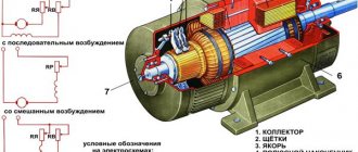
A commutator motor usually consists of a rotor (armature), stator, brushes and tachogenerator:
- The rotor is the rotating part, the stator is the external magnet.
- Brushes made of graphite are the main part of the sliding contacts, through which voltage is applied to the rotating armature.
- A tachogenerator is a device that monitors rotational characteristics. In the event of a violation of the uniformity of movement, it adjusts the voltage supplied to the engine, thereby making it smoother.
- The stator may contain not one magnet, but, for example, 2 (2 pairs of poles). Also, instead of static magnets, electromagnet coils can be used here. Such a motor can operate on both direct and alternating current.
The ease of adjusting the speed of a commutator motor is determined by the fact that the rotation speed directly depends on the magnitude of the applied voltage.
In addition, an important feature is that the rotation axis can be directly attached to a rotating tool without the use of intermediate mechanisms.
If we talk about their classification, we can talk about:
- DC motors
- commutator motors .
In this case, we are talking about what kind of current is used to power the electric motors.
The difference lies in how these connections are organized.
Here it is customary to distinguish:
- Parallel excitation.
- Consistent excitation.
- Parallel-sequential excitation.
Features of speed control
It is important to know that each motor, when rotating, consumes not only active, but also reactive power. In this case, the level of reactive power will be higher, which is due to the nature of the load. In this case, the task of designing devices for regulating the rotation speed of commutator motors is to reduce the difference between active and reactive powers. Therefore, such converters will be quite complex, and it is not easy to make them yourself.
You can construct only some semblance of a regulator with your own hands, but there is no point in talking about saving power. What is power? In electrical terms, it is the current drawn multiplied by the voltage. The result will give a certain value that includes active and reactive components. To isolate only the active one, that is, to reduce losses to zero, it is necessary to change the nature of the load to active. Only semiconductor resistors have these characteristics.
Therefore, it is necessary to replace the inductance with a resistor , but this is impossible, because the motor will turn into something else and obviously will not set anything in motion. The goal of lossless regulation is to maintain torque, not power: it will still change. Only a converter can cope with such a task, which will control the speed by changing the duration of the opening pulse of thyristors or power transistors.
Adjustment
Now let's talk about how you can regulate the speed of commutator motors.
Due to the fact that the rotation speed of the motor simply depends on the amount of voltage supplied, any means of adjustment that are capable of performing this function are quite suitable for this. Let's list a few of these options as examples:
- Laboratory autotransformer (LATR).
- Factory control boards used in household appliances (you can use, in particular, those used in mixers or vacuum cleaners).
- Buttons used in the design of power tools.
- Household lighting regulators with smooth action.
However, all of the above methods have a very important flaw. Along with the decrease in speed, the engine power also decreases. In some cases, it can be stopped even just with your hand. In some cases, this may be acceptable, but in most cases, it is a serious obstacle.
A good option is to adjust the speed using a tachogenerator. It is usually installed at the factory. If there are deviations in the motor rotation speed, an already adjusted power supply corresponding to the required rotation speed is transmitted through the triacs to the motor. If you integrate motor rotation control into this circuit, then there will be no loss of power.
How does this look constructively? The most common are rheostatic rotation control, and those made using semiconductors.
Frequency control
To solve this problem, frequency converters (drivers, inverters) are used, which are connected to the device. They provide rectification of the voltage coming from the source. The units inside generate voltage and frequencies at the required levels. Next, these parameters are supplied to the electric motor.
Stabilization of a 12V commutator motor All characteristics necessary for regulating operation are calculated by the frequency operator itself, focusing on internal algorithms that are installed by the manufacturer.
Among the advantages of this method it is worth highlighting:
- quickly achieve smooth adjustment of the speed of the electric motor;
- the ability to change the speeds and directions of rotation of the motors;
- the required parameters are independently supported;
- economic benefits.
Among the weaknesses, it is worth highlighting the mandatory presence of a converter, which must be purchased separately. But, in fairness, we note that the price of frequency devices is low and they can easily fit into the budget of any home, household, or enterprise.
How to make it yourself?
There are various options for adjustment schemes. Let us present one of them in more detail.
Here is how it works:
Initially, this device was developed to adjust the commutator motor in electric vehicles. We were talking about one where the supply voltage is 24 V, but this design is also applicable to other engines.
The weak point of the circuit, which was identified during testing of its operation, is its poor suitability at very high current values. This is due to some slowdown in the operation of the transistor elements of the circuit.
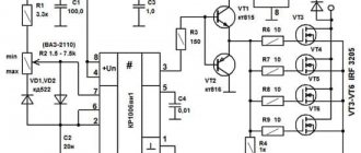
It is recommended that the current be no more than 70 A. There is no current or temperature protection in this circuit, so it is recommended to build in an ammeter and monitor the current visually. The switching frequency will be 5 kHz, it is determined by capacitor C2 with a capacity of 20 nf.
At the same time, it is recommended to select the value of R1 in such a way as to correctly configure the operation of the regulator. From the output of the microcircuit, the control pulse goes to a push-pull amplifier using transistors KT815 and KT816, and then goes to the transistors.
The printed circuit board has a size of 50 by 50 mm and is made of single-sided fiberglass:
This diagram additionally shows 2 45 ohm resistors. This is done for the possible connection of a regular computer fan to cool the device. When using an electric motor as a load, it is necessary to block the circuit with a blocking (damper) diode, which in its characteristics corresponds to twice the load current and twice the supply voltage.
Operating the device in the absence of such a diode may lead to failure due to possible overheating. In this case, the diode will need to be placed on the heat sink. To do this, you can use a metal plate that has an area of 30 cm2.
Regulating switches work in such a way that the power losses on them are quite small. In the original design, a standard computer fan was used. To connect it, a limiting resistance of 100 Ohms and a supply voltage of 24 V were used.
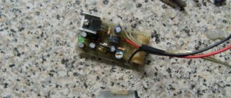
The assembled device looks like this:
When manufacturing a power unit (in the lower figure), the wires must be connected in such a way that there is a minimum of bending of those conductors through which large currents pass. We see that the manufacture of such a device requires certain professional knowledge and skills. Perhaps in some cases it makes sense to use a purchased device.
Design Features
The microcircuit is equipped with everything necessary for high-quality engine control in various speed modes, from braking to acceleration and rotation at maximum speed. Therefore, its use greatly simplifies the design, while simultaneously making the entire drive universal , since you can select any speed with a constant torque on the shaft and use it not only as a drive for a conveyor belt or drilling machine, but also for moving a table.
The characteristics of the microcircuit can be found on the official website. We will indicate the main features that will be required to construct the converter. These include: an integrated frequency-to-voltage conversion circuit, an acceleration generator, a soft starter, a Tacho signal processing unit, a current limiting module, etc. As you can see, the circuit is equipped with a number of protections that will ensure stable operation of the regulator in different modes.
The figure below shows a typical circuit diagram for connecting a microcircuit.
The scheme is simple, so it is quite reproducible with your own hands. There are some features that include limit values and speed control method:
- The maximum current in the motor windings should not exceed 10 A (subject to the configuration shown in the diagram). If you use a triac with a large forward current, the power can be higher. Please note that you will need to change the resistance in the feedback circuit downward, as well as the inductance of the shunt.
- The maximum rotation speed is 3200 rpm. This characteristic depends on the type of engine. The circuit can control motors up to 16 thousand rpm.
- Acceleration time to maximum speed reaches 1 second.
- Normal acceleration is achieved in 10 seconds from 800 to 1300 rpm.
- The engine uses an 8-pole tachogenerator with a maximum output voltage of 30 V at 6000 rpm. That is, it should produce 8 mV per 1 rpm. At 15,000 rpm it should show 12 V.
- To control the motor, a 15A triac with a maximum voltage of 600 V is used.
If you need to organize a motor reverse, then for this you will have to supplement the circuit with a starter that will switch the direction of the excitation winding. You will also need a zero speed control circuit to give permission for reverse. Not shown in the picture.
Selection criteria and cost
In order to correctly choose the most suitable type of regulator, you need to have a good idea of what types of such devices there are:
- Various types of control. Can be a vector or scalar control system. The former are used more often, while the latter are considered more reliable.
- The power of the regulator must correspond to the maximum possible power of the motor.
- Based on voltage, it is convenient to choose a device that has the most universal properties.
- Frequency characteristics. The regulator that suits you should match the highest frequency that the motor uses.
- Other characteristics. Here we are talking about the length of the warranty period, dimensions and other characteristics.
Depending on the purpose and consumer properties, prices for regulators can vary significantly.
For the most part, they range from approximately 3.5 thousand rubles to 9 thousand:
- Speed controller KA-18 ESC , designed for 1:10 scale models. Costs 6890 rubles.
- MEGA speed controller is manifold (waterproof). Costs 3605 rubles.
- Speed controller for LaTrax 1:18 models. Its price is 5690 rubles.
Generalized controller circuit
An example of a controller that implements the principle of controlling a motor without power loss is a thyristor converter. These are proportional-integral circuits with feedback, which provide strict control of characteristics, ranging from acceleration-braking to reverse. The most effective is pulse-phase control: the repetition rate of the unlocking pulses is synchronized with the network frequency. This allows you to maintain torque without increasing losses in the reactive component. The generalized diagram can be represented in several blocks:
- power controlled rectifier;
- rectifier control unit or pulse-phase control circuit;
- tachogenerator feedback;
- current control unit in the motor windings.
Before delving into a more precise device and principle of regulation, it is necessary to decide on the type of commutator motor. The control scheme for its performance characteristics will depend on this.
Types of engines and operating principles
Motors are divided into three types: commutator, asynchronous and brushless. Most power tools use the first type. This electric motor has a fairly compact size. Its power is significantly higher than that of asynchronous, and the price is quite low. As for asynchronous ones, this type is mainly used in the metalworking industry, and they are also widespread in coal mines. Quite rarely they can be found in everyday life.
The brushless electric motor is used where high speeds, precise positioning and small dimensions are needed. For example, in various medical equipment, aircraft modeling. The principle of operation is quite simple. If a rectangular frame, which has an axis of rotation, is placed between the pluses of a permanent magnet, then it will begin to rotate. The direction depends on the direction of the current in the frame. This type contains an armature and a stator. The armature rotates, but the stator stands still. As a rule, there is not one frame at anchor, but 4.5 or more.
An asynchronous motor works on a different principle. Thanks to the effect of an alternating magnetic field in the stator coils, it is driven into rotation. If you delve deeper into the course of physics, you can remember that a kind of magnetic field is created around the conductor through which the current passes, causing the rotor to rotate.
The principle of operation of the brushless type is based on turning on the windings so that the magnetic fields of the stator and rotor are orthogonal to each other, and the torque is regulated by a special driver.
Adjusting the speed of electric motors increases the scope of their applications
Cutting metal, stone, wood, polishing a car body, using diamond discs and discs of different diameters - all these works require choosing a motor rotation speed that would be safe to operate and would not damage the material being processed.
To achieve these goals, there are electric motor speed controllers. Some power tools have built-in speed controllers; economy-class tools do not have regulators, but in the technical literature and on the World Wide Web there are many diagrams and recommendations on how to make an engine speed controller with your own hands.
Commutator motor design
A commutator motor consists of a stator and a rotor. The rotor is the part that
rotates, but the stator is stationary. Another component of the electric motor is graphite brushes, through which current flows to the armature. Depending on the configuration, Hall sensors may be present, which make it possible to smoothly start and adjust the speed. The higher the applied voltage, the higher the speed. This type can operate on either AC or DC power.
According to the classification, commutator motors can be divided into those that operate on alternating current and direct current. They can also be divided according to the type of winding excitation: motors with parallel, series and mixed (parallel-series) excitation.
Basic functions of the speed controller
The use of such converters allows you to achieve many goals, namely:
- the possibility of stepwise acceleration and reduction of electric motor speed, which leads to reduced loads and less electrical energy consumption;
- you can carry out a smooth start, and with instantaneous maximum acceleration, the motor receives ultra-high loads, overheating the windings and other drives;
- as a means of additional protection of electronic mechanisms;
- reduction in maintenance costs for power units and pumps, as the risks of drive failures, as well as individual mechanisms, are reduced.
Welding machines, voltage stabilizers, PCs, TVs, etc. cannot do without similar built-in devices.
Types of adjustment
There are quite a few options for adjusting the speed . Here are the main ones:
- Power supply with adjustable output voltage.
- Factory adjustment devices that initially come with the electric motor.
- Push-button regulators and standard regulators that simply limit the voltage.
These types of adjustments are bad because as the voltage decreases or increases, the power also drops. In some power tools this is acceptable, but, as practice shows, in most cases this is unacceptable due to a strong drop in power and, accordingly, efficiency.
The most acceptable option would be a regulator based on a triac or thyristor. Not only does such a regulator not reduce power when the voltage decreases, it also allows for smoother starting and speed control. In addition, such a scheme can be made with your own hands. Below is a picture of the speed control with power maintenance. The circuit is assembled on the basis of a BTA 41,800 V triac .
All ratings of electrical elements are indicated in the diagram . This is the circuit after assembly, it works quite stably and provides smooth adjustment of the brushed motor. When the output voltage decreases, the power does not decrease, which is a significant plus.
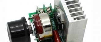
If desired, you can assemble the speed controller of a 220 V brushed motor with your own hands. This circuit is assembled on the basis of a VTA26-600 triac, which must first be installed on a radiator, since this element gets quite hot under load.
It is possible to connect an electric motor with a power not exceeding 4 kW to the finished circuit.
The diagram looks like this.
It can successfully cope with the adjustment of power tools such as a drill, grinder, circular saw, and jigsaw. If desired, you can use the circuit as a power regulator for heating elements, heaters, and as a dimmer. The disadvantages include the impossibility of adjusting the power of devices powered by direct current.
Basic tips for masters
Before choosing the most effective regulator option, it is worth considering some tips:
- one of the most important criteria when choosing is power, which must exceed or correspond to the data on the device or unit used;
- for commutator motors, vector regulators are often chosen, but scalar ones are more reliable;
- the voltage must be within the permissible range;
- the wires are chosen not to be too long;
- reliable soldering of joints and good insulation;
- since the main purpose of the device is frequency conversion, this aspect is selected in accordance with certain technical requirements.
It turns out that with effort, you can reduce the noise level of a PC fan by reducing the voltage and speed using a transistor and two resistors.
This type of work on assembling a simple controller is useful for gaining additional useful skills, and it will also help save money.
Note!
Do-it-yourself illuminated mirror - step-by-step master class on how to make it yourself, photos of types of lighting
DIY flower stand - TOP 100 photos of stand options, detailed instructions, diagrams and drawings from the masters
Do-it-yourself furniture restoration: restoration methods, step-by-step master class, necessary tools and materials
DC Power Regulators
Sometimes there is a need to adjust the speed of a brushed DC motor.
If the consumer does not have a lot of power, then it is possible to connect a variable resistor in series, but then the efficiency of such a regulator will drop sharply. There are schemes with which it is possible to regulate the speed quite smoothly without reducing efficiency. Such a regulator is suitable for changing the brightness of various lamps, supply voltage not exceeding 12 V. This circuit also acts as a speed stabilizer; when the mechanical load on the shaft changes, the speed remains unchanged.
This 12V DC motor speed controller circuit is quite suitable for regulating and stabilizing the speed of motors with a current not exceeding 5 A. This circuit includes a bipolar transistor driver and a 7555 timer, which ensures stable operation and smooth regulation speed. The price of the parts is quite low, which is a definite plus. You can also assemble a 12 V electric motor speed controller with your own hands.
Overview of typical circuits
You can regulate the rotation of the shaft of a low-power electric motor by connecting a power resistor in series with no. However, this option has very low efficiency and the inability to smoothly change speed. To avoid such a nuisance, you should consider several regulator circuits that are used most often.
Features of the first option:
- The PWM transistor has a sawtooth voltage generator with a frequency of 150 Hz.
- The operational amplifier acts as a comparator.
- To change the speed, a variable resistor is used that controls the duration of the pulses.
As you know, PWM has a constant pulse amplitude. In addition, the amplitude is identical to the supply voltage. Consequently, the electric motor will not stop even when running at low speeds.
The second option is similar to the first. The only difference is that an operational amplifier is used as the master oscillator. This component has a frequency of 500 Hz and produces triangular-shaped pulses. Adjustment is also carried out using a variable resistor.
Motor design
Structurally, the engine from the Indesit washing machine is simple, but when designing a controller to control its speed, it is necessary to take into account the parameters. Motors may have different characteristics, which is why the control will also change. The operating mode is also taken into account, which will determine the design of the converter. Structurally, the commutator motor consists of the following components:
- An armature, it has a winding laid in the grooves of the core.
- Collector, a mechanical rectifier of alternating mains voltage, through which it is transmitted to the winding.
- Stator with field winding. It is necessary to create a constant magnetic field in which the armature will rotate.
When the current in the motor circuit, connected according to the standard circuit, increases, the field winding is connected in series with the armature. With this inclusion, we also increase the magnetic field acting on the armature, which allows us to achieve linearity of characteristics. If the field remains unchanged, then it will be more difficult to obtain good dynamics, not to mention large power losses. It is better to use such motors at low speeds, since they are more convenient to control at small discrete movements.
By organizing separate control of the excitation and armature, it is possible to achieve high positioning accuracy of the motor shaft, but the control circuit will then become significantly more complicated. Therefore, we will take a closer look at the controller, which allows you to change the rotation speed from 0 to the maximum value, but without positioning. This may be useful if a full-fledged drilling machine with the ability to cut threads will be made from the engine from a washing machine.
Regulator for 220 Volt motors
A self-made engine speed controller can be mounted in the tool body or made in a separate housing, which significantly improves the convenience and versatility of its use. The self-contained controller can be used as needed for various power tools.
The simplest speed controller for a commutator motor can be made with your own hands in several ways - on a printed circuit board, mounted or mounted on a circuit board.
Main elements of the scheme:
- triac BTA 16;
- dinistor DB 3;
- variable resistor 500 kOhm;
- fixed resistor 2 kOhm;
- capacitance 100 nF;
- foil PCB or circuit board;
- solder;
- rosin;
- ferric chloride;
- laser disc marker and pencil.
Cut a piece of foil PCB of the required size, sand it, degrease it and draw a diagram of the device for subsequent etching in ferric chloride.
After etching, rinse, drill holes for soldering circuit elements, tin the printed tracks and pads, and assemble the circuit.
Instead of making your own printed circuit board, you can buy a ready-made circuit board.
By installing the assembled circuit into an easy-to-use case, you will receive a 220V speed controller made by yourself.
