1.2. Kinematic diagram of a lathe
The kinematic diagram of a lathe is a conventional representation of the totality of all the mechanisms by which the movement of the elements of the machine is carried out; it shows the relationship of individual elements and mechanisms involved in transmitting the movement of various organs of the machine.
There are two kinematic chains in a lathe: electric motor - spindle (main movement chain) and spindle - support (feed chain), which are depicted in two versions - for longitudinal (when cutting threads and turning) and transverse feed of the cutter.
The kinematic chain of a lathe can consist of a number of kinematic pairs of gears or pulleys, worm and screw gears. The sequence of kinematic pairs in the chain is represented by numbers indicating the number of teeth in gears or pulley diameters. For elements of kinematic pairs fixed on one shaft, numbers are written through a dash, and for elements fixed on different shafts - through a division sign.
In Fig. Figure 9 shows a kinematic diagram of a screw-cutting lathe. Let us trace along it the kinematic chain of the main movement: electric motor - spindle. This chain connects the motor shaft (pulley diameter d1 = 142 mm) through a V-belt drive with the pulley of shaft I (pulley diameter d2 = 254 mm) of the lathe gearbox, on which a gear block 56-51 and a gear 50 are loosely mounted. On the shaft There is also a friction plate clutch M1 to impart direct (when turned to the left) or reverse (when turned to the right) rotation to the spindle. When clutch M1 is turned to the left, rotation from shaft I is transmitted to shaft II. A movable block of gear wheels B1 (34-39) is placed on it, which, alternately connecting with the gear wheels of block 56-51, ensures the transmission of different numbers of revolutions to shaft II. Then, from this shaft, using a movable block B2 (47-55-38) on shaft VII and a movable block B5 (43-54) on shaft VII, rotation is transmitted to the spindle (six revolutions).
When the overdrive is turned on (shafts IIV-V), the movement from shaft III is transferred to shaft IIV, which, with the help of moving blocks B3(88-45) and B4(22-45), transmits it to shaft V and then through wheels 27-54 to the spindle ( shaft VII)', we additionally obtain three gear ratios. The structural formula of the kinematic chain has the form (rpm):
[6]
where pshp and ndv are the number of revolutions of the spindle and electric motor per minute; ik s - variable gear ratio of the gearbox (taking into account the overdrive gear ratio); —belt slip coefficient ( = 0.98).
With the position of the gears shown in Fig. 9, spindle speed during forward stroke
rpm
The 1K62 screw-cutting lathe has 24 spindle revolutions (from 12.5 to 2000 rpm).
Similarly, you can install the kinematic chain of the caliper for longitudinal and transverse feeds, as well as for thread cutting. For example, the structural formula for longitudinal feed (mm/rev):
spr=l.ik p...mz [7]
where ik p is the gear ratio of the feed box (taking into account the gear ratios from the spindle to the reverse, the reverse itself, the replaceable gears of the guitar and the apron mechanism); t—rack and pinion module, mm; g - number of rack and pinion gear teeth.
With the position of the gears shown in Fig. 9, longitudinal feed
In total, the machine has 48 longitudinal feeds (from 0.075 to 4.46 mm/rev) and the same number of transverse feeds (from 0.038 to 2.23 mm/rev).
By analyzing the kinematic diagram of a lathe and its kinematic chains, you can select the necessary structural formula for setting up the machine to perform a specific task.
studfiles.net
Kinematics of machines
Methods for forming production lines when forming the surfaces of manufactured parts.
The surface of any part is formed by the movement of one line (generator) along another line (guide). Both of these lines are called producing. In turn, generating lines are formed by material points or lines of the cutting edge of the tool (depending on the type of tool) due to the coordinated relative movements of the workpiece and the tool. These movements are called shaping movements. Depending on the type of cutting tool and the shape of its cutting edge, there are 4 methods for creating production lines.
| Method name | Sketch | Cutting part of the tool |
| workpiece surface |
| tool surface |
Copying
line (turning - shaped cutters) Slot (turning - turning cutters) Rolling line (knurling, knurling) Touching point (grinding, milling)1. Copying – characterized by the fact that the shape and length of the cutting edge coincides with the shape and length of the line being formed. Here the shape of the generative line is inherent in the tool itself (shaped tools). Therefore, no shaping motion is required for this line.
2. Trace - the line formed is a trace of the movement of the point of the cutting part of the tool and is formed as a result of the relative movement of the workpiece and the tool. For example, this method is implemented when processing cylindrical surfaces with pass-through turning tools on lathes.
3. Rolling - the line formed is formed as an envelope of successive positions occupied by the cutting edge of the tool, which rolls without sliding. The tool makes a rolling motion. The method is implemented when rolling surfaces with rollers, etc.
4. Touch - the line formed is formed in the form of an envelope of the place where many cutting points of the rotating tool touch the surface of the workpiece. This method is typical for the formation of surfaces using cutters, grinding wheels and other multi-edge tools.
Machine movements
All movements in machines, which are called executive, are divided into movements according to their intended purpose:
1. Shape formation (F);
2. Installation (Ust);
3. Divisions (D);
4. Management (Control);
5. Auxiliary (Auxiliary).
1. Shaping movements - these movements (working) are the coordinated relative movements of the workpiece and the cutting tool, as a result of which producing lines are continuously created, and, therefore, the surfaces of the parts being manufactured are formed.
These movements are:
- main movement - ensures separation of chips from the workpiece at a certain cutting speed (V). The main thing is to move at the highest speed. In the case of turning, drilling and a number of other operations, the cutting speed is determined by the formula , where is the processing diameter and is the rotation speed of the machine spindle assembly.
— feed movement (S) – feeds new areas of the workpiece surface under the cutting edges of the tool.
2. Installation movements - bring the cutting tool and the workpiece to a position in which the allowance is removed. Differs from the feed motion with a higher speed; also called rapid approach or retraction of the tool.
3. Division movements – ensure uniform arrangement of identical surfaces formed on the workpiece. For example, the division movement rotates a workpiece mounted on a machine through a given angle when cutting the teeth of gear wheels. The division movements can be either periodic (cutting spur gears) or continuous (helical teeth).
4. Control movements - movements made by the controls, regulation and coordination of all other executive movements of the machine. For example, the movements of reversing devices, cams, couplings, etc.
5. Auxiliary movements - movements associated with transportation, installation, clamping and removal of processed workpieces, removal of chips, etc.
In the formation of the kinematic structure of the machine, the shaping, installation and division movements play a decisive role.
If executive movements are carried out by one elementary movement (rotational or translational), then this is a simple movement [F(V), F(P)]; if several, then complex [F(B1, B2), F(B1, B2, P3)], etc.
Kinematic groups
Executive movements in machine tools are carried out using kinematic groups.
The kinematic group includes:
1. Source of movement;
2. Executive bodies;
3. Settings that provide the required movement parameters;
4. Kinematic connections.
1. The source of motion is the engine. For example, electric motor, hydraulic motor, etc.
2. Executive bodies – movable final links of kinematic groups that are directly involved in the formation of the trajectory of the executive movement. If these executive bodies carry out the movement of the workpiece or cutting tool, then they are called working bodies.
These include:
— spindle units;
— calipers (lathes, etc.)
— machine tables (milling, grinding, etc.)
3. Adjustment bodies - various devices such as speed boxes, feed boxes, replacement gears, variators, etc. Basically, the executive bodies perform rotational or translational motion and are, accordingly, moving links of the rotational (B) or translational (P) executive kinematic a couple.
Depending on the number of executive bodies, kinematic groups can be simple or complex. In simple kinematic groups there is one executive body, in complex ones there are two or more.
Simple kinematic group (Fig. 6)
Complex kinematic group with two rotational kinematic pairs (B1 and B2) (Fig. 7)
A complex kinematic group with two kinematic pairs: rotational (B1) and translational (P2) (Fig. 
In Fig. 6-8:
M – source of motion;
I, II – executive bodies;
UV – main movement chain adjustment organ;
US – feed chain setting element.
4. Kinematic connections are external and internal.
Internal kinematic connection is a set of kinematic links that provide a qualitative characteristic of movement (primarily the trajectory). In simple and complex kinematic groups, the internal connection is implemented differently.
In simple form - the connection of two contacting links of the executive group, one of which is the executive body itself (I in Fig. 6).
In a complex one, there is a kinematic chain connecting the movable executive bodies and ensuring the functional consistency of their movements. In this case, the minimum number of internal kinematic connections is one less than the number of executive bodies. In Fig. 7, 8 the internal kinematic connection is the kinematic chain 1–4–2.
External kinematic connection is a set of kinematic links that provide quantitative characteristics of movement (speed, path). It is designed to transfer energy from the source of motion to the internal kinematic connection. In a simple kinematic group, the external kinematic connection will be chain 1–2 (Fig. 6), and in a complex group – chain 3–4 (Fig. 7, 8).
Kinematic structure of machines
The kinematic structure is determined by a set of kinematic groups that are connected to each other in various ways. When connecting kinematic groups, it must be taken into account whether there are common executive bodies and sources of movement, as well as whether correction in time of the movements created by the groups is required.
From the whole variety of kinematic structures, 3 classes can be distinguished:
1. Kinematic structures of machine tools, which consist of simple kinematic groups, belong to the class of elementary structures and are designated “E”. The shaping movements in these machines are carried out by different simple kinematic groups - F(V) and F(P).
2. Kinematic structures of machine tools, which consist of complex kinematic groups, belong to the class of complex structures and are designated “C”. The shaping movements in these machines are carried out by complex kinematic groups - F(B1, B2) and F(B1, B2, P3), etc.
3. Kinematic structures of machine tools, which consist simultaneously of simple and complex kinematic groups, belong to the class of combined structures and are designated “K”.
Examples:
1. Connection of kinematic groups in machines with a class “E” structure.
The machine has 2 simple kinematic groups, each of which performs a simple shaping movement F(B1) and F(P2). These groups are not kinematically connected to each other; in this case, a constructive connection method is implemented. For example, the 6N82 horizontal milling machine has such a structure.
2. Connection of kinematic groups in machines with a class “C” structure.
In this case, the groups are connected kinematically via an external connection. In the machine, one source of motion M and part of the links in the drive chains are common to 2 kinematic groups.
This structure is available, for example, in universal screw-cutting lathes (16K20, 16B16, 1M610, etc.).
These machines have a fairly developed drive, which is determined by the following:
— the machine must operate in the cutting speed range VMAX ¸ VMIN, this determines the range of speed changes. In this case, VMIN is determined from the cutting speed required for cutting threads with turning thread cutters.
— on these universal machines, the manufactured parts have a significant range of diameters dMAX ¸ dMIN, which determines the range of diameters.
— there is a range of rotation speeds. Spindle speed; By determining the minimum and maximum spindle speeds and , we obtain that . On machines of this type, based on the need for thread cutting, on the one hand, and ensuring cutting at high speeds, on the other hand, the range of rotation speeds is approximately equal to .
Kinematic setup of machines
Kinematic tuning of machine tools comes down to determining the parameters of the tuning elements in order to ensure the specified movements of the machine's executive bodies and, therefore, obtain the required shape and dimensions of the manufactured part. It should be remembered that the movements of the executive bodies are calculated values and depend on the selected cutting speed ().
During kinematic tuning, kinematic balance equations are compiled that connect the initial and final movements, and from the resulting equations the dependences of the parameters of the tuning elements on the calculated movements are found. In metal-cutting machines, replacement gears, gearboxes and feeds, variators and other similar devices are used as tuning elements.
Example: the simplest kinematic diagram.
M – electric motor with a known rotation speed n0, min-1;
d1, d2 – belt pulleys with known diameters, mm;
z1, z2 – gears with unknown numbers of teeth;
nshp – spindle rotation speed, min-1, calculated value.
, where V – cutting speed, calculated or determined according to recommendations, m/min; d – diameter of the workpiece, mm.
The kinematic balance equation describing the relationship between the initial (motor) and final (spindle) links is the expression:
, where is the constant component of the tuning element (from constant - constant); – variable component of the tuning organ (from variable – variable).
The tuning formula is derived from the kinematic balance equation:
.
After determining the value, it is necessary to select a combination of gears with the numbers of teeth z1 and z2, which provides the required parameters of the executive movement.
Machines for processing threads and screw surfaces
Let's consider a kinematic diagram typical of representatives of the class of universal screw-cutting lathes.
1.
Machine bed;
2. Headstock (with gearbox and spindle assembly);
3. Tailstock;
4. Caliper;
5. Cutter;
6. Workpiece being processed.
To kinematically set up a machine, you need to find the main chains (main movement chain and feed chain) and for each chain write a kinematic balance equation and a setup formula.
Main movement chain.
Kinematic balance equation:
Setting formula:
Feed chain.
Kinematic balance equation:
Setting formula:
Thread cutting according to the presented scheme can be carried out, for example, on a machine mod. 16K20. On such machines, the movement of the support with the cutting tool (cutter) is carried out either using a lead screw (mainly when cutting threads) or a lead shaft (when performing most turning operations - turning, trimming, etc.).
When using a lead screw, the conversion of its rotation into translational movement of the caliper is carried out using a “screw-nut” transmission.
When using a drive shaft, the conversion of its rotation into translational movement of the caliper is carried out using a rack and pinion transmission.
A gear mounted on a movable key on the running shaft transmits rotation through a worm and a series of gears to the rack and pinion gear. The rack wheel, being in constant engagement with the rack rigidly fixed to the machine frame, ensures the movement of the caliper and the tool holder mounted on it by rolling in relation to the rack.
On kinematic diagrams, a support with the ability to move from the lead screw and the lead shaft is designated as follows:
The movement of the support with the cutting tool can be carried out either using a lead screw or using a lead shaft, but never at the same time.
The main components of the machine are:
— front headstock – it houses the gearbox and spindle assembly;
— caliper – serves to move the cutting tool relative to the workpiece; consists of a lower carriage for longitudinal movement of the assembly with the tool along the bed guides, transverse slides for transverse movement of the tool, as well as cutting slides for additional movement of the tool when cutting cones;
— apron – it houses controls for the direction and speed of movement of the caliper;
- tailstock - serves to support the rear end of a long workpiece in order to ensure greater rigidity of the system, as well as to secure the rod tool for machining holes.
All of the above components are installed on the machine bed.
Machine drives
The main drives of the machine are:
1. Main movement drive;
2. Feed drive, which serves to carry out specified movements of the workpiece and tool.
1. Main movement drive.
The machines can use drives with stepwise cutting speed control and stepless cutting speed control.
In step-controlled drives, as a rule, asynchronous unregulated AC electric motors are used. In this case, intermediate values of rotation speeds of the executive unit (spindle) are selected according to the law of geometric progression. Speed regulation is carried out using gearboxes.
Advantages:
— high efficiency;
— the ability to provide constant power throughout the entire speed control range;
- relatively low cost.
In drives with stepless regulation, as a rule, adjustable DC motors are used, less often - variators. They are characterized by higher cost, and in the case of using CVTs - reduced reliability.
Advantages:
— increased productivity due to precise setting of the optimal cutting speed;
— the ability to maintain a constant cutting speed when processing a product with a changing diameter.
The drive of the main movement is one hundred step regulation.
Kinematic calculation of the gearbox.
The spindle speeds in these drives vary according to the law of geometric progression, and the geometric series with the denominator has the following form:
– regulation range. Hence, .
The main advantage of these series is that the relative losses in cutting speed due to the use of a lower spindle speed than the required one are constant for all speed ranges.
Standard values for the denominators of geometric series are accepted:
1,06; 1,12; 1,26; 1,41; 1,58; 1,78; 2,0.
After calculations, the nearest greater to is selected.
Small values (1.06) lead to a more complex drive (large gearboxes), so from an economic point of view the use of a continuously variable drive can be justified.
Value = 1.12 is used mainly in machines that require precise adjustment to a given rotation speed (for example, CNC machines).
= 1.26 – mainly in screw-cutting lathes;
= 1.41; 1.58 – drilling and milling machines;
= 1.78 – machines with coarse settings;
= 2.0 – rarely used, mainly on stripping machines.
The multiplier structure of gearboxes is gearboxes consisting of two elementary shaft mechanisms, sequentially connected to each other in one or more kinematic chains. The total number of rotation frequencies is determined by multiplying the numbers of rotation frequencies of the elementary two shaft mechanisms.
The set of gears connecting two adjacent gearbox shafts forms a group of gears, which is characterized by the number of gears “” and the gear ratio “”.
Kinematic diagram of the simplest three-shaft gearbox.
I, II, III – gearbox shafts.
– gears.
– gears rigidly mounted on shafts (on a key).
– a three-crown gear block moving along shaft II along splines.
– a double-crown gear block moving along shaft II along splines.
– gear ratios of pairs of gears.
The presented gearbox has 6 rotation speeds. Changing rotation speeds is carried out using multiplying mechanisms with movable blocks of gear wheels. The presented speed box has 2 multiplying groups.
The 1st group consists of three gears: .
The 2nd group consists of two gears: .
The number of speeds and the kinematic version of the gearbox can be described by the formula:
– number of gears in the first multiplying group;
– number of transmissions in the second multiplying group;
– characteristics of the first and second multiplying groups.
In the general case, the characteristics of subsequent groups are determined by multiplying the gears of all groups kinematically preceding a given group. The characteristic is assigned to the main gear group, all other gear groups are selected.
The structural formula for the presented gearbox can be represented by the expression:
,
where are transmission groups.
– characteristics of gear groups, where “3” is the number of gears of the first group.
Let us assume that shaft IV with two gears between shafts III and IV has been added to the presented gearbox. Then the structural formula of such a gearbox can be presented as follows:
– characteristics of gear groups. is obtained as a result of multiplying the numbers of gears of groups I and II, kinematically preceding gear group III (6=3*2).
The meaning of the group characteristics is the exponent, it shows how many times the rotation speed changes when changing gears of this group. So, when switching gears of the first group, the shaft rotation speed changes by a factor, and when switching gears of the second group - by a factor.
Graphic-analytical method for calculating gearboxes.
You can analyze various options for gearboxes and choose the most rational one using a graphic-analytical method, which includes the construction of structural grids and a graph of rotation speeds.
Example: Structural mesh for the above formula.
Rice. 9
Let us define the conventions and rules for constructing a structural grid:
— vertical parallel lines – sequentially located gearbox shafts (according to the number of shafts in the box);
— horizontal parallel lines drawn at a distance from each other indicate the rotation speed on a logarithmic scale. The intervals between adjacent lines indicate a segment on a scale equal to .
— rays sloping upward indicate overdrive gears; with a downward slope - downward; without tilting - direct transmissions with ;
— the number of rays emerging from one point corresponds to the number of gears between the shafts;
— the gear ratio () of the transmission is generally determined by the expression , where is the number of intervals by which the beam rises or falls;
— the structural mesh is built in accordance with the structural formula (). It reflects the relative relationship between the gear ratios in the groups, therefore the beams for each group are drawn symmetrically, and the number of intervals between the ends of the beams is numerically equal to the characteristic of the gear group. Therefore, 3 beams between shafts I and II have a divergence of 1 interval (), and 2 beams between shafts II and III have a divergence of three intervals ();
— the structural mesh is always built from the middle of the initial shaft (I or 0).
Example: structural grids for formula.
a) Let us choose gear group I (three gears) as the main gear group. Then the structural formula will take the form: .
Rice. 10
b) Let us select gear group III (2 gears) as the main gear group. Then the structural formula will take the form: .
(The structural formula of the gearbox can be written differently with the same number of rotation speeds on the output shaft).
| n12 |
| n11 |
There are criteria for choosing the most rational gearbox option. Let's consider them using the example of possible structural formulas of a gearbox with:
1. From the point of view of ensuring acceptable radial and axial dimensions of gearboxes, it is desirable that the number of beams on the structural grid (i.e., the number of gears in a group) does not exceed 4. Based on this, the first 2 variants of structural formulas do not satisfy the condition, and preference should be given to the formula;
2. A limitation has been accepted (the number of intervals between beams should not exceed 8), and ;
3. Preference is given to the option with a large number of gears between the initial shafts, i.e. fan-shaped chart. This is due to the fact that with small gear ratios in the area of high rotation speeds, better operating conditions for gears are provided, and the main reduction and transmission of large torques is carried out on subsequent shafts. Thus, the option is preferable to the and options, despite the same groups of gears between the shafts, but with a change in the order of their arrangement.
The simplest gearbox we considered above, with the same total number of rotation speeds, could be designed differently: .
Structural mesh:
Rice. 12
Provides the same rotation speeds, but 3 gears operate on the last shafts; In addition, gears operate under more difficult conditions due to the disruption of the fan-shaped mesh.
Plotting a graph of rotational speeds
The rotation frequency graph is constructed according to the structural formula and structural grid. The number of intervals between rays adopted on the structural grid is necessarily preserved, but the inclination of the rays changes, since the graph is asymmetrical.
Let's consider one of the possible options for the rotation speed graph.
With the indicated arrangement of the beams between shafts I and II, their speed is ensured, and the main reduction due to transmission is provided on the last shafts.
In this way, the speed plot helps illustrate the rationality of the gearbox design and adds information that is missing from the structural grid.
Rice. 13
In the general case, the rotation speed graph is constructed from a point on the initial shaft located below .
Unlike the structural grid, the rotation speed graph gives an idea of the specific values of gear ratios and spindle speeds. When drawing beams, restrictions on the maximum permissible values of gear ratios for gears are taken into account:
Example: graphical-analytical calculation of a gearbox.
Initial data for calculation:
1. Determine the range of rotation speeds and the denominator of the geometric series:
2. We write down the structural formula of the gearbox:
The final choice of the structural formula is made after comparing several options.
3. Let’s build and analyze possible structural grids:
A) .
Strictly speaking, taking into account the V-belt transmission, the formula should look like , however, the first group of gears can be ignored for simplicity, since it does not affect the number of gears and the characteristics of subsequent groups of gears. The structural grid for this formula was discussed above (Fig. 9).
b)
The structural grid for this formula was also discussed above (Fig. 12).
V)
In this option, we will select the group between shafts II and III as the main gear group. The horizontal line between shafts 0 and I represents the V-belt drive.
Rice. 14.
Analyzing three options for structural grids according to the above criteria, we come to the conclusion that the most rational option is “a”, which will be used in the future when constructing a graph of rotation frequencies.
4. Let's build a graph of rotation speeds:
First, let's determine the rotation speed of the output shaft (spindle) of the gearbox.
There may be several options for rotation speed graphs. The basic rule for constructing the graph is the need to strive to gradually reduce the electric motor speed to a given minimum gearbox frequency, ensuring the main reduction on the last shafts (II-III). The construction of the graph begins with the construction of a circuit that provides.
Rice. 15.
First, we reduce the rotation speed of the electric motor to a value using a V-belt transmission with a gear ratio. Based on this gear ratio, the diameters of the V-belt pulleys are determined. Using the transmission, we reduce the rotation speed of shaft II to , and then, using the transmission, we ensure the main reduction in the rotation speed of shaft III to . Having built a circuit to provide , we often build the rest of the graphics according to the selected structural grid, taking into account the divergence of rays accepted on it.
Taking into account the requirement for high speed of the first shafts, this option is more preferable, so we will dwell on it. After plotting the graph, let's check the boundary conditions:
. In our case, the conditions are true.
Next, we write down the known values of the gear ratios:
5. Calculation of gears (kinematic calculation):
One of the requirements when calculating the number of teeth of gear wheels is to ensure the constancy of the sums of teeth of pairs of gear wheels within one two-shaft transmission (between two adjacent shafts). Accepted if the module of the used gears is the same.
Let us express the gear ratios through the ratio of the numbers of teeth:
The sum of teeth is determined taking into account the minimum permissible number of teeth of gearbox gears, which is accepted. Let's find the smallest gear between shafts I and II - this is the wheel. Let's accept. Then . The sum of the teeth of the pairs of gears between shafts I and II will be equal to 45. The numbers of teeth of the remaining wheels are calculated by solving the systems of equations:
Solving the system of equations, we get:
. To maintain the same center-to-center distance of gears between shafts I and II, we accept .
The number of teeth of the remaining gears is determined similarly; when kinematically calculating gears between shafts II and III, the sequence of calculations is repeated, starting with the determination of the smallest gear.
Gearboxes with folded structure.
The considered gearbox of a conventional multiplying structure, which consists of one kinematic chain, is the simplest. In order to increase the range of rotation speeds, a folded structure is used - this is a gearbox structure consisting of two or more kinematic chains, each of which is an ordinary multiplying structure. High speeds are transmitted through a short chain, and low speeds are transmitted through another, longer chain.
The structural formula of gearboxes with a folded structure has the following general form:
, Where
– total number of stages (rotation speeds);
– the number of stages in a short kinematic chain (high rotation speeds;
– number of stages in a long kinematic chain (low rotation speeds;
– the number of stages of the common part of the kinematic chain, which is used to obtain all rotation frequencies;
– the number of stages of additional parts of the folded structure of short and long kinematic chains, respectively.
The common part () is called the main part of the folded structure.
An illustrative folded structure is denoted as follows:
In the described gearbox, the long kinematic chain contains an overdrive device, which is an additional shaft with gears. When transmitting motion through a long chain, this shaft is connected to the main part of the gearbox structure, otherwise it is disconnected.
Let's consider the kinematic diagram of a gearbox with a folded structure:
Rice. 16
In this figure, the indicated option of gear engagement ensures the transmission of rotation along a long kinematic chain () through the overhaul shaft. To transmit rotation along a short kinematic chain, the double-crown gear block 3 of the output shaft moves along the dotted arrow until it engages with gear 1 or 2. The overhaul shaft is switched off.
The structural formula of the specified gearbox is:
The speed boxes of screw-cutting lathes most often have this structure.
In gearboxes, special multiplying structures are used, which involve the use of replaceable gears, artificial reduction (increase) of the characteristics of gear groups, the use of 2 or multi-speed motors in drives, etc. (for more details, see the literature).
Graphic-analytical method for calculating feed boxes of machine tools.
The calculation of feed boxes is carried out according to the same scheme as the calculation of speed boxes, taking into account the following differences:
1. Slowness of feed boxes;
2. Large reduction of feed boxes;
3. The presence of longer kinematic chains in the feed boxes.
Kinematic diagram and transmissions of a lathe
The kinematic diagram represents the relative location of all the main drive elements and gears of the machine in a simplified form. It shows the paths of motion transmission from the first element in the kinematic chain to all the others and makes it possible to determine all kinematic dependencies in the machine. It conventionally depicts the sources of motion and transmission elements of the machine: shafts, pulleys, gears, couplings, bearings, and also gives the speed and power of electric motors, pulley diameters, number of teeth, gear modules, etc.
When analyzing kinematic diagrams, the term “gear ratio” is often used. The gear ratio is the ratio of the number of rpm of the driven shaft to the number of rpm of the drive shaft. The total gear ratio of the entire kinematic chain is equal to the product of the gear ratios of all its individual kinematic links.
Transmission in machine tools is a mechanism that transmits and converts movement from one element to another. The main transmissions used in metal-cutting machines are: belt, chain, gear, worm, rack and pinion and screw and nut transmission.
Belt transmission is carried out using flat or V-belts.
Gear transmission is carried out by cylindrical or bevel gears.
Rack and pinion transmission is carried out by a gear and rack or a worm and rack. This transmission serves to convert the rotational motion of a wheel or worm into the translational motion of a rack.
The screw-nut transmission serves to convert rotational motion into translational motion.
Kinematic chain. Knowing the number of revolutions of the drive shaft and having a given kinematic chain, you can determine the number of revolutions of any shaft in the chain. For example, for a given circuit at a given.
www.4ne.ru
Kinematic schemes
When forming kinematic schemes, kinematic groups are of fundamental importance.
These include:
- Source of movement (motors of various types).
- Bodies responsible for execution (links that are directly involved in the formation of the trajectory of the executive movement. These include spindles, supports, work tables, etc.).
- Bodies for setting motor parameters (gearboxes, CVT units, etc.).
- Kinematic connections.
Milling
The kinematic diagram of a CNC milling machine includes:
- Spindle. It consists of several components (a housing, a rotating part, several bearings, clamping devices, a cooling and blowing system, balancers, etc.).
- Axles. They are responsible for moving along the coordinates specified by the control block. The most commonly used is the Cartesian coordinate system, which assumes the presence of three axes Y, X and Z.
- Controller. It is the electronic brain of a CNC machine, which contains all the control electronics responsible for movement relative to the coordinate axes. The device is designed to accept G-code and commands issued by the CNC machine operator.
- Tightening screw. This element is designed to fix auxiliary tools in the spindle of the device. The level of processing of the part directly depends on how well the working tool is secured. If the knife is not secured correctly, this can lead to damage to the material and breakdown of the machine.
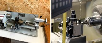
Turning
Numerically controlled machines designed for turning operations are characterized by an increased rigidity coefficient, which is ensured by weighted guides and spindles. This helps counteract the effects of torque during part machining and the associated increased load.
The kinematic scheme includes:
- Guides. Unlike milling-type equipment, the guides of lathes must be securely fastened; when installing them, even the smallest possible shift must be excluded.
- Lead screw. In lathes, the use of standard lead screws is ineffective, so devices with a CNC unit use reversible ball screws. Such parts ensure the replacement of sliding friction with rolling friction. The efficiency of this type of node reaches 90%. The advantages are: increased service life; reduced resistance to thorns; comparatively lower torque.
- Machine bed.
- Spindle and cutting tools.
Thus, the classic kinematic diagram of a universal lathe includes:
- Device frame.
- The headstock, which is assembled with a spindle assembly and a gearbox.
- Tailstock, which is designed to support the end of excess length workpieces and provide rigidity to the system.
- The apron where the control bodies are located.
- A support used to move the cutting tool relative to the fixed workpiece.
- Milling cutters.
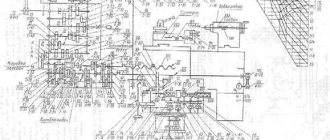
1.2. Kinematic diagram of a screw-cutting lathe 1k62
Fig.1.4. Kinematic diagram of a screw-cutting lathe 1K62
The main movement. The main movement in the machine is the rotation of the spindle, which it receives from electric motor 1 through a V-belt drive with pulleys 2-3 and a gearbox. A double-sided multi-disc friction clutch 97 is installed on the receiving shaft II. To obtain direct rotation of the spindle, the clutch 97 is shifted to the left and the rotation drive is carried out through the following chain of gears: 4-5 or 6-7, 8-9 or 10-11, or 12- 13, shaft /V, wheels 14-15, spindle V, or through a bust consisting of a group of gears with double-crown blocks 16-17 and 18-19 and gears 20 and 21. The last pair engages when block 15- is moved to the right 21 on the spindle. By switching the wheel blocks, you can get six options for gear engagement when transmitting rotation from shaft IV directly to the spindle, and 24 options when transmitting rotation through an overdrive. In reality, the number of spindle rotation speed values is less (23), since the gear ratios of some options are numerically the same. The spindle is reversed by moving the coupling 97 to the right. Then the rotation from shaft II to shaft III is transmitted through gears 22-23, 24-12 and further along the previous chain. The number of gearing options is 15, the actual values of rotation speeds are 12, since the gear ratios of some options are also numerically the same.
Feeding movement. The feed mechanism includes four kinematic chains: screw-cutting, longitudinal and transverse feed, and a chain of accelerated movements of the caliper. Rotation to shaft VIII is transmitted from spindle V through gears 25-26, and when cutting threads with an increased pitch - from shaft VI through the step increasing link and then through gears 27-28. In this case, the step increasing link can provide four gear options:
- spindle V, wheels 21-20, 29-19, 17-27-28, shaft VIII;
- spindle V, wheels 21-20, 29-19, 16-30, 27-28, shaft VIII;
- spindle V, wheels 21-20, 31-18, 17-27-28, shaft VIII;
- spindle V, wheels 21-20, 31-18, 16-30, 27-28, shaft VIII. From shaft VIII, movement is transmitted through a chain of wheels 32-33 or 34-35, or through a reversing mechanism with wheels 36-37-38, replaceable wheels 39-40 or 41-42 and an intermediate wheel 43 to shaft X. From here the movement can be transmitted via two options for gear engagement. Rotation is transmitted through gears 44-45-46 to shaft XI, then through wheels 47-48 and a ring wheel 49 to the gear cone of the Norton mechanism (wheels 50-56) and further along the chain of gears 57-58, 59-60, 61- 62 or 63-64 through wheels 65-66 or 64-67 - shaft XV. Rotation can then be transmitted to either the lead screw 68 or the lead shaft XVI. In the first case - through clutch 101, in the second - through a pair of 69-70 and overrunning clutch 106. From shaft X through clutch 98, i.e., when the external and internal gears 44-71 engage, rotation is transmitted to the Norton cone, which becomes the leading link, and then through wheels 49-48-47 to shaft XI and further, through coupling 100 to shaft XIII, and from the latter further along the chain of the first option.
Screw chain. When cutting threads, the caliper is fed from the lead screw 68 through the uterine nut fixed in the apron. For cutting metric and modular threads, the screw-cutting chain is installed according to the first option, and for inch and pitch threads - according to the second. Changing the thread pitch is achieved by switching the gears of the pitch increasing link, the Norton mechanism, blocks 61-63 and 67-66 and installing replacement wheels on the guitar. When turning and cutting metric and inch threads, replaceable gears 39-43-40 are in mesh, and when cutting modular and pitch threads - 41-43-42. In special cases, when cutting high-precision threads, to eliminate the influence of errors in the kinematic chain, the latter is shortened by including couplings 98, 99 and 101, as a result of which shafts X, XII and XV form, together with the lead screw 68, a single rigid connection. A screw-cutting chain for cutting threads with different pitches is adjusted in this case only by selecting replacement wheels on the guitar. Longitudinal and transverse feed of the caliper. To transmit the rotation of the apron mechanism, the running shaft XVI is used. A gear 72 slides along it along the keyway, transmitting rotation from shaft XVI through a pair of gears 73-74 and a worm pair 75-76 to shaft XVII. To obtain the longitudinal feed of the caliper and its reversal, one of the cam clutches - 102 or 103 is turned on. Then the rotation from shaft XVII is transmitted by gears 77-78-79 or 80-81 to shaft XVIII and then by a pair of 82-83 - to rack and pinion wheel 84. Since the rack 85 is fixedly connected to the machine bed, the rack wheel 84, rotating, simultaneously rolls along the rack and pulls the apron with the caliper. Transverse feed and its reversal are carried out by turning on clutches 104 or 105. In this case, through gears 77-78-86 or 80-87, rotation is transmitted to shaft XIX and then through gears 55-89-90 to screw 91, which imparts movement to the transverse support. Caliper rapid movement chain. To carry out the accelerated (installation) movement of the caliper, the running shaft XVI is given rapid rotation from the electric motor 92 through the V-belt drive 93-94. In this case, the caliper feed mechanism through the feed box does not need to be turned off, since an overrunning clutch 106 is installed in the drive chain of the drive shaft. Using screw pairs 95 and 96, you can manually move the cutting slide and the tailstock quill.
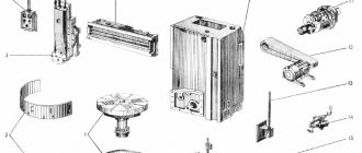
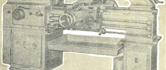
Headstock of screw-cutting lathe 1K62.
Headstock. In Fig. Figure 10 shows the headstock with gearbox. Rotation from the main electric motor is transmitted to a driven pulley sitting on shaft I. This shaft carries a reversible friction clutch, from which movement is transmitted to shaft II either through a block z = 56 - z = 51, or through a wheel z = 50 and an intermediate block z = 24 — z = 36, sitting on a cantilever axis. From shaft II to shaft III, rotation is transmitted through a triple block z = 47 - z = 55 - z = 38. In the left position of the block z = 43 - g = 52, sitting on the spindle, movement from shaft III is transmitted to the spindle directly through the wheels z = 65 - z = 43, and in the right position of this block - through a bust mounted on shafts IV and V. All shafts rotate on rolling bearings, which are lubricated both by splashing, since the gearbox is filled with oil, and by force - with the help pump The feed movement from spindle VI is transmitted to bit shaft VII and then to the feed mechanism.
Fig.1.5. Gearbox
studfiles.net