Relying on automation is not enough to keep equipment running safely and efficiently. Maintaining your lathe according to instructions will increase service life, increase productivity, and minimize the need for equipment repairs. Failure to comply with operating rules can lead to breakdown of the machine or disruption of its normal operation, as well as damage to workpieces and a decrease in the accuracy of work. To avoid this, it is enough to follow a number of simple rules, the implementation of which over time becomes automatic. What do you need to pay attention to in order to preserve equipment and produce quality products?
Maintenance of lathes
The lubrication system of a lathe is not simple: many friction pairs operate at different loads and speeds, and therefore require the use of different lubricants and methods of supply.
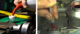
What kind of oil should I pour into the lathe and what should I use to lubricate the guides? Industrial oil I-20A flows into the oil tank, I-30A into the feed box and apron, and I-12A into the spindle head. To lubricate the guides, it is recommended to use oils with anti-jump additives.
During daily maintenance of the lathe, the oil level should be checked at all sight eyes and topped up if necessary.
General rules for caring for machines
Basic rules for caring for the machine before starting work:
- check the lubrication and cooling systems, the tension of the drive belts, the reliability of the tightening of the clamping elements, the serviceability of the control mechanisms, tools, auxiliary devices, protective guards, grounding and grounding devices;
- lubricate rubbing pairs that do not have a centralized oil supply;
- remove foreign objects from the work area.
Caring for the machine after the end of the shift:
- put tools, equipment, finished products and workpieces in the places designated for their storage;
- remove chips and dirt from surfaces and grooves;
- apply lubricant to the guides (the rules for caring for a lathe also include lubricating the quill, lead screw, tailstock screw, and lead roller with bearings).
Lathe installation
To install the machine, it is necessary to install a concrete foundation 30 days before operation. The calculation of the installation height of the lathe must be in accordance with the Operating Manual. If necessary, our company’s specialists will install the lathe on vibration supports.
The range of services for installation of a lathe also includes the following work:
- Assessment work at the installation site;
- Calculation of the foundation for a lathe;
- Drawing up installation drawings;
- Pouring the foundation for the machine;
- Leveling equipment with a level;
- Installing the lathe on the foundation.
Maintenance schedule
The maintenance schedule for CNC machines determines the time for scheduled maintenance of workshop or workshop equipment. The presence of such a document makes it possible to plan in advance the shutdown of equipment for preventive maintenance, and therefore to minimize possible downtime due to uncoordinated actions of machine operators, management and the lack of necessary specialists on hand in the event of a sudden malfunction of the equipment. To design a schedule, it is enough to use markers, the color of which is set for each type of maintenance, to mark the required dates on the wall calendar.
Changing the oil in a lathe
The service life of turning equipment largely depends on the proper functioning of the lubrication system of the units, the surface of which is in constant friction against each other. Timely lubrication prolongs the serviceability of machines, reduces their power consumption, reduces the load on parts, and reduces their wear. In addition, the use of high-quality lubricants has a positive effect on the quality of turning, efficiency, and allows maintaining the temperature of the units in a given range. Factors such as the health of the system and the choice of suitable oil are decisive.
Lubrication systems for lathe components
The operation of lubricating devices that deliver oil to the required point is based on the simplest laws of physics:
- Gravity, allowing oil to flow to the friction point on its own
- Capillary forces, which, through porous bushings and wicks, lift the lubricant to a certain height.
- The viscous friction force generated between the surface and the lubricant material itself prevents the latter from flowing down.
- Pressure. Used in manual lubrication systems such as piston pumps and oilers.
- Centrifugal forces causing oil to flow under pressure to surfaces.
- Inertia. Due to the capture of liquid by the rotating elements of the machine, its particles are scattered.
- The pressure difference that creates self-suction of oil through the mechanisms themselves.
Lubricant selection for guides
The best lubricant for guides is the one indicated in the equipment data sheet. If it is lost, you should choose what to lubricate the machine guides with, taking into account:
- their type;
- location in space;
- material of rubbing surfaces;
- operating temperature range.
To lubricate the horizontal sliding guides, anti-slip oils of ISO viscosity class 68 are used, and for vertical sliding guides, viscosity class 220 is used.
Which lubricant is best for rolling guides depends on the speed of operation and the degree of load - the lower the speed and the higher the load, the more viscous and dense the lubricant should be.
When deciding how to lubricate the linear guides of a machine, it is necessary to take into account the features of their design, movement speed, and specific workloads. Heavily loaded mechanisms require the use of high-viscosity extreme pressure lubricants, while high-speed ones require low-viscosity oils with improved anti-friction properties.
Mobil Vactra Oil series oils greatly facilitate the selection of lubricants for guides: they are suitable for any combination of materials of rubbing pairs.
Scheduled preventive maintenance
PPR (scheduled preventive maintenance) - implies all actions to maintain the operating power of the lathe. When caring for the equipment, its technical characteristics will correspond to those stated in the passport.
For each lathe, you need to draw up a schedule that will take into account the data stated in the passport and the features of the operating mode. The schedule must clearly indicate the intervals between maintenance work (lubrication, cleaning, oil control), replacement of unsuitable parts and the unit washing system.
Also, the equipment plan includes preventive, current and major repairs. Moreover, it is necessary to include both small and medium-sized ongoing work.
When should maintenance and repairs be carried out?
All manufacturers of turning equipment indicate the following work in terms of maintenance:
- Compliance with the rules for operating machine control mechanisms.
- Proper organization of the workplace with restrictions.
- Monitoring the cleanliness and integrity of the lubrication system and containers.
- Monitoring the oil level in equipment.
- Elimination of minor breakdowns.
- Adjustment of different machine systems.
All these duties do not require a separate day, they are carried out quickly and can be done during lunch breaks or when transferring work to another shift. It is better to readjust the lathe on a day off. If there is a specialist on staff with permission to set up equipment, then he can easily cope with such a task. If there is no such thing in the staff, then it is better to delegate the adjustment of equipment to the responsibilities of the repair and commissioning team.
Part of routine maintenance includes daily maintenance to clean and adjust the machine after the job is completed. If the enterprise operates in several shifts, it is recommended to carry out maintenance work every 8 hours.
It is also worth considering that in an enterprise that uses lathes and a shift work schedule, the staff must have a repair and commissioning team, which includes mechanics, lubricants, electricians, saddlers and mechanics. It is this team that will be responsible for the performance of the equipment and the quality of the products produced.
Types of machine maintenance
According to GOST 18322, machine maintenance is divided into the following types:
In production, equipment maintenance is usually divided into:
- routine (cleaning and lubrication of externally accessible components and mechanisms, control of heating of rubbing parts, etc.), which is the responsibility of the machine operator;
- scheduled (cleaning and lubrication of components and mechanisms that require disassembly, changing oil and filters, adjustment, adjustment) - it is performed by the mechanic service.
Basic methods for checking a lathe
When checking a lathe for accuracy, the main checks are the bed guides, spindle runout and lead screw.
The bed guides must be straight in the longitudinal direction. When worn, grooves, scratches, and sometimes nicks appear on them. Wear can be detected by superficial inspection and using measuring tools. To determine its value, install the test ruler 1 (Fig. 255) one by one on the guides 2, then determine the gap between their surfaces and the ruler in the light and measure with a feeler gauge.
The following wear of the frame is considered acceptable: with a center height of up to 300 mm - 0.02 mm over a length of 1000 mm; with center heights greater than 300 mm - 0.03 mm at the same length. For new or repaired machines, only a convexity of the bed, but not a concavity, is allowed by this amount.
The bed guides for the tailstock must be parallel to the carriage guides. Check the parallelism with an indicator mounted in the tool holder on the carriage (Fig. 256), which is moved along the frame; The indicator pin rests against the tailstock guide. The permissible deviation is up to 0.01 mm for machines with a center height of up to 200 mm and up to 0.02 mm for machines with a center height of more than 200 mm.
The horizontality of the frame guides is checked with a level, as shown in Fig. 257, moving ruler 2 with level 1 along the frame guides. The permissible deviation is 0.05 mm over a length of 1000 mm.
The spindle axis must be parallel to the bed guides in the vertical and horizontal planes. To check, insert a test mandrel into the conical hole of the spindle and check it with an indicator for the absence of runout along its entire length. Then the indicator is secured to the carriage and installed so that the indicator pin touches the mandrel, first in the vertical (Fig. 258, a) and then in the horizontal (Fig. 258, b) plane. With each installation, moving the carriage along the mandrel to a length of 300 mm, note the deviations of the indicator, which should not exceed 0.01 mm in the vertical plane for machines with a center height of up to 200 mm and 0.02 mm for machines with a center height of up to 400 mm. In the horizontal plane, indicator deviations should not be more than 0.01 mm for machines with any center height.
Deviation of the mandrel, counting to the right of the headstock, is allowed in the vertical plane only upward, and in the horizontal plane - only towards the cutter.
The spindle journals should rotate without wobbling. The spindle is checked for runout using an indicator mounted in the cutting head. When checking, it is necessary that the pin 1 of the indicator rests on the neck 2 of the spindle (Fig. 259, a). The permissible deviation is 0.01 mm for center heights of up to 350 mm and 0.02 mm for center heights of more than 350 mm.
The spindle must not have axial movement during rotation. The check is carried out as in the previous case, but the pin 1 of the indicator (Fig. 259, b) is pressed against the end of the collar 2 of the spindle. The permissible deviations are the same as when checking the journal runout.
The top of the front center should not have any runout when rotating. To check, the indicator is fixed in the cutting head (Fig. 259, c) and its pin 1 is pressed against the center cone 2. The permissible deviations are the same as in the previous two cases.
The pitch accuracy of the lead screw is checked using an accurate threaded mandrel 1, installed between the centers of the front and rear stock (Fig. 260), and an accurate cylindrical nut 2, screwed onto the threaded mandrel. The nut 2 has a longitudinal groove into which the ball of the holder 3, which carries the indicator 4 and is fixed in the machine support, is inserted. The tip of the indicator rests against the end of the nut, which is held from rotation by the ball of the holder. The machine is adjusted to the mandrel thread pitch. Having started the machine with the split nut turned on, monitor the indicator readings. Permissible deviations: 0.03 mm at a length of 100 mm and 0.05 mm at a length of 300 mm for machines with center heights up to 400 mm.
Practical testing of lathe accuracy. In addition to the geometric checks discussed, a comprehensive practical check of the accuracy of the lathe is carried out. The purpose of the test is to assess the accuracy of the machine in operation when manufacturing parts with cylindrical and end surfaces. During this check, the resulting deviations in ovality, taper and flatness are determined, which should not exceed the deviations established by GOST: ovality 0.01-0.02 mm and taper 0.02 mm over a length of 1000 mm and concavity of the end no more than 0 .02 mm on a diameter of 300 mm.
Repair of main components
bed
The 16K20 bed is a cast structure with stiffening ribs on which all other equipment of the lathe is mounted. On the top of the bed there are four longitudinal guides of the lathe: two flat and two prismatic. The positioning accuracy of the tailstock and caliper carriage, as well as the alignment of the front and rear stock, depends on the condition of their surfaces. The composition and procedure for performing the work is regulated by section 6.1 of the technical manual “Repair of a 16K20 screw-cutting lathe.”
There are four machining methods used to repair lathe guides:
- manual scraping;
- grinding using portable grinding equipment;
- grinding on surface grinding equipment;
- planing on a longitudinal planing machine;
https://youtube.com/watch?v=sJgzGG_6PU0
In general, if the wear is less than 15 microns per 1000 mm, the surface geometry is restored by manual scraping. If more, use machine tools or the spraying method.
Scraping is performed using hand tools, so its labor intensity is several times higher than with mechanized processing.
In addition, only non-hardened surfaces can be treated with this method. It is possible to scrape the bed of a lathe without dismantling the bed, therefore, along with manual grinding, this is the most common method of restoring guide surfaces.
Grinding of guides using portable grinding equipment installed on the bed is used in two cases: if it is impossible to deliver the bed to the repair shop and if the length of the bed is greater than the length of the grinding equipment table. The most effective way to restore bed guides is processing on grinding and longitudinal planing machines in repair shops or at specialized enterprises. It provides the highest precision and guarantees quality.
Bed for machine 16K20
Restoration of deep damage to the lathe bed is carried out by spraying brass or zinc, as well as filling it with babbitt. After filling the dents and potholes with metal, the surface of the guide is processed by grinding or scraping.
Carriage
In accordance with section 6.2 of the Technical Manual, repairing the slide carriage of a 16K20 screw-cutting lathe includes two technological operations:
- restoration of the lower guides associated with the bed guides;
- restoration of the transverse guides adjacent to the guides of the lower part of the caliper.
Before starting work, the carriage is installed on the exposed bed along with the rack and feed box. After this, clamping bars, an apron, a lead screw and a running shaft are mounted on the carriage, it is set for accuracy, measurements are taken and the engagement of the apron gear with the rack is checked.
Carriage for machine 16K20
Based on the results of control measurements, the degree of wear of the guide surfaces is determined and they are processed manually and mechanically until the standard straightness, flatness and parallelism are achieved. At the final stage, the accuracy of fit to the lathe bed is ensured by processing with a scraper and grinding devices.
Tailstock
According to section 6.7 of the Manual, the range of work for repairing the tailstock of a 16K20 lathe includes technological operations to restore the parameters of the following components:
- surfaces of the body mating with the surfaces of the plate;
- surfaces of the plate adjacent to the body and frame;
- hole for quill.
When restoring flat surfaces, scraping and grinding are used, and when processing quills, boring is used.
Grinding of flat surfaces of guides is carried out on a longitudinal grinding machine. Prismatic surfaces are brought to standard quality by scraping. Boring the hole for the quill is done in two ways: on the machine itself using a boring bar and with dismantling on a boring machine.
How is it repaired?
Optimal clearance values throughout the entire operating range of matings are achievable on medium-heavy and heavy-duty machines only by restoring the geometric parameters on a grinding machine and scraping.
Restoration and restoration of a lightweight, albeit obsolete, machine is quite accessible to the modern craftsman. Electronic controls eliminate the need for bulky pulleys, belts, gears and massive electric motors. Stepper motors solve the problem of driving calipers and lead screws. The geometry and rigidity of the calipers can be mastered by any tool shop.
Areas of application
The 1615 lathe is designed specifically for machining relatively small parts using high-speed cutting and carbide tools. Its functionality allows you to process not only metal workpieces, but also parts made of other materials. The capabilities of the presented equipment are expanded due to additional functions, such as cutting metric, inch, and modular threads.
Depending on the technical characteristics and parameters of a particular model, screw-cutting lathes 1615 are used at home for piece production. It is also allowed to operate them in industrial enterprises for the purpose of mass production.
What determines the maintenance period?
The frequency of maintenance is determined not only by the technical documentation of the equipment, but also by the type of material being processed, machine load, wear of parts, lubricant quality, type of processing, environmental conditions and room contamination. If, during inspection of the machine, there is a lack of lubrication on the moving parts or the equipment operates with difficulty, the machine should be put in order without waiting for the moment regulated by the technical passport.
Can compressed air be used when cleaning a CNC machine?
During daily maintenance of a CNC machine, it is important not only to perform the work efficiently, but also to apply as little effort as possible and spend as little precious working time as possible. Using a compressed air gun frees hard-to-reach areas of the CNC machine structure from dust and chips much faster, which allows cleaning to be done several times faster
However, manufacturers of CNC machines strongly discourage the use of compressed air during maintenance and cleaning, and there are several reasons for this:
- Dust and dirt, including that generated during the processing of MDF and lifted from the concrete floor, have good abrasive properties. By getting under high pressure jets of compressed air even into closed bearings of electric spindles, ball screws, linear guides and other mechanisms, abrasive dust significantly reduces their service life.
- Dust flying in a stream of compressed air can penetrate the electronic components of a CNC machine and settle on electrical contacts. After some time, the density of the layer of dust deposited on the contacts can reach a level at which the electronic device fails.
- Compressed air may contain drops of water, which, if they get on exposed metal parts of the machine, can cause corrosion, when interacting with the contacts of electrical switches and relay devices, they can cause oxidation, and if they penetrate inside complex electronic devices, they can cause a short circuit.
- The efficiency of dust collection with compressed air tends to zero, since lightweight fractions rise and hang in the air, and after some time settle on the surfaces of the CNC machine, on the floor, on workpieces, thereby making cleaning not only useless, but also inappropriate.
- Dust particles from wood chips and concrete floors raised into the air, entering a person’s lungs, are harmful to his health.
As a rule, when performing operations and maintenance of a CNC machine in the production of furniture and MDF facades, compressed air is used as the fastest and most effective way to clean work tables from chips and dust. To clean the remaining parts of the CNC machine using compressed air, you should follow some recommendations:
- You can only blow air on the milling spindle when the CNC machine is turned on. The fact is that modern spindles are connected to a compressed air system, which creates a high-pressure area inside them, thereby preventing dust from entering the bearings. Directing a jet of compressed air into the electrospindle shaft is prohibited.
- A chuck (mandrel) with any tool must first be installed in the quick tool change mechanism of the milling spindle.
- Near the location of bearings and electrical devices, a compressed air gun should be used at a maximum distance, sufficient only to blow off small loose fractions.
- It is prohibited to direct a jet of compressed air at the impellers of the spindle cooling systems or the electrical cabinet of the CNC machine.
- Before using a compressed air gun, you still need to use a vacuum cleaner, brush or cloth.
Thus, if these recommendations are followed, daily maintenance of the CNC machine will indeed be useful, including to ensure uninterrupted operation of the equipment and extend its service life.
Frequency and rules of maintenance, selection of oil and lubricant for metal-cutting machines
The main document defining the rules of care and frequency of maintenance is the machine passport. The points to be lubricated, the type and amount of lubricant for each of them are indicated in the lubrication card and table.
If operating conditions require changing the intervals between maintenance and/or using lubricants of other brands, the company’s chief mechanic service draws up its own maintenance cards.
Oils for metal-cutting machines must have high washing ability - small metal shavings and dust generated during the processing of workpieces accelerate the wear of rubbing pairs. Their viscosity is selected taking into account the speed of operation and the degree of load of the mechanisms.
Machine oils of the brands ZIC, Mobil, Mannol have excellent performance characteristics.
Oil coolants form a film that is difficult to remove on the surfaces of machine tools. The use of synthetic compounds reduces the time spent on equipment maintenance.
Current repair of the machine
Milling machine repair
Current repair of the machine
To maintain production equipment in good condition, it is necessary not only to perform maintenance, but also to carry out such activities as routine and major repairs. Both types of activities are fundamentally different from each other, both in the goals pursued and in the degree of labor intensity, the list of work performed and the budget (see “Types of machine repairs”).
Routine repair of a machine (aka operational) is a set of measures aimed at eliminating malfunctions and the consequences of wear of individual components and mechanisms. In most cases, such work does not require removal of the unit from production, but is carried out at the installation site or in the repair shops of the enterprise. Maintenance repairs are not planned in advance, since they are associated with unpredictable breakdowns. Accordingly, it is impossible to determine the volume of work and the costs for it.
Routine repair of a machine involves two methods of implementation - individual and aggregate. With an individual restoration option, all faulty components are removed from the car, restored and reinstalled. The aggregate repair method involves installing parts from the reserves of the exchange fund. As for damaged spare parts, they are repaired and then replenish the stock of the exchange fund. This method can significantly reduce equipment downtime.
During a major overhaul, a complete revision of the structure is carried out, which requires not only specially equipped areas, but also special qualifications of specialists. The unit is disassembled into its component parts, and after checking for suitability for use, the parts are divided into three groups - serviceable, repairable and non-repairable. After replacing worn-out components, the machine is assembled, tested and debugged.
Unlike current repairs, major repairs guarantee proper operation of all components for at least ten years. As for operational measures, in relation to a unit that has served for 15-20 years, they do not give confidence in “tomorrow”, since the general high wear and tear of the mechanisms will constantly make itself felt with failures in one place or another.
After a major overhaul, you can forget about all the problems associated with resource depletion for a long time. In addition, as a rule, such measures are accompanied by modernization of equipment, thanks to which design imperfections are eliminated and the operational parameters of the machine are improved.
In general, the overhaul returns the unit to the passport accuracy standards, thereby improving the quality of the products produced, and also increases the safety, productivity, and efficiency of the equipment. All this, together with the highest level of modernization, compared to the purchase of new machine tools, will reduce costs by at least half.
The design bureau of "Modernization of Industrial Equipment" in Kolomna accepts old and new generation machines, both domestic and foreign, for current and major repairs, +7,.
Source
How does the machine lubricate automatically?
Lubrication of a screw-cutting lathe, or rather its moving parts, must occur constantly during operation. The supply of lubricants to the rotor is indicated by the rotating disk on the spindle head. Its rotation should begin within a minute after starting the equipment. This time should be enough for the gear pump, connected by a belt drive to the main engine of the unit, to supply oil to the reservoir. The lubricant will reach the engine bearings and oil distribution trays through a strainer with a magnetic liner. The system is closed - flowing into the spindle head, the oil again enters the reservoir, where it is cleaned of debris by a filter and again ends up on the moving parts.
Intermittent movement or stopping of the disk indicating the flow of lubricant to the parts of the screw-cutting lathe indicates that the filter is clogged or there is not enough lubricant in the system. In this case, the machine must
- disable,
- cut off the power
- remove the filter,
- wash it with kerosene,
- check the lubricant level in the reservoir,
- add oil if necessary,
- insert the filter into place and start the unit.
How to remove the filter
The mesh filter consists of several elements. To get it out of the tank, which serves as the filter housing, you need to disconnect the hoses from it, unscrew the bottom nut, and remove the filters along with the plastic frame.
Scheduled maintenance with mandatory filter washing is carried out in accordance with the instructions in the technical data sheet of the equipment.
Maintenance of lathes
The lubrication system of a lathe is not simple: many friction pairs operate at different loads and speeds, and therefore require the use of different lubricants and methods of supply.
What kind of oil should I pour into the lathe and what should I use to lubricate the guides? Industrial oil I-20A flows into the oil tank, I-30A into the feed box and apron, and I-12A into the spindle head. To lubricate the guides, it is recommended to use oils with anti-jump additives.
During daily maintenance of the lathe, the oil level should be checked at all sight eyes and topped up if necessary.
Features of maintenance of other types of machines
Milling
When maintaining a vertical milling machine, you need to monitor the oil level in the circulation system and hydraulic system, and refill the oil nipples of the guide slide, table, milling head, and table lifting and moving screws two to three times a shift.
Laser
Maintenance of a laser machine consists not only of timely lubrication of rubbing pairs. In addition, you need:
- Before starting work, check whether the laser tube is completely filled with water, clean the reflectors and focusing lens from dirt, and check the optical trajectory;
- clean the linear guides and chiller every two weeks, change the water;
- If air pumping deteriorates, clean the corrugations and the hood from dust from the inside.
Bending
Gear or transmission oil with anti-corrosion additives is poured into bending machines, the viscosity of which depends on the ambient temperature. For example:
Bending machines installed outdoors require seasonal maintenance with the replacement of “summer” oil with “winter” oil or vice versa.
Before adding new oil to the bending machine, the tank and lines must be thoroughly cleaned.
Format-cutting
Maintenance of a formatting saw, like any other woodworking equipment, involves regular care of its external and internal surfaces - sawdust and dust accumulating on them are fire and explosion hazards.
When choosing what to lubricate the saw, give preference to compounds that prevent resin, dust, and shavings from adhering to the metal.
Drilling
During maintenance of the drilling machine, it is necessary to ensure that no lubricant gets on the contact surfaces of the spindle and chuck - this can lead to an accident.
Grinding
During daily maintenance of the grinding machine, it is necessary to thoroughly clean its surfaces from abrasive dust and remove sludge from the coolant settling tank, during routine maintenance, monitor the condition of the fine oil filter, and clean the tank and magnetic separator at least once every three months.
Rocking machine
Maintenance of the pumping machine is carried out twice a year in order to prepare for work in the autumn-winter and spring-summer periods, combined with scheduled repairs.
Screw-cutting lathe. Purpose, principle of operation.
Screw-cutting lathes are the most universal machines of the turning group and are used mainly in conditions of single and mass production.
The structural layout of the machines is almost the same.
Screw-cutting lathes are the most common category of metalworking turning equipment.
This equipment is designed to perform a variety of jobs.
These machines can be used to grind external cylindrical, conical and shaped surfaces, bore cylindrical, conical holes, process end surfaces, cut external and internal threads, drill, countersink and ream holes, cut off, trim and other operations.
To cut a thread with a tap and die, only the main movement is necessary, since the tool feeds by self-tightening.
Varieties and design features
There are actually a lot of machines and they perform all kinds of metal processing operations, but we will highlight the most famous types
Multi-incisor
Designed for processing complex parts made from pipes, shaped profiles or rods of different sections. Multi-cutter or multi-spindle machines are mainly used in batch production.
Performed operations:
- drilling;
- thread;
- turning;
- pruning;
- boring;
- countersinking;
- deployment.
Multi-cutting machines have high productivity due to the large area of the drive mechanism, rigidity of the structure, and the ability to perform several operations simultaneously.
Carousel
A group of machines for working with large-sized parts and workpieces. The parts processed on them are short in length, but have significant weight and diameter.
Features of carousel models:
- used for processing conical or cylindrical surfaces;
- grooves of various configurations are made;
- You can also do grinding, milling, trimming ends;
- thread cutting.
In addition to the basic elements of any lathe, this type has additional equipment:
- table with faceplate;
- racks for moving the traverse.
Backing
The machines are designed for processing the back surfaces of tool teeth. It can also be used to perform other turning operations. The backing machine is distinguished by its special support design. The part is backed up as follows:
- rotational movement of the part;
- reciprocating movement of the cutting tool towards the part.
Screw-cutting
The most common group of machines. Widely used in serial and individual production. Screw-cutting models can be found in workshops, schools, and in any industry. They are easy to operate and maintain.
REFERENCE! The screw-cutting lathe is a universal model for all kinds of processing of metal workpieces. It can be used to make various types of threads: modular, inch, metric.
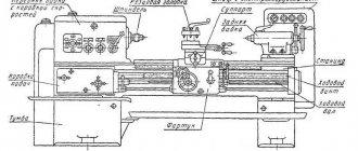
Structural elements:
- bed;
- front and rear stock;
- caliper;
- apron;
- gearbox.
Revolver
Revolver group machines are designed for processing parts from calibrated rods. Operations that can be performed on this equipment:
- turning;
- boring;
- shaped turning;
- countersinking;
- drilling;
- thread formation;
- deployment.
REFERENCE! The name of the machines in this group comes from a special holder. It can be driven or static. The drive type gives more possibilities for carrying out various operations.
Universal
Universal lathes include screw-cutting machines, since they can perform almost any metal operation.
Main technical characteristics of the universal machine:
- rotation speed (number of revolutions); accuracy class; it is indicated in the product labeling with the letters S, B, N, A, P;
- number of gears;
- what sizes of parts can be installed;
- weight and dimensions of the machine;
- the amount of feed and maximum movement along the axis.
Repair cost
The purpose of the overhaul is to restore the initial accuracy and safety of service of a machine with an expended resource. The cost of overhauling a lathe is usually less than 50% of its market value: for this reason, repairing it is cheaper than purchasing a new one. In addition, repairs are often ordered for original machines that are no longer in production or are made according to a special order.
Major repairs include:
inspection of equipment performance before disassembly;
- disassembly, washing, cleaning, troubleshooting of worn parts;
- grinding and restoration of the base surface;
- replacement of parts when repairing units if they cannot be restored;
- if necessary, replace or improve the electrical control system;
- galvanizing or painting parts, if they need to be processed in this way;
- assembly of a repaired machine;
- checking equipment for accuracy in accordance with specifications;
- checking operation at idle and under load;
- ultimately – commissioning.
In addition, the price for repairs depends on the type and type of turning equipment and the degree of wear of parts.
It is worth understanding that lathes are expensive equipment. Therefore, before you start repairing yourself, you need to weigh the pros and cons. If you lack experience, you can render it completely unusable.
Consequences of lack of service
Compliance with operating rules and qualified timely maintenance ensure uninterrupted operation of the CNC machine for a long time and accuracy of workpiece processing. Regular preventive measures make it possible to significantly reduce the risk of equipment failure, which entails downtime, repair costs and loss of profit due to supply disruptions.
- November 23, 2020
- 2703
Overview and diagrams of common models
Among the diverse model range and several generations of machines that are produced by our production, there are several models that continue to be popular for their technical characteristics and universal properties.
All of them are used in production or in domestic conditions to this day. At the same time, they continue to be worthy competitors to foreign analogues.
These are reliable, durable and durable devices capable of performing a huge number of different functions.
1L532
One of the most popular machines in the former USSR, which can successfully process workpieces of medium and large sizes.
At one time, this equipment was successfully exported to many countries around the world. Accuracy class – N. Machine weight – 43 tons.
16U04P
High precision equipment. The largest diameter of the part processed above the bed is 200 mm. Machine weight – 750 kg.
1P611
Lathe 1I611, used in production, including for turning wheels of railway vehicles. According to GOST, they are distinguished by increased accuracy and have the ability to brake the spindle. Device weight 560 kg. Easily performs the following functions:
- Drilling.
- Segment.
- Cutting internal and external threads.
- Treatment of various surfaces.
The largest diameter of the workpiece above the bed is 250 mm.
1D601
This machine is better suited for purely domestic use. The accuracy is lower than the previous machine. It features high performance even after many years of operation.
Moving the caliper is only possible manually. The weight of the entire machine is about 30 kg. Due to the small dimensions, the maximum length of the workpiece to be processed is 18 cm.
16K40
One of the most popular models that has really gained popularity among craftsmen. Belongs to the middle class of equipment with accuracy class N.
Since 1932, several tens of thousands of various screw-cutting lathes have been produced in the USSR. They were used not only in production, but also for training young people, in schools, colleges, and many had desktop machines in garages, homes, and their own workshops.
Specifications
| Characteristic name | Meaning |
| Main settings | |
| Accuracy class according to GOST 8-82 | N |
| Largest workpiece diameter over: | |
| bed, cm | 44.5 |
| caliper, cm | 22 |
| bed recess, cm | 62 |
| Maximum length: | |
| blanks, cm | 150 |
| turning, cm | 140 |
| Spindle parameters | |
| Diameter of through hole, cm | 5.4 |
| Direct rotation frequency, rpm | 10-1400 |
| Reverse rotation frequency, rpm | 16-1800 |
| Volume of the inner cone in the spindle | M5 |
| Spindle end according to GOST 12593-72 | 6K |
| Feed Options | |
| Maximum movement of the caliper carriage: | |
| longitudinal, cm | 140 |
| transverse, cm | 28 |
| Feed rate limits: | |
| longitudinal, mm/rev | 0,018…22,4 |
| transverse, mm/rev | 0,009…11,2 |
| Speed of fast movements of the caliper, longitudinal/transverse, cm/min | 400/2 |
| Longitudinal shift by one division: | |
| limb, mm | 1 |
| vernier, mm | 0.1 |
| Transverse movement of the caliper by one division of the dial, mm | 0.05 |
| Number of threads applied: | |
| metric | 36 |
| inch | 45 |
| modular | 36 |
| pitching | 45 |
| Overload fuse | present |
| Blocking longitudinal and transverse feeds | present |
| Switching longitudinal stops | present |
| Roughness of the part when grinding clean, microns, no more | Ra 2.0 |
| Tailstock parameters | |
| Maximum length of movement of the tailstock quill, cm | 15 |
| Maximum distance of movement of the tailstock, cm | ±1,5 |
| Parameters of built-in electrical equipment | |
| Number of electric motors on the machine | 3 |
| Main drive electric motor, kW | 7.5 |
| Drive of accelerated movements, kW | 0.75 |
| Cooling pump electric motor, kW | 0.12 |
| Overall dimensions and weight of the machine | |
| Machine dimensions (l ˣ w ˣ h), cm | 280 ˣ 119 ˣ 145 |
| Machine weight, t | 2.43 |