How can you use Arduino
A small board that has its own processor and memory, contacts - Arduino - is used in the process of designing electronic devices.
This is a kind of electronic constructor that interacts with the environment. Through contacts to the board you can connect light bulbs, sensors, motors, routers, magnetic locks to doors - anything that is powered by electricity. Arduino is effective for developing programmable devices that can do many things:
- plot the route of movement of the device (CNC machine);
- in partnership with Easydrivers, you can control the stepper motors of the machine;
- PC software can be implemented through this open programmable platform;
- connecting a Line Track Sensor to Arduino will allow you to track white lines on a dark background and vice versa;
- it is used to build a robot and various machine components;
- perform restriction of stepper motors (when traveling abroad).
Connecting stepper motors
For stepper motors we use an old USB cable because it has 4 wires inside and a cap, it is also more flexible and easy to work with.
Using the continuity mode on the multimeter, identify 2 coils, coil A and coil B.
I made 2 pairs of wire, choosing colors: one pair for spool A and one for spool B.
I soldered them and used heat shrink tubing.
Disassembling the drive
Laser level how to use lessons and training
This process must be performed with extreme caution. If handled carelessly, you can not only damage the device, but also harm your eyes.
The fact is that the laser can blind for some time and negatively affect visual acuity. Therefore, follow all the steps below slowly:
- Open the drive tray (the place where the disc is inserted).
- Turn the device over and unscrew the 4 screws located in the corners.
- Remove the cover.
- Turn the DVD drive over again.
- Remove the aluminum cover.
- Unscrew 2 screws under it.
- Disconnect the cables connecting the drive to the chassis (the one that moves the tray).
- On the chassis, unscrew the only screw on one side and three on the reverse.
- Carefully disassemble the product and remove the board with optical lenses and diodes.
- Remove the protection without making much effort (it looks like a small corner that needs to be turned).
- A diode will be detected.
- The “legs” of the diode (the place where it is attached) must be wrapped with wire - this is a kind of protection against static electricity.
- Using pliers, remove the diode.
- Use a small knife to pry up the diode and carefully remove it from the mount.
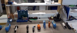
Required Tools
Laser plane builder. the red beam will help us!
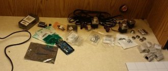
To make a laser, you will need certain components. All of them are sold in regular electronics stores, so you don’t have to put in any extra effort. So, for production you will need:
- Disk drive (DVD drive). You can use a faulty model, as long as the laser diode works.
- Soldering iron. Almost any one will do; more power is not required.
- Several small wires are necessary to connect parts to each other.
- Portable collimator (or regular laser pointer).
- 2 resistors with a resistance of 10 ohms.
- 3 AAA batteries (pinky batteries).
- 2 capacitors, one - 0.1 µF, the second - 100 µF.
- Pliers.
- A small screwdriver.
- Small knife.
- In some cases, an LM-317 chip may be required.
As you can see, making a laser from a DVD drive does not require any complex components.
Optics
The easiest way to make a homemade collimator is from a regular laser pointer. Even the cheapest Chinese option . All that is required is to take out the optical lens from the “laser” (it is very noticeable).
The beam width will be greater than 5 mm. Of course, such an indicator is considered very large and cannot claim to be a laser. The stock collimator lens will help reduce the diameter to 1 mm. True, to achieve such a result you will have to work hard. The main thing is not to rush and not to lose composure.
How to make an engraver from a DVD drive
How to choose a self-leveling laser level for home and renovation? rating of the best - review + photos and videos
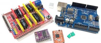
A DVD drive is used to make a laser engraver or CNC machine. To make a homemade tool, you will need:
- development board with USB cable;
- DVD or CD;
- plywood 6-10 mm thick;
- wood screws;
- laser module;
- joystick;
- computer power supply;
- semiconductor triodes TIP120 or TIP122;
- resistor 2200 Ohm;
- wires for connection;
- jigsaw;
- drill;
- wood drills 2, 3 and 4 mm;
- soldering iron;
- rosin;
- nuts and washers 4 mm;
- screw 4X20 mm.
The process of making a hand engraver is as follows.
- DVD or CD drives are disassembled by removing the internal mechanism.
- Remove the optics and mechanism board.
- Cut off the wire coming from the stepper motor. Wires are soldered in its place.
- A square with a side of 8 cm is cut out of plywood and glued to one of the drives.
- A plate on which the laser will be mounted is attached to another drive. Both plywood and plastic are suitable for this.
- The engraver body is made according to templates printed on a printer. The materials used are plywood or plastic. Holes are drilled in the workpieces into which self-tapping screws will be screwed.
- Holes are made in the resulting parts for fastening the drives. There are no exact markings, since the mechanisms come in different sizes and can be positioned in different ways.
- The blanks are connected with self-tapping screws, having previously drilled 2 mm holes so that the plywood does not crack. Plastic parts are connected with iron corners and screws.
- To add beauty to the appearance of the tool, the engraver is sanded and painted. You can use spray or acrylic paints.
- The pads are cut off from the power supply. The green and black wires are shorted. They twist or place a switch between them for convenience.
- Next, red, yellow and black wires are brought out to connect the load.
- The engraver is attached to the power supply using double-sided tape.
- A joystick and a button are attached to the debugging board, then the wires are brought out and attached to the plywood case.
- In order to correctly place the electrics, special diagrams are used.
- The laser is connected through transistors. To ensure that the laser is firmly attached, it is screwed to a plastic plate. First, the cooling radiator is attached, then the laser is inserted inside, which is then secured with screws. Next, this structure is attached to the engraver body.
- Then the software for Aurdino is downloaded. It is better to download a new version so that the mechanism works properly.
11photos
Also, creating an engraving machine from a DVD drive requires not only accuracy, but also electrical knowledge, as well as software awareness. After all, the normal operation of a CNC machine depends on the settings of programs with the help of which tasks are set for the engraver.
Build process
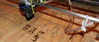
The homemade engraving machine of the proposed design is a shuttle-type device, one of the moving elements of which is responsible for movement along the Y axis, and the other two, connected to each other, for movement along the X axis. For the Z axis - which is also indicated in the parameters of such a 3D printer, the depth of burning of the processed material is taken. The depth of the holes into which the elements of the shuttle mechanism of the laser engraver are installed must be at least 12 mm.
Workbench frame - dimensions and tolerances
Photo-1 Photo-2 Photo-3 Photo-4 Photo-5 Photo-6
Aluminum rods with a diameter of at least 10 mm can serve as guide elements along which the working head of the laser engraving device will move. If aluminum rods cannot be found, steel guides of the same diameter can be used for these purposes. The need to use rods of this diameter is explained by the fact that in this case the working head of the laser engraving device will not go down.
Making a mobile cart
Photo-1 Photo-2 Photo-3
The surface of the rods that will be used as guide elements for the laser engraving device must be cleaned of factory grease and carefully sanded to obtain ideal smoothness. They should then be coated with a white lithium-based lubricant, which will improve the sliding process.
Housing assembly
Installation of stepper motors on the body of a homemade engraving device is done using sheet metal brackets. To make such a bracket, a sheet of metal approximately the width of the motor itself and twice as long as its base is bent at a right angle. On the surface of this bracket, where the base of the electric motor will be located, 6 holes are drilled, 4 of which are necessary for fixing the motor itself, and the other two are necessary for attaching the bracket to the body using standard self-supporting screws.
A suitably sized piece of sheet metal is also used to mount the drive mechanism, which consists of two pulleys, a washer and a bolt, on the motor shaft. To install such a device, a U-shaped profile is formed from sheet metal, in which holes are drilled for its attachment to the engraver body and exit from the motor shaft. The pulleys on which the timing belts will be mounted are mounted on the traction motor shaft and placed in the inner part of the U-shaped profile. Toothed belts, which are placed on the pulleys, must drive the shuttles of the engraving machine of the device; they are attached to the wooden base with self-tapping screws.
Installation of stepper motors
Photo-1 Photo-2 Photo-3 Photo-4 Photo-5 Photo-6
Final setup and preparation for work
Having made a laser engraving machine with your own hands and downloaded the necessary software into its control computer, do not start working right away: the equipment needs final configuration and adjustment. What is this adjustment? First of all, you need to make sure that the maximum movements of the machine's laser head along the X and Y axes coincide with the values obtained when converting the vector file. In addition, depending on the thickness of the material from which the workpiece is made, it is necessary to adjust the parameters of the current supplied to the laser head. This should be done in order not to burn through the product on the surface of which you want to engrave.
A very important and responsible process is fine tuning (adjustment) of the laser head. Alignment is needed to adjust the power and resolution of the beam produced by the laser head of your engraver. On expensive serial models of laser engraving machines, adjustment is performed using an additional low-power laser installed in the main working head. However, homemade engravers typically use inexpensive laser heads, so this method of fine-tuning the beam is not suitable for them.
Test your DIY laser engraver on simple drawings first
Sufficiently high-quality adjustment of a homemade laser engraver can be performed using an LED removed from a laser pointer. The LED wires are connected to a 3 V power source, and the LED itself is fixed to the working end of a standard laser. By alternately turning on and adjusting the position of the beams emanating from the test LED and the laser head, they achieve their alignment at one point. The convenience of using an LED from a laser pointer is that adjustment can be performed with its help without the risk of harm to both the hands and eyes of the operator of the engraving machine.
Laser wood engraver: necessary materials and step-by-step instructions
Making a homemade laser engraver for wood processing is quite simple. Enough hands and a little imagination. By the way, with the help of such a device it will be possible to apply inscriptions not only on a wooden surface, but also on a plastic or leather surface, for example, on a belt.
And, to keep things simple, it will not be powered by a battery, but by a regular computer via a USB cable. However, if you need to make your DIY wood engraving device portable, you can use a regular power bank.
Power bank can be used as a battery
To make it you will need:
- 2 cartridges of depleted caliber 8 mm and 7.62 mm shortened (starter or gas pistol and TT);
- laser LED (about 250-300 mW), which can be removed from an old DVD drive;
- target from the same unit;
- USB connector;
- brass tube with an internal diameter of 10 mm;
- 3 resistors with a total resistance of 30 Ohms;
- 50 Ohm resistor;
- thin threads;
- power button.
Of course, you can’t do it without a soldering iron, a drill, a power drill, and your favorite hot glue. When everything you need is ready, you can start working. And how to do this will be described in step-by-step instructions with photo examples and detailed explanations.
The most used tool for everything
The device of a laser engraver for home use and its operating principle
The basis of a laser printer is the optical system. At their core, these are heterogeneous lenses assembled together. Their task is to focus the light flux from a laser LED into the smallest point, amplifying it.
Also, the role of the transmission and control systems cannot be underestimated. The first includes servos that synchronize the laser with a given program. The latter, consisting of sensors and computing circuits, ensure error-free operation of equipment systems.
PHOTO: bing.comFactory-made laser engraver
The mechanical part consists of the main supporting parts and auxiliary mechanisms that make up the structure of the unit itself. And finally, cooling. Without this system of coolers and radiators, the laser would instantly overheat and burn out - it gets very hot during operation.
My laser option:
I also tried to make a laser from a DVD RW drive and I want to warn you right away that the idea is good, but it is quite difficult to implement. Disassembling a working DVD RW drive is stupid, and in broken drives, as a rule, the laser diode is already scorched and cannot be restored. Even if you managed to remove the working laser diode, be prepared for the fact that it requires a special collecting lens, since the laser diode itself does not shine focused. And to form the required beam divergence you will need good optics. Lenses from a DVD RW drive do not give the desired effect. I simply bought a ready-made laser module like HLDPM12-655-5 (in a housing with optics and polarity reversal protection), and connected it to a regular power supply.
Figure No. 6 – HLDPM12-655-5 appearance Figure No. 7 – HLDPM12-655-5 connected to the power supply Figure No. 8 – laser glow
The power of my laser diode is only 6 mW (this was enough for my purposes), but if you need to burn holes in a piece of paper, you will have to buy a much more powerful laser diode, which is correspondingly more expensive.
PS: I tried to clearly show and describe non-tricky tips. I hope that at least something is useful to you. But this is not everything that can be imagined, so go ahead and study the site
- Do-it-yourself thermal jigsaw For figured cutting in low-melting sheet materials, it is convenient to use this…
- Adjustable power supply based on voltage stabilizer LM317 A novice radio amateur simply cannot do without at least the simplest unit...
- Do-it-yourself ladder If you need to get to some object that weighs…
- Thyristor brightness control for a table lamp Despite the fact that incandescent lamps are an endangered species :)…
- Do-it-yourself workplace In rural areas, the workplace can be placed in a barn,…
Homemade tool for cutting and processing plywood
Considering the high cost of factory equipment, more and more people are trying to make a plywood laser cutting machine with their own hands. However, before embarking on such a procedure, make sure that you have certain skills and are willing to invest a lot of time and effort into the task ahead.
When manufacturing laser equipment, a number of features should be taken into account:
Determine the power indicators of the future car. It is no secret that at the stage of creating a system it is necessary to use special expensive devices with high power ratings, so the total cost of the final model is at least $600.- Find the right batteries and cooling. As mentioned above, to cool the gas moving through the pipe, it is necessary to use water and a pump that will pump it to the most vulnerable components of the system. For normal operation, the machine requires at least 100 liters of fluid.
- Therefore, it is necessary to fine-tune all elements of the laser system. To perform such an action, you must have at least minimal experience and spend a lot of time. This suggests that sometimes it is much easier to purchase a ready-made invention than to try to create it yourself, but everything is ambiguous.
Laser cutting of plywood sheets remains a complex process, but with the right approach it can create real works of art and intricate patterns.
Materials and tools
| Paragraph | Provider | Quantity |
| NEMA 23 stepper motor + driver | eBay (seller: primopal_motor) | 2 |
| Diameter 16mm, pitch 5mm, ball screw 400mm long (Taiwanese) | eBay (seller: silvers-123) | 2 |
| 16mm BK12 support with ball screw (drive end) | eBay (seller: silvers-123) | 2 |
| 16mm BF12 Ball Screw Support (No Driven End) | eBay (seller: silvers-123) | 2 |
| 16 shaft 500 mm long | (seller: silvers-123) | 4 |
| (SK16) 16 shaft support (SK16) | (seller: silvers-123) | 8 |
| 16 linear bearing (SC16LUU) | eBay (seller: silvers-123) | 4 |
| eBay (seller: silvers-123) | 2 | |
| Shaft holder 12 mm (SK12) | (seller: silvers-123) | 2 |
| A4 size 4.5mm clear acrylic sheet | eBay (seller: acrylicsonline) | 4 |
| Aluminum Flat Rod 100mm x 300mm x 3mm | eBay (seller: willymetals) | 3 |
| 50mm x 50mm 2.1m Aluminum Fence | Any theme store | 3 |
| Aluminum Flat Rod | Any theme store | 1 |
| Aluminum corner | Any theme store | 1 |
| Aluminum corner 25mm x 25mm x 1m x 1.4mm | Any theme store | 1 |
| M5 socket head screws (various lengths) | boltsnutsscrewsonline.com | |
| M5 nuts | boltsnutsscrewsonline.com | |
| M5 washers | boltsnutsscrewsonline.com |
Basics of assembling an engraver on Arduino
To begin with, I suggest you look at what the whole process of creating an engraver with a radio amateur looked like:
Powerful stepper motors also need drivers to get the most out of them. In this project, a special stepper driver is taken for each motor.
Here are some details of the selected components:
- Stepper motor - 2 pcs.
- Chassis dimensions are NEMA 23.
- Torque is 1.8 lb-ft at 255 oz.
- 200 steps / revolutions - 1 step is 1.8 degrees.
- Current strength - up to 3.0 A.
- Weight - 1.05 kg.
- 4-wire bipolar connection.
- Stepper driver - 2 pcs.
- Step digital drive.
- Chip.
- Output current: 0.5A to 5.6A
- Output current limiter: reduces the risk of motors overheating.
- Control signals: “Step” and “Direction” inputs.
- Pulse input frequency - up to 200 kHz.
- Supply voltage - 20 V - 50 V DC.
For each axis, the motor directly drives the ball screw through the motor connector. The engines are mounted to the frame using two aluminum angles and one aluminum plate. The corners and aluminum plate are 3mm thick and strong enough to support a motor (1kg) without bending.
Setting up and preparing for work
When the mechanism is completely assembled, it needs to be configured and prepared. To operate the engraving machine, you need to configure the software. Thanks to its use, an image is formed.
Setting up and checking operation should be carried out exclusively with special glasses designed to protect the eyes. Even if the laser beam is not focused enough, it has the property of damaging the retina if it hits a person’s eyes. It is also recommended to wear glasses when observing the engraving. The diameter and depth of the resulting recesses depends on the power level of the laser beam and the time it takes to complete the work.
If everything is done correctly, then when you turn on the power and change the position of the joystick, movement should occur. If the joystick moves to the right/left, then the laser should move; if the joystick moves in the forward/backward direction, then the table begins to move.
The laser beam is focused using a sheet of paper. It is necessary to rotate the lens until the laser dot is at its minimum size. Or it is possible to burn the sheet. This means that it is in this position that the beam focus is maximum.
In order for the engraver to receive the necessary image, it is worth using a programming environment called Processing. You need to download it from the official website and install it on your computer. The image must be black and white and size 300*300.
Engraving using a focused laser beam involves heating the material being processed. The result is a contrasting image.
The image obtained in this way is quite durable and resistant to all kinds of physical and chemical influences from the outside.
You will see how to make a laser engraver from DVD drives with your own hands in the next video.
Design and principle of operation
The main element of the engraver is a semiconductor laser. It emits a focused and very bright beam of light that burns through the material being processed. By adjusting the radiation power, you can change the depth and speed of burning.
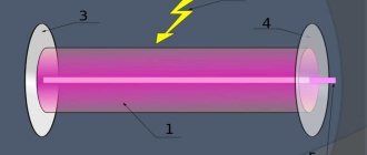
The laser diode is based on a semiconductor crystal, on top and bottom of which there are P and N regions. Electrodes are connected to them, through which current is supplied. Between these regions there is a P-N junction.
Compared to a regular laser diode, it looks like a giant: its crystal can be examined in detail with the naked eye.
The values can be deciphered as follows:
- P (positive) area.
- P - N junction.
- N (negative) area.
The ends of the crystal are polished to perfection, so it works as an optical resonator. Electrons, flowing from a positively charged region to a negative one, excite photons in the P-N junction. Reflecting from the walls of the crystal, each photon generates two similar ones, which, in turn, also divide, and so on ad infinitum. The chain reaction occurring in a semiconductor laser crystal is called the pumping process. The more energy supplied to the crystal, the more it is pumped into the laser beam. In theory, you can saturate it indefinitely, but in practice everything is different.
During operation, the diode heats up and must be cooled. If you constantly increase the power supplied to the crystal, sooner or later there will come a time when the cooling system can no longer cope with heat removal and the diode will burn out.
The power of laser diodes usually does not exceed 50 Watts. Above this value, it becomes difficult to make an effective cooling system, so high-power diodes are extremely expensive to produce.
There are semiconductor lasers with 10 or more kilowatts, but they are all composite. Their optical resonator is pumped by low-power diodes, the number of which can reach several hundred.
Compound lasers are not used in engravers because their power is too high.
Creating a laser engraver
For simple work, such as burning patterns on wood, complex and expensive devices are not needed. A homemade laser engraver powered by a battery will be sufficient.
Before making an engraver, you need to prepare the following parts for its assembly:
- Laser diode from a DVD-RW drive.
- Focusing lens.
- Aluminum U-shaped profile or non-ferrous metal tube with an internal diameter of 15-20 mm.
- Electrolytic capacitor 50 V, 2200 µF.
- Resistor 5 Ohm.
- Film capacitor 100 nF.
- Tact button.
- Switch.
- Thermally conductive adhesive.
- 18650 battery and holder for it.
- Shoe sponge box.
- Scotch tape, including double-sided tape.
- Hot glue gun with consumables.
- Charge controller.
- Jack 2.1 x 5.5 mm.
Remove the write head from the DVD drive.
Carefully remove the focusing lens and disassemble the head housing until you see 2 lasers hidden in heat-distributing casings.
One of them is infrared, for reading information from the disk. The second one, red, is the one who writes. In order to distinguish them, apply a voltage of 3 volts to their terminals.
Pinout:
Be sure to wear dark glasses before testing. Never test the laser by looking at the diode window. You only need to look at the reflection of the beam.
You need to select the laser that lights up. You can throw away the rest if you don’t know where to use it. To protect against static, solder all leads of the diode together and set it aside. Saw off a 15 cm section from the profile. Drill a hole in it for the clock button. Make cutouts in the box for the profile, charging socket and switch.
The schematic diagram of a DIY DVD laser engraver looks like this:
Using wires to pins B+ and B- of the charge controller, solder the battery compartment. Contacts + and - go to the socket, the remaining 2 go to the laser diode. First, solder the laser power supply circuit by surface mounting and insulate it well with tape.
Make sure that the terminals of the radio components do not short circuit with each other. Solder a laser diode and a button to the power supply circuit. Place the assembled device in the profile and glue the laser with heat-conducting glue. Secure the remaining parts with double-sided tape. Reinstall the tact button.
Insert the profile into the box, bring out the wires and secure it with hot glue. Solder the switch and install it. Do the same procedure with the charging socket. Using a hot glue gun, glue the battery compartment and charge controller into place. Insert the battery into the holder and close the box with the lid.
Before using it, you need to set up the laser. To do this, place a sheet of paper 10 centimeters from it, which will be a target for the laser beam. Place the focusing lens in front of the diode. By moving it further and closer, achieve a burn through the target. Glue the lens to the profile in the place where the greatest effect was achieved.
The assembled engraver is perfect for small jobs and entertainment purposes such as lighting matches and burning balloons.
Remember that the engraver is not a toy and should not be given to children. The laser beam causes irreversible consequences if it comes into contact with the eyes, so keep the device out of the reach of children.
CNC device manufacturing
For large volumes of work, a conventional engraver will not cope with the load. If you are going to use it frequently and a lot, you will need a CNC device.
Assembling the interior
You can even make a laser engraver at home. To do this, you need to remove the stepper motors and guides from the printer. They will drive the laser.
The complete list of required parts is as follows:
- Laser diode from a writing drive.
- Radiator for diode.
- 3 stepper motors.
- 6 round guides.
- Fastenings for guides.
- 3 double or 6 single sliding carriages.
- Power supply 5 V, 4 A.
- Arduino UNO.
- 2 stepper motor drivers.
- 2 switches.
- Sheet of metal 50 x 50 cm and 2 mm thick (for the base).
- Large sheet of plywood.
- Corners for fastening plywood.
- Self-tapping screws.
- 2 furniture hinges.
- Wires with a cross section of 0.5 mm².
- Movable cable channel.
- Plastic cable ties.
- Transistor IRFZ44.
- 2 pressure rollers.
- 5 gears.
- Metal rod (axle for gears and rollers).
- 4 bearings.
- Toothed belt.
- 2 A step-down DC-DC converter.
- Four limit switches.
- Tact button.
- Jack 2.1 x 5.5 mm.
- 4 rubber or silicone feet.
- Thermally conductive adhesive.
- Epoxy resin with hardener.
Connection diagram for all components:
View from above:
Explanation of symbols:
- Semiconductor laser with heatsink.
- Carriage.
- X-axis guides.
- Pressure rollers.
- Stepper motor.
- Drive gear.
- Toothed belt.
- Guide fastenings.
- Gears.
- Stepper motors.
- Sheet metal base.
- Y axis guides.
- X-axis carriages.
- Toothed belts.
- Mounting supports.
- Limit switches.
Measure the length of the guides and divide them into two groups. The first will contain 4 short ones, the second - 2 long ones. Guides from the same group must be the same length.
Add 10 centimeters to the length of each group of guides and cut the base to the resulting dimensions. Bend U-shaped supports for fastenings from scraps and weld them to the base. Mark and drill holes for the bolts.
Drill a hole in the radiator and glue the laser in there using heat-conducting glue. Solder the wires and transistor to it. Bolt the radiator to the carriage.
Install the guide rail mounts onto the two supports and secure them with bolts. Insert the Y-axis guides into the mounts, put the X-axis carriages on their free ends. Insert the remaining guides with the laser head installed on them. Place the fasteners on the Y-axis guides and screw them to the supports.
Drill holes in the places where the electric motors and gear axles are mounted. Reinstall the stepper motors and place the drive gears on their shafts. Insert pre-cut axles from a metal rod into the holes and secure them with epoxy glue. After it hardens, place the gears and pressure rollers with bearings inserted into them onto the axles.
Install the timing belts as shown in the diagram. Pull them tight before fastening. Check the mobility of the X-axis and laser head. They should move with little effort, rotating all the rollers and gears through the belts.
Connect wires to the laser, motors and end switches and tie them together with zip ties. Place the resulting bundles in movable cable channels and secure them to the carriages.
Lead the ends of the wires out.
Laser module from DVD-RW drive
I want to warn you right away that I am not responsible for your actions! You do everything at your own peril and risk!
The other day I made a laser module for my homemade CNC machine and here I’ll tell you how to make it yourself.
Some people don't believe it, but you can actually light matches with a laser from a DVD drive,
cut thin film or burn on plastic and wood.
So what we need:
- The first thing I took out was the radiator. Since the laser gets very hot during operation, it needs somewhere to put its heat.
- I used a heatsink from an old Asus motherboard. Something like this:
Next we need the laser itself. It can be found in DVD-RW drives, but others will not work.
- The drive speed must be more than 16x. So far I have made a working module and ruined about 5 disk drives!
- So I advise you to be very careful. The last donor was the NEC-7173 disk drive.
- We disassemble the drive, take out the laser head, it looks something like this:
We find the required laser, there are 2 of them (CD & DVD). We need the one with a larger radiator:
As a last resort, you can experimentally determine which of them is DVD by applying voltage to them, the CD will shine dimly, and the desired one will shine brightly.
ATTENTION! DO NOT Aim the LASER AT YOUR EYES! LOSE YOUR VISION! But don’t rush to connect the laser just yet; a special driver is needed to power it. I advise you to cut the cable going to the laser before removing the laser, and not unsolder it immediately
I advise you to cut the cable going to the laser before removing the laser, and not unsolder it immediately.
You can unsolder it only when you have closed all the laser contacts with a wire, because... he is afraid of static electricity.
This is what the laser looks like when removed from the radiator:
This is what a laser looks like in its original radiator: And this is what my laser looks like:
I did not remove my laser from the original radiator.
After removing the laser, let's start assembling the driver.
- For power supply, as I already said, you need a special driver.
- The laser must be supplied with a certain current, not voltage.
I propose one of the simplest schemes:
We are assembling this circuit, but we are not connecting it to the laser yet. Install a radiator on LM317!
Let's put it all together. First, we drill a hole for the wires to the laser, then for the bolts securing the laser, and for attaching the lens.
Where required, we cut the thread. We make a bar that will press the laser itself. Look at the photo for more details:
I think it’s clear why I didn’t remove it from the original radiator; I simply pressed it against the larger radiator with a bar.
For better conductivity, I lubricated it with thermal paste. When soldering wires, do not remove the wire that closes the laser contacts before connecting to the driver.
We take the lens from the same laser head, the top one, which looks at the disk. I secured it to a PCB bush.
We don’t put fingerprints on it or smear it with glue! The lens is afraid of glue vapors at the moment. Let's look at the photo:
We install, turn on the laser through the driver, and adjust the lens to get the minimum point.
I get a point at a distance of 1 cm to the part and about 2 mm of the lens to the laser.
Well, here’s a photo of the finished module in operation on a CNC machine:
Second life for old drives
Many are interested in the secondary use of components of equipment with a status of obsolete. There are already interesting publications on Internet resources about where to find uses for old CD or DVD drives.
One of the craftsmen made his own CNC machine from a DVD-Rom, although a CD-ROM is also suitable for control. Everything that is available is used. The machine is intended for the manufacture of printed circuit boards in electronics and milling and engraving of small workpieces. The sequence of work can be formulated as follows:
- You will need three DVD drives for precise positioning in order to move the coordinate machine along three axes. The drives must be disassembled and unnecessary elements removed. Only the stepper motor along with the sliding mechanism should remain on the chassis.
IMPORTANT! The disassembled drive chassis must be metal, not plastic.
- Since the DVD motor is bipolar, it is enough to ring both windings with a tester to determine their purpose.
- Some people doubt whether the motor has enough power or whether the working unit has moved the required distance? To reduce engine forces, it is important to decide that the table will be movable and not a portal type.
- The base of the bed is 13.5x17 cm, and the height of the bars for the vertical stand of the machine is 24 cm. Although DVD drives from manufacturers may differ in size.
- Next, you need to take the stepper motors to solder the control wires (it doesn’t matter - these will be motor contacts or a cable cable).
- Since connection with screws is not acceptable here, wooden rectangles (future platforms) that will move along three axes must be glued to the moving parts of the engine.
- The spindle will be an electric motor with two screw clamps. It must be extremely light, otherwise it will be difficult for CD/DVD mechanisms to lift it.
Homemade laser engraver for working with large areas
Any drawing for assembling the so-called KIT kits from the same Chinese friends is taken as a basis. Finding an aluminum profile is not a problem; making carriages with wheels is also not a problem. A ready-made laser module is installed on one of them, the other pair of carriages will move the guide truss. The movement is set by stepper motors, the torque is transmitted using toothed belts. It is better to assemble the structure inside a box with active ventilation. The acrid smoke released during engraving is harmful to health. When used indoors, exhaust to the street is required.
Important! When operating a laser of this power, safety precautions must be observed.
If you are working with metal plates, the reflected glare from the beam can damage the retina. The best protection will be red plexiglass. This will neutralize the blue laser beam and allow you to monitor the process in real time. The control circuit is assembled on any programmable controller. The most popular systems are Arduino UNO, sold on the same Chinese electronics websites. The solution is inexpensive, but effective and almost universal. The most common option is connecting to a personal computer. The creation of a design and engraving parameters takes place using any standard graphics editor.
Important! It should be remembered that most Arduino-based controllers only work with vector images.
If your image is raster, you should trace it.
By connecting and programming the USB controller, you will be able to output an engraving task directly from digital media (flash drive), having previously created a file on the computer. Result:
A laser head engraving machine is so affordable that it can be purchased not only for commercial use but also for personal use.
Making crafts for children, saving on advertising materials for your own company, design items for your home - this is an incomplete list of uses for the machine.
A self-made installation will delight you at minimal cost.
DIY laser engraver from a DVD drive - video instructions
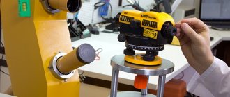
Laser for metal engraving and how the device works
There is no point in describing in words how to make a laser engraver with your own hands from an Arduino Uno or a 3D printer. It will be much more instructive to see everything with your own eyes. We invite you to see how to make a similar CNC laser engraver.
Watch this video on YouTube
After all, even a photograph can be engraved on a laser machine of this type by launching the desired program. Many people ask how to prepare a photo for engraving on a laser machine. It's simple: the photo is scanned and uploaded into the program.
Photogravure on metal
Step by step guide
First step
To make a laser level with our own hands, we need, and perhaps most importantly, the emitter itself with a cross, into which two small prisms are already built-in, responsible for projecting a horizontal and vertical line.
Second step
We need to find or create a mechanism similar to a pendulum. You can take the insides of an old joystick, as shown in the video below, or assemble it yourself from metal, plastic or wooden parts, the main thing is that all connections move freely relative to each other.
You can see the structure of the pendulum using a real laser plane builder in the photo:
Third step
Next, we install our module into the pendulum; to do this, we make a corresponding hole in the lower part of the pendulum with a diameter the same as the thickness of the module.
When our conditional compensator is assembled, we need to make weights that will help us in setting up a homemade laser level.
Fourth step
We make two holes in the pendulum barrel, namely transverse and longitudinal, for the subsequent installation of threaded studs on both sides.
You need to screw two or three nuts onto all four resulting ends, depending on the weight from which the pendulum will react to the overweight.
Thus, we have a device in which we can shift the center of gravity, and, accordingly, the position of the laser lines.
Fifth step
We take a battery compartment from some old toy for 3 or 4 batteries, two will not be enough, so our homemade laser level will quickly run out, and more than four will be heavy.
It is advisable to make the compartment through a switch, it will be much more convenient. The switch can also be taken from an old unnecessary toy, fortunately this goodness is now in bulk.
Sixth step
Our entire self-assembled device needs to be installed in some kind of housing, here you can take, for example, a part of a plastic plumbing pipe with a diameter of 110 mm with a plug.
Screw the homemade compensator to the lid and insert it into the pipe, but first you need to cut apertures (windows) for laser beams.
Seventh step setup
When the entire assembly of the laser level with your own hands is completed, it needs to be configured. For precise adjustment, you can use a cheap water level, which we make two marks on the wall at a distance from each other, about 5-6 meters.
Using these two points we check the horizontal; if it passes evenly through these points, then no adjustment is required. When the laser line deviates from a given line, we use our nuts on studs, moving which will change the position of the laser plane.
The vertical line can be checked using a simple plumb line.
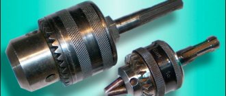
The procedure for calculating the resolution of a stepper motor dvd drive
To measure the resolution of a CD/DVD drive stepper motor, you need a digital micrometer. The distance along the screw has already been measured. The total length of the screw was measured using a micrometer, which turned out to be 51.56 mm. Next, you need to determine the lead value, which is the distance between two adjacent threads on the screw. Threads were designed for 12 threads within this distance. Retraction = distance between adjacent threads = (total length / number of threads = 51.56 mm) / 12 = 4.29 mm / rev. The pitch angle is 18 degrees, which corresponds to 20 steps/revolution. Now that all the necessary information is available, the resolution of the stepper motor can be calculated as shown above: Resolution = (Distance between adjacent threads) / (N steps / revolution) = (4.29 mm / revolution) / (20 steps / revolution) = 0.214mm/step. Which is 3 times better than the required resolution, which is 0.68 mm/step.
Making a drill from a blender
Kitchen appliances are often used to make various tools. You can make an electric engraver yourself at home. For this you will need:
- blender;
- jaw chuck with key;
- jaw chuck attachment;
- file.
The manufacturing process consists of several stages.
- First, the blender body is disassembled. Then remove the factory nozzle and cut off part of the body. Then turn on the blender and grind the diameter of the working part to the desired size. To do this, use a flat file for metal work.
- After this, the body is reassembled. Then attach the attachment to the blender shaft. The jaw chuck is secured to it using screws.
Power supply
Some of the work is done. Now the homemade device must be provided with electric current. The power supply of a standard diode should be 3V, and the flow rate should be up to 400 mA. These values may vary depending on how fast the disk is written.
There are 2 ways of eating, each of which has advantages and disadvantages. However, each one is powered by a battery(s).
First option
A distinctive feature of the first method is voltage regulation using a resistor. The laser does not require high power. So, the components of a drive with a write speed of 16X will need 200 mA. You can increase this value to a maximum of 300 mA, otherwise there is a possibility of damaging the crystal and forgetting about the homemade laser. The main advantages of this method are the reliability of the product and ease of manufacture. The main disadvantage is possible problems with the placement of batteries.
Second way
It will be more difficult to create a laser using this option. In addition, the finished device is more suitable for stationary placement. The point is the driver (LM-317 chip), which is a board for creating a certain power, as well as limiting the electric current.
As you can see in the diagram, to create a laser you will need:
- Directly, the LM-317 chip.
- 2 resistors at 10 ohms.
- 1 variable resistor per 100 Ohm.
- 1 diode
- 100 µF capacitor.
Regardless of the environment as well as the power source, the driver will maintain 7V power.
DIY linear laser from a pointer
Hello, dear readers and DIYers! In this article, the author of the YouTube channel “jisaku-kobo” will tell you how to make a very useful device for your home and workshop from an ordinary laser module or pointer.
This simple design will allow you to turn a point laser into a linear one.
With its help it will be possible to make linear indicators for various machines, which will greatly facilitate the work. Materials. — Aluminum tube with an outer diameter of 8 mm and a wall thickness of 1 mm — Profile aluminum pipe 10X10 mm, wall thickness 1 mm — Laser module — Plastic bolts — Holder for two AA batteries — Heat-shrinkable tube, solder — Two-component epoxy resin — Glass round rod with a diameter of 3 -5 mm - Masking tape - Two AA batteries.
Tools used by the author. — Soldering iron — Small circular saw or hacksaw — Clamp — Flathead and Phillips screwdrivers — Drilling machine — Square — Tap — Diamond needle file.
Manufacturing process. So, the author purchased a laser module with a wavelength of 580 nm and a battery compartment.
Now the master leans the glass tube against the end of the pointer, and instead of a dot, a very clearly visible, bright line is obtained.
He will make the housing for the laser and glass lens from a 10X10 mm aluminum profile pipe.
And here is a drawing of the body itself. Drills holes for a glass rod and an M3 clamping bolt
It is very important to make the holes for the lens strictly coaxial
Cuts an M3 thread for a bolt with a tap.
On a miniature circular saw, he extends the cutting disc slightly, sets a stop along the length of the workpiece, and secures it with a clamp.
Holding the lens with a napkin, inserts it into place in the body.
To improve, the author needs an aluminum tube 8 mm in diameter, and the same square profile 10X10 mm.
Inserts it into the body, clamps the laser and the head with bolts.
Thanks to the author for a simple but useful device for the workshop and home!
Good mood, good luck, and interesting ideas to everyone!
Source
Become the author of the site, publish your own articles, descriptions of homemade products and pay for the text. Read more here.