To prepare for setting up the thickness planer, it is necessary to carry out a preparatory operation - lower the support rollers (8) below the table level (10). The thicknesser table is lowered so that a rectangular planed wooden block laid on it passes freely under the planing knife shaft. The thicknesser table with a wooden block laid on it rises until it touches the knife shaft (at the same time, the planer shaft slowly moves back and forth).
When the upper edge of the block touches the knife shaft, the digital value of the table position is recorded.
The table lowers by 0.3 mm. The measuring block moves behind the planing shaft under the rear clamp (3). The height of the clamp is set with adjusting screws (2) until it touches the bar.
The table is lowered by 0.7 mm (which will be 1 mm from the initial position of the table) and the measuring block is moved under the front clamp (5). The adjusting screws (6) adjust the height of the front clamp until it touches the bar. Then the table is lowered another 0.5 mm (this will be 1.5 mm from the initial position of the table) and the rear pressure roller (1) is adjusted until it touches the block.
The table is lowered by 0.5 mm and the height of the grooved input feed roller is adjusted using a measuring block.
The table is lowered another 1 mm and the measuring block moves under the claw guard. Its height is adjusted until it touches the measuring bar.
Then the exit of the support rollers is installed above the table surface.
When working with coniferous species, the height is set to about 0.3 mm, with deciduous species about 0.1 mm.
Depending on the thicknesser model, the adjustment dimensions may differ slightly from those given above. The diagram below shows the dimensions for adjusting the thickness planer CP 6-9, CP 8-1
And the dimensions for adjusting the surface planer CP6-10, CP8-2 are shown in Figure 9.
In conclusion, we can propose an alternative method for setting up thicknessing machines. Its peculiarity lies in the elimination of a number of intermediate operations to change the position of the table. Namely:
Preparatory operations for setting up are carried out according to the method described above (The thicknesser table is lowered so that a rectangular planed wooden block laid on it passes freely under the planing knife shaft.
The thicknesser table with a wooden block laid on it rises until it touches the knife shaft (at the same time, the planer shaft slowly moves back and forth).
The peculiarity is that instead of a short block, a planed strip is used, running from the input rollers to the output rollers. In this case, at the moment the rack touches the knife shaft, all adjustable components (feed and receiving rollers, front and rear clamps, claw protection) will already be on the rack and, moreover, will be raised by this bar relative to the adjustable stops. Using measuring probes, the position of all components can be adjusted without additional table movements.
So for the surface planer SR-3-6 these dimensions will be
0.3 mm between the adjusting screw and the rear clamp support (3).
1 mm between the adjusting screw and the front clamp support (5).
1.5 mm between the adjusting screw and the rear pressure roller support (1).
If you encounter any difficulties in setting up, please contact our specialists by phone, we are always happy to provide assistance:
- 8
- 8
Maintenance of a thicknessing machine - cleaning, replacing knives, setting up
Show Control Panel
- Published: Jan 27, 2021
- In this video we show routine maintenance of a thickness planer in our carpentry workshop. At the end of the video we’ll show you the flyer, which helped us significantly increase productivity and quality. As a bonus, there are two more small modernizations of the Soviet thickness planer. You will learn: how to clean the surface planer parts, replace the knives and align the shafts so that they are parallel. 0:00 Maintenance of the thickness planer 0:23 Upper access to the shafts 1:00 The order of the shafts in the machine 1:14 Cleaning the shafts 2:20 Cleaning the table 2:52 Checking the geometry of the machine before replacing knives 4:33 Replacing knives using magnetic devices 5: 14 The second method of replacing knives without magnetic devices 6:18 Adjusting the shafts 7:05 Life hack: how to double productivity 7:52 Improvement: replacing the ruler on the surface planer 8:33 Important. Balancing the knife shaft. Timely maintenance and correct adjustment increases the service life of the product. And most importantly, it improves the quality of products. What is a surface planer - in simple words, it is a machine that makes the upper and lower parts of the workpiece parallel.
Planer settings
The principle of operation of the thickness planer is based on the methodology of flat planing of boards. The main working tool of a thickness planer is the knife shaft. Workpieces for processing are fed onto a horizontal work table manually or by rollers, which press them against the table and pull them into the processing area. The material is planed from above with knives, and as a result, parts are obtained that are almost identical in size. Many thicknessing machines have an automatic system for feeding workpieces at a certain speed in order to neatly and accurately remove the strictly required layer.
Today you can buy a single-sided or double-sided surface planer. The first ones have one blade shaft. In double-sided models there is also an additional knife shaft on the work table. Before processing parts with a surface planer, they must already be planed in a jointer. In design, in principle, the two machines are very similar to each other. Often, a double-sided thicknesser and a jointer are combined into one mechanism. Such equipment has two tables - for a jointer on top, and also for a surface planer at the bottom.
Traditionally, workpieces with a length slightly larger than the distance formed between the feed rollers are planed on a thicknesser, as in the video about a thicknesser. In the case of using backing templates (tsulagi), you can plan workpieces (boards, bars, boards) with non-parallel opposite edges on a surface planer. The surface of this template must be tilted in such a way that during the horizontal planing procedure of products the required taper can be obtained.
In some models of thicknessing machines, for user convenience, manufacturers have increased the length of the table. That is why the timber has a significant support area, and the products are processed much more accurately. In order for the workpiece to slide normally on the table, special grooves are made in them to reduce the friction force. Similar models were previously used mainly in production, but at the moment these principles are being widely introduced into amateur thicknessing units.
One of the main advantages of a thickness planer is the high quality of processed surfaces. The thickness of the resulting parts is set using a lifting mechanism when the table moves upward in relation to the knife shaft. But it is worth considering that with a high cutting speed of workpieces, as well as a relatively large cutting depth, the quality of the machined surface deteriorates. That is why, in order to achieve a smooth surface, it is necessary to make finishing passes at a shallow depth and at a low speed of rotation of the knife shaft, unless, of course, the machine provides adjustment.
The thickness planer is one of the particularly high-performance woodworking machines. It is worth adjusting the dimensions of the workpiece being processed once using a ruler and a lift, and the entire batch of products will be identical, within the permissible limit. On thicknessing machines you can process parts with a width of up to 1250 millimeters and a thickness of 5 - 160 millimeters, except for special machines designed for strictly defined types of work.
About setting up a thickness planer
Thicknessing machines must be carefully adjusted before work. In fact, any adjustment inaccuracy will cause processing defects or lead to a decrease in the efficiency of the machine. Most often, the following omissions in setting up thickness gauges are observed:
Distortion on the desktop.
The planed surface will not be parallel to the planed side.
The grooved roller is located very low and presses too hard on the surface of the parts at a shallow planing depth.
Planed surfaces are obtained with transverse dents.
The lower feed rollers are placed above the table level higher than necessary, by 0.1-0.2 millimeters.
As a result, the workpiece vibrates under the impacts of the knives, and thinner parts bend. Planing is not straight and not so smooth; the ends of the products are more exposed.
The rear pressure block presses on the workpiece.
For this reason, the product stops as it exits the front feed rollers due to the reduction in feed force. Since the knives will continue to rotate, one place is planed on the surface of the part, as a result, a groove appears here across the entire width of the planing.
In general, grooves are formed during any, even the shortest, stop of the product. Stoppages occur quite often while parts are entering the rear rollers. This happens when the upper rear roller is placed very low, as well as when it puts too much pressure on the material. The reasons for a short-term delay or stopping of a part are: insufficient pressure on the product of the feed rollers, the location of the lower rollers is too high, severe clogging of the table when processing pine parts with resin.
Chips get under the rear smooth roller due to improper installation of the cap or exhauster malfunctions.
For these reasons, dents appear on the planed surface, sometimes delaying the part.
That is why, when setting up a thickness planer, it is necessary to remember that when the table is significantly filled, for example, when planing a wide board or simultaneously feeding products across the entire width of the work table, the pressure of the feed rollers must be increased, since in these cases the cutting resistance increases significantly. When planing narrow parts or when the table is small, it is necessary to reduce the pressure of the feed rollers in order to avoid crushing the wood.
Finally…
Particularly common in the woodworking business are jointing, milling, planing and thicknessing machines, which are intended for planar, volumetric and profile milling of straight and curved workpieces made of solid wood and wood materials, for cutting lugs and tenons in the bars of door frames, window blocks. If you plan to engage only in planar planing, then you should definitely give preference to a thickness planer.
Comments • 13
Hello, what bearings for the knife shaft are best to buy, brand, accuracy class?
How do you lubricate the feed rollers and the cutting shaft bearings?
Instead of a ruler, try installing a DRO (digital display device. In carpentry, especially for high-quality production of stairs, parts are made with an accuracy of 0.1 mm. And you are happy with the new ruler. The machine, of course, too. Of course, it’s a pity for those who are trying to make at least something with such scrap metal I've been making stairs for thirty years now.
6:54 minutes, a little further from your finger there is an adjustment of the table relative to the knife shaft. Even if you didn’t set the knives exactly, with this adjustment you ensure that 2 slats on both edges are planed to zero. I tried it, it works great. There's a small move there.
Source
Setting knives on a thickness planer
Thicknessing machines can often be found at manufacturing enterprises engaged in wood processing and manufacturing of products from it. The operating principle of the machine is based on flat planing of a wooden workpiece of a given thickness, so surface planers are most often used for final processing of the surface of the workpiece. Thickness control is achieved due to the upper location of the knife shaft, the height of which is adjustable within an acceptable range. High-quality completion of a task is very important in production. Before we figure out how to set up thicknessing machines, let's talk a little about their structure and types.
Method of setting a thicknesser (thicknessing machine)
When the upper edge of the block touches the knife shaft, the digital value of the table position is recorded. The table lowers by 0.3 mm. The measuring block moves behind the planing shaft under the rear clamp (3). The height of the clamp is set with adjusting screws (2) until it touches the bar.
The table is lowered by 0.7 mm (which will be 1 mm from the initial position of the table) and the measuring block is moved under the front clamp (5). The adjusting screws (6) adjust the height of the front clamp until it touches the bar. Then the table is lowered another 0.5 mm (this will be 1.5 mm from the initial position of the table) and the rear pressure roller (1) is adjusted until it touches the block.
The table is lowered by 0.5 mm and the height of the grooved input feed roller is adjusted using a measuring block.
The table is lowered another 1 mm and the measuring block moves under the claw guard. Its height is adjusted until it touches the measuring bar.
Then the exit of the support rollers is installed above the table surface.
When working with coniferous species, the height is set to about 0.3 mm, with deciduous species about 0.1 mm. Depending on the thicknesser model, the adjustment dimensions may differ slightly from those given above.
The diagram below shows the dimensions for adjusting the thickness planer CP 6-9, CP 8-1
And the dimensions for adjusting the surface planer CP6-10, CP8-2 are shown in Figure 9.
For the thickness planer CP3-5, the manufacturer gives the following adjustment dimensions
Setting up thicknessing machines for wood processing
Setting up thicknessing machines consists of correctly installing the feed roller clamps and support rollers relative to the knife shaft.
Adjustment is carried out with screws, which serve as limiters for the height of the rollers above the table. In this case, you should ensure that each roller touches the top edge of the template. The pressure of the feed rollers is adjusted by rotating the nuts, compressing or loosening the spring. It must be taken into account that when the spring is strongly compressed, the rollers will crush the wood and marks will remain on the processing surface from the grooves of the front roller. Therefore, you should not overcompress the spring. At the same time, the pressure must be sufficient to prevent the rollers from slipping relative to the workpiece. The spring pressure is selected depending on the humidity and type of wood being processed. When processing wet wood or hardwood, the pressure should be greater, and when processing dry and soft wood, less pressure.
The support rollers are set in height so that their generatrix is parallel to the working surface of the table. Non-parallelism of the rollers is eliminated by moving their supports in the grooves with screws and controlled with a straight edge. The ruler is placed on support rollers, and the gap between its lower edge and the working surface of the table is measured with feeler gauges. Control is carried out at the edges of the table. Non-parallelism of the rollers to the table is allowed no more than 0.1 mm over a length of 1000 mm.
The size of the roller protrusions above the table is selected depending on the type of wood being processed. Thus, for soft rocks the protrusion of the rollers is 0.2 - 0.3 mm, for hard rocks - 0.1 -0.2 mm. If there is an adjustment mechanism, the support rollers can be adjusted in height by turning the handle through a system of rods and eccentric rollers. The amount of protrusion of the rollers is controlled on a scale.
To adjust the machine to a given thickness of the workpiece, it is necessary to unlock the table, move it in height and secure it in the working position by turning the handle or switching the batch switch. The table height is adjusted manually by rotating the table lifting handwheel or by pressing the “Up” or “Down” button. When moving the table, you must first turn off the knife shaft drive with the “Stop” button located on the control panel. A mechanical drive is used to quickly bring the table to a given position for large movements, and the final installation is done manually.
The adjustment mechanism for thicknessing machines is equipped with two
reporting devices: for rough tuning and final fine tuning. The coarse adjustment measuring device includes a measuring ruler and a pointer, which are mounted on a frame and a movable table. The final fine adjustment is carried out using a dial (graduation value 0.1 mm) attached to the handwheel for manual movement of the table
When setting up a machine by processing test parts, the table is installed at a distance approximately equal to the largest nominal size.
After dimensional adjustment and adjustment, you should carefully inspect the moving parts of the machine and let it idle. Then you need to make sure that all machine mechanisms are working without failure and process test workpieces, after which you need to take control measurements of the thickness of the part in three sections along the length (at the ends and in the middle). The roughness of the treated surface is determined visually.
The processing mode on the machine is determined depending on the type of wood, the width of the milling, the thickness of the layer being removed and the required surface quality. The feed speed is selected according to the schedule and set using a handle on a scale.
Working on machines. Before starting work, check the correct installation of the knives and the sharpness of their sharpening. The knife shaft must be protected. It is not allowed to process workpieces whose length is less than the distance between the front and rear shafts. It is prohibited to clean, adjust or repair the machine while it is running.
The thicknesser machine is operated by two workers. The machine operator places the jointed workpiece on the machine table and moves it forward under the upper feed roller. After gripping with the roller, it is necessary to prepare the next workpiece and direct it to the front end at the end of the previous one, eliminating, if possible, inter-end gaps. If the machine is equipped with a sectional roller and the feed speed is low, then several workpieces can be fed simultaneously, using the entire width of the table
You cannot feed workpieces whose thickness difference is greater than the permissible values (2-3 mm), since thin workpieces may be ejected back from the machine or processing defects may occur. It is also prohibited to process workpieces shorter than the minimum length specified in the operating manual for this machine.
if you have any questions? call or write @dvt-spb.ru we will definitely help you!
We recommend reading
- The main reasons for equipment failure are: violation of operating rules, including overloading of individual mechanisms and components; violation of the regulation of a specific unit or mechanism
- Various ways to set up thickness gauges are described, both according to the instructions and a simplified method. To prepare for setting up a thickness planer, it is necessary to carry out a preparatory operation.
- The order (sequence) of operations when setting up a jointer (jointer) is described. Why can’t you carry out adjustments until the main faults have been eliminated? The procedure for simple and complete setup of the machine is listed.
Pages: [1] 2 3 … 11 DownAuthor Topic: Aligning knives on the jointer and other adjustments of the jointer/thicknesser (Read 148087 times)0 Users and 1 Guest are viewing this topic. Good day, forum members. Let me make a reservation right away: I searched through the search engine, but didn’t find anything. That's why I'm opening a new topic. I came across this problem when replacing knives on a jointer. It turns out to be very accurate, but it takes a very long time, and if it’s fast, there is a deviation. I'll try to describe my thoughts on this matter. At the moment I know only 2 ways to align knives: a) using a ruler, b) using a device with magnets (there is one!). I didn’t really like the device (maybe my hands weren’t sharpened for it). Here's the thing. According to the instructions, this contraption is used simply: you attach these magnets to the old knives in the drum, fix them, then replace the knives with sharp ones, and the adjustment seemed simple - you attach magnets that set the protrusion of the knives. It would seem that everything is simple, except for a few “buts”. When sharp knives are in the grooves and magnets are attached, it is necessary to tighten the clamps that are located in the grooves. The clamps are fixed in height with bolts (3 pieces - on the left, right and in the middle) and in width with bolts (4 pieces - on the left, right and 2 in the middle). The problem is this: when you tighten the vertical bolts, it would seem that you have tightened them to the desired position (the end of the bolt rests on the bottom of the groove under the knife). But when you remove the magnet, this same bolt can easily “pull” the knife a little from its fixed position. In connection with the problems described above, I use a ruler - The knife is positioned so that when scrolling the shaft, the knife extends the ruler by 4-6mm (the distance being equal on both the left and the right). But here’s the problem - it’s difficult to find an ideal ruler, since their evenness differs slightly, say by 0.02mm. In addition, when you measure yourself, you can easily deviate by 0.1-0.2 mm, and accordingly, when jointing on a surface planer, the left and right sides of a wide board/board will differ by 0.1 mm-0.2 mm (i.e., not ideal and will have to smooth out these joints using a grinder). I don’t understand what to do, please tell me! Recorded by Andrey, I understand that everyone on the forum knows what kind of jointer you have. In this regard, there is no need to even name the company and model. Please: Brand, model, scan from a manual or catalog - the exhibiting process. Well, a photo wouldn't hurt. The fact is that the design of fastening knives on shafts may differ, even if the knives themselves are unified. Recorded by now everything will be... sorry for not indicating Recorded by
An accuracy of 0.1-0.15 mm for installing knives is considered sufficient.
If everything is that much, congratulations! It is normal for this difference to reach 0.3 mm. The reason is the specific distribution of pressure from the ripples across the width of the workpiece.
In theory, the knives should be set in height, not the wedges.
When setting up, these screws must first be tightened so that the knives move easily between them and the wall of the groove, and at the same time do not dangle. Having aligned the knife with such a tightening along the reach, they begin working tightening with the same force of all screws - first the outer / center ones half-strength, then finally again in this sequence. Recorded by If a problem has a solution, then there is no need to worry; if there is no solution, then there is no point in worrying. This is the whole principle of not giving a damn. I won't be able to take a photo yet, because... Yesterday I planed - the knives are not dull, which means there is no need to touch them. But on the weekend I will need to lubricate the rubber drum with lithol (in the groove where it sits), otherwise when I replaced it I still didn’t lubricate it, but now sometimes the creaking is loud. It would be necessary to lubricate it, otherwise again something will have to be ordered from spare parts. Recorded by
The trick is this - the knives have grooves, and there are 2 grooves on the wedge. When changing the knife, you release the wedge and pull the shaft out of its groove. Then you place the knives on the tenons/grooves. That is, it turns out that the knife only moves left and right (i.e. along) the wedge, but tightly across (or almost). Next, you carefully insert the wedge with the knives into the groove and begin to work magic with the bolts. Today I’ll take a photo of the bolts and post them, because you don’t need to remove the knives for this. Alex21 - i.e. Is everything ok with the adjustment? But then what about magnetic devices? As far as I understand, they should speed up the process of setting up knives, but I still don’t understand how this happens! after all, if you use them, then when testing “with a ruler in relation to the output table” you get discrepancies (i.e. inaccuracies) that are much greater than what you can show with a ruler! It’s kind of strange, because these devices don’t cost a lot of money, but I didn’t find any use in them! Recorded by
Sorry - 2 conditional spikes (if you can call them that). Recorded by
These are protective spikes to prevent knives from flying out. In theory, they should not have anything to do with configuration. Good - it turns out that you have a knife block + wedge set in height - it doesn’t matter.
IMHO the skill is lacking. There are two main tricks here: to catch the same tension so that the knives move easily during the initial exhibition and do not dangle, and the second is to not warp the knife when tightening. Recorded by If a problem has a solution, then there is no need to worry; if there is no solution, then there is no point in worrying. This is the whole principle of not giving a damn.
This is usually the hardest part about installing planer knives. Both on a thicknesser and on a planing machine. Recorded by
can you provide more details if possible? I'll have to take a photo to make it clearer where my problem is. Recorded by
Probably not. This must be shown so that you can touch it with your own hands. Recorded by If a problem has a solution, then there is no need to worry; if there is no solution, then there is no point in worrying. This is the whole principle of not giving a damn. heh... Recorded by I have a question, I think this goes here, I have a combined machine: jointer + circular saw + chisel, it’s homemade but made to last, but here’s what’s tormenting me: I can’t adjust the jointer in any way (maybe there’s something wrong with the plates (steel 700*450*10), they seem level, or maybe the knives (shaft for 3 knives 400 mm) lined up, planed cleanly and the problem itself is: when planing, I get a “ski”, this can be seen on workpieces about one and a half meters long; when joining two boards, a gap of approx. 0.7 mm, on short workpieces of 60 cm this is practically not the case, so what should I do about it? I apologize for the confusion, but I wrote it as I understand it, so what needs to be clarified? Recorded by “Now, guys, we must definitely blow. Because if you don’t blow, a miracle won’t happen!” © Hmayak Hakobyan Recorded by Pages: [1] 2 3 … 11 Up |
Setting up and dimensional adjustment of a thickness planer
The causes of machining errors are: geometric inaccuracy of the machine and its wear; inaccuracy of cutting tools, clamping and installation devices; insufficient rigidity of the machine-tool-workpiece system; errors when setting up the machine. Precise operation of the equipment is ensured by careful adjustment and dimensional adjustment.
Setup is a set of labor techniques performed for the purpose of regulating and coordinating all assembly units of equipment, establishing processing modes, test running of equipment and monitoring the resulting products. A distinction is made between initial machine setup (at the end of installation of a new machine or after repair) and current setup (during operation). The machine operator usually deals with ongoing setup - resetting the machine for processing workpieces of a different shape and size.
The content of the current setup includes: checking the suitability of cutting tools; cleaning the machine from chips; removal of protective devices; inspecting moving elements for defects and performing minor repairs if necessary; monitoring the presence of lubricant in mechanisms and on guides, troubleshooting problems in the lubricant supply system; readjustment of the machine according to the specified size and shape of the workpieces and subsequent inspection of the machine for the absence of visible faults (loose elements, guards, etc.); testing the machine at idle speed, identifying and eliminating detected faults; trial processing (for example, milling workpieces with thickness measurements); adjustment of the machine based on the results of control measurements and repeated trial processing with product measurements.
The readjustment is considered completed in full if the machine provides the required accuracy and quality of processing at the set feed rate.
Adjustment of single-sided thickness planers. When setting up thicknessing machines, it is necessary to correctly install the clamps, feed rollers and support rollers relative to the knife shaft. The installation of clamps and feed fingers is carried out according to a template or a control ruler. The template is placed on the table. The support rollers must first be lowered below the working surface of the table. The table is raised until the upper working edge of the template comes into contact with the blade of the knife when turning the knife shaft manually.
Memorize the height position of the table using the readout device of the adjustment mechanism. The table is lowered by 0.3 mm. Adjust the position of the rear clamp with the set screws and ensure that the lower edge of the clamp touches the upper edge of the template. The table is lowered another 0.7 mm (1 mm from the original position) and the position of the front clamp (chip breaker) is adjusted with screws. Lower the table again by 0.5. 1 mm (1.5. 2 mm) from the original position) and change the position of the rear and front feed rollers.
Adjustment is carried out with screws, which serve as limiters for the height of the rollers above the table. Make sure each roller touches the top edge of the template. The pressure of the feed rollers is adjusted by rotating the nuts, compressing or loosening the spring. Do not compress too much; spring, since the rollers will crush the wood and the grooved front roller will leave marks on the processing surface. However, the pressure must be sufficient to prevent the rollers from slipping relative to the workpiece. The spring pressure is selected depending on the humidity and type of wood being processed. When processing hard wood, the pressure should be greater, soft wood - less.
Where and why is a marking thicknesser used?
The tool is used for work by carpenters, joiners, mechanics, and welders. The design of the device for metal and wood is different, but has a similar principle.
Using a marking thicknesser, you can make markings for further execution:
- Tenons, grooves.
- Bending sheet metal edges.
- Dissolution of boards and metal products.
- Drilling in line, etc.
Depending on the length of the arm of the marking thicknesser, it can be used to draw a parallel line relative to the edge of the workpiece at different distances, but usually no more than 30 cm. In this case, it will be very even with the same distance. However, to do this, you need to move the tool slowly, as it is possible to make a technical error and cause bending.
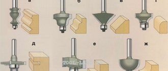
Planer device
The appearance of the marking thicknesser may vary. Moreover, almost all instruments have the same design. The most common of them consists of only 4 parts:
- Barbell.
- Sliding thrust block.
- Fixing screw or wedge clamp.
- Hairpin or needle.
The largest part of the tool is the rod. This can be a profile rail made of wood or metal. Also used as a steel rod. Often the bar has markings similar to those on a ruler. This makes it easier to adjust the tool before marking.
A thrust block slides along the surface of the rod. It is clamped to the guide with a screw. In a more simplified version, a wedge is used instead of the latter. By pushing it in or out, you can block or wedge the block. A pin or needle protrudes from one edge of the rod. This is the contact part of the device, which causes a marking mark in the form of a scratch.
The essence of using a thicknesser is that it rests against the edges of the part with a sliding block, after which it is pressed tightly against the edge and held parallel. As a result, the pin causes a visible scratch. By changing the position of the block, you can adjust where the line is drawn.
The tool's capabilities are limited by the length of the rod. In most cases, purchased thicknesser samples are not capable of drawing a parallel line further than 30 cm from the edge of the part. There are more massive instruments, but it is physically more difficult to work with them, especially alone.
Advantages of a thickness planer, and why it is better than other marking tools
A marking thicknesser is the most convenient and popular tool in its field of use. If the part has straight edges, then neither a ruler nor a square can handle the markings better or faster.
Its advantages include:
- A very thin, clearly visible marking line.
- The line turns out smooth, with the same depth along the entire length.
- When working with wood, the tool does not tear the fibers, even across them.
- Markings from a thicknesser on wood can be used to position a chisel or hacksaw.
When using a thicknesser, you do not need to measure the indentation with a ruler while marking each workpiece. The tool works as a template, which is very convenient when making parts of the same type. There are tasks that cannot be performed at all with other devices. For example, if you need to draw a line parallel to the edge of a curved part. In this case, the roller marking thicknesser will be able to carry out even markings.
Types of surface planers
Although a marking thicknesser is a very simple tool, its design has been adapted to various specific uses. As a result, several varieties of it appeared. Among them are:
- Regular, with one stud.
- Nesting, with two needles.
- With two rods.
- Drawing.
- Roller.
The usual one with one pin is the most common version of this device. It can be purchased at any store that sells carpentry and plumbing tools. Often it is simply made with your own hands from a strip and a piece of handle.
nested has an almost similar design . With its help, two lines are drawn at once. This variation of the tool is used for marking for the production of tenons and grooves. The lines are drawn directly along the edge, as well as along narrow bars and slats. The needles of such a tool are fixed not in sockets, but in cuts. Due to this, it becomes possible to move them apart and bring them together, changing the gap between them. That is, if necessary, you can install one pin to make regular markings.
You can make such markings with a regular classic surface planer. You just have to do it 2 times. First, the first line is drawn, then the bar is moved and the second is drawn.
Thicknesser with two rods , like the previous one, can simultaneously mark 2 lines. In this case, the distance between them can be anything, within the capabilities of the tool. Its use speeds up marking by 2 times. The rods are removable. If only one is needed for a certain job, then the second one can be omitted. The constructive installation of a wide gap between the studs makes it possible to draw parallels not only along the edges, but also the front part of the board or metal product.
The drawer can be regular or with two rods. Its peculiarity is that instead of a pin, a pen, pencil or writing rod is inserted into it. As a result, it draws the markings rather than scratching them. It makes the line wider. It cannot be used to position the chisel, but it is clearly visible. When a marker is installed in the tool, it can make marks even on very hard steel, which is almost not scratched by a regular pin. Writing thicknessers are good if you need to make a cut along their line, as they are clearly visible.
The roller marking thicknesser differs from the classic design, but it works on the same principle. In it, the role of a rod is usually performed by a steel rod. The sliding block is made in the form of a disk with an extension for a screw. The marking part is a roller attached directly to the end of the rod. The principle of its operation is very similar to a glass cutter. The advantage of this tool is that due to rotation, even if it is blunt, it does not undermine the wood fibers when moving across. This version of the thicknesser is much more convenient for working along edges than a device with a pin, since it has a smaller sliding stop.
Recommendations for using a surface planer
In order for the marking thicknesser to leave an even parallel, it must be guided only along the even edge of the part. If, for example, you need to mark sheet material, then as the stop side you need to choose the factory side, which has not been previously cut. If you have to work with boards, then one edge should be smoothed and checked for distortion. The thicknesser will repeat all the recesses and protrusions of the part, so if there are any, then using the tool is inappropriate.
If you don't have the right tool to straighten the edge, you can temporarily attach a straight edge or rule to the part. In this case, it is used as a parallel stop for a thickness planer. To make it work, you need to pull out the pin. This is not always possible. If the tool works with pens or pencils, then due to their length, using an additional rip fence will be easy.
To prevent the thicknesser from sliding to the side during operation, it must be guided towards you. It is more difficult to move it in parallel in the opposite direction. It is important to press the stop block against the edge of the part so that it is in full contact with it. If at least one end moves away, the line will deviate to the side. You need to move the instrument smoothly, trying not to stop.
Manufacturing materials
Don't remove a lot of material in one pass
Regardless of what kind of work is performed on the surface planer, make it a rule not to set the material removal depth to more than 1.5 mm. This will help avoid torn fibers and scuffs, which cause a lot of headaches and often make the workpiece unsuitable for the intended purpose.
The optimal adjustment of the thicknesser is when no more than 0.8 mm is removed from the board in one pass. With normal knives, the risk of breakouts at this depth is minimal. Before the last “finishing” run of the workpiece, it is recommended to set the cutting depth to no more than 0.4 mm.
Marking thicknesser. Types and device. Application and features
A marking thicknesser is a special carpentry and metalworking tool designed for marking workpieces. With its help, you can draw straight lines parallel to the edge of the part both along and across. Depending on the design, the markings it leaves can be drawn or scratched. It turns out smooth, neat and marks very quickly
Using the device allows you to avoid rulers and squares, with which similar work takes longer and is accompanied by the risk of deviation of the parallel. The tool can only be used if the edge of the part is smooth. Otherwise, its use is useless, or requires the installation of a separate parallel fence. To avoid confusion, it should be noted that a marking thicknesser and a regular thicknesser are different devices. The first is a marking tool, and the second is a woodworking machine.
Plane a board without a step
A step is a small depression several centimeters long, formed at the beginning and end of a board passed through a surface planer. This defect occurs because at the entrance and exit one end of the workpiece is not supported for some time by the second feed roller - when there is only one roller on the board, the cutter shaft removes a little more material, creating a step.
This problem is common to all portable surface planers. But the depth of the step can be easily reduced or completely eliminated using simple techniques.
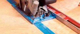
Feed the workpiece at an angle (1). This will not only protect against tears at the end of the board, but will also minimize the size of the step. Feed subsequent boards one after another, tightly joining their ends (2).
You can remove the step using one more technique: you need to slightly lift one end of the board at the entrance (photo 3), and do the same when accepting the workpiece at the exit (4).
Correct light warping without a jointer
Let’s not be misleading and say right away that a surface thicknesser is not able to cope with all types of warping. Correcting winging and other types of complex deformation is the competency of a jointer. But when it comes to simple longitudinal or transverse warping, the problem can be solved with a regular portable thicknesser.
When a curved board is fed into the machine, it is pressed with great force by the rollers and is temporarily leveled, but at the exit it takes its original shape. Thus, after passing through the thicknesser, the workpiece becomes thinner, but retains its curvature.
To prevent the rollers from straightening the board, you need to fill the gap between the warped board and the thicknesser table. For this it is convenient to use a thin lamella. In several passes through the thicknesser, the warped board acquires a perfectly flat top surface, in relation to which the back side is aligned without a lining.
Source