Purpose and classification of planing machines
Machines designed for processing workpieces by planing, chiselling and broaching constitute the seventh group of metal-cutting equipment according to the classification of Table.
1.5. The machines of this group, according to their design, are divided into longitudinal planing single- and double-column, cross-planing, slotting, horizontal broaching, semi-automatic machines for internal broaching and vertical-broaching semi-automatic machines for internal and external broaching. Longitudinal planing machines mod. 7210, 7212—7216 are two-post, and mod. 7110, 7112, 7116 - single-column. All single-column and double-column longitudinal planing machines have a caliper rotation angle of 60°. For machines mod. 7212G and 7216G, the maximum movement of the head sleeve is 200 mm, and the carriage feed is stepless 20...125 mm/min.
The domestic industry produces the following models of cross-planing machines: 7A311, 7E35, 7M36, 7D36, 7D36Ts, 7307, 7307D, 7D37Ts, 7310D. Machines mod. 7A311 and 7E35 - with mechanical drive, the rest - with hydraulic drive. For all machines except mod. 7A311, 7E35 and 7307, the slider speed is 3...48 m/min.
There are universal and specialized planing machines. Universal ones include transverse and longitudinal planing, as well as slotting. Cross-planing machines are used to process horizontal, vertical and inclined surfaces of parts.
Horizontal semi-automatic broaching machines for internal broaching are represented by models 7B55, 7B66U, 7B56, 7B56U, 7B56SAU, 7B57 and 7B58. Semi-automatic mod. 7B55U and 7B56U are modifications of semi-automatic machines, respectively mod. 7B55 and 7B56 and are distinguished by the absence of an attached frame with a mechanism for automatic supply and removal of the broach. Vertical broaching semi-automatic machines for internal and external broaching are characterized mainly by the following models: 7B64, 7B65, 7B66, 7B67, 7B68, 7B74, and models 7B64, 7B65, 7B66, 7B67 are intended for internal broaching, and the rest - for external broaching. Semi-automatic mod. 7V75D and 7V76D are double with two skids and two underwater tables operating alternately.
The machine tool industry produces slotting machines of the following models: 7A412, 7D430, 7D450, 7410, 7414. Machines mod. 7D430 and 7D450 with hydraulic drive, the rest with electric drive. At the same time, the machines mod. The 7410 and 7414 are driven by variable DC motors. All machines have a table rotation angle of 360°.
Description of the circuit diagram
The electrical circuit of the machine provides:
- Starting and stopping the main drive electric motor.
- Starting and stopping the electric pump.
- Starting and stopping the electric motor for rapid table movements.
- Remote control of the cutter from a push-button station (start and stop).
- The operation of the table movement counting mechanism.
- Limitation of idling speed of the main electric motor.
- Local lighting of the machine.
1. Starting the engine of the main drive 1M is carried out in the following sequence: by turning the packet switch BB1, a voltage of 380V is supplied from the three-phase alternating current network to the electric motors and control circuit. After pressing the 1KU (start) button, the current flows through the circuit L16-2-3-4-5-6-L26.
The current, having passed through the coil of the magnetic starter 1K, turns on the main contacts 1K at points L12-L13, L22-1S2, L32-Lzz and starts the electric motor of the main drive 1M. At the same time, the magnetic starter bypasses the 1KU button at points 3-4.
To turn off the main electric motor 1M, you must press the 2KU (stop) button, which opens its N.C. contacts at points 2-3 and de-energizes the coil circuit of the 1K magnetic starter.
2. Turning on and off the electric pump 2M is done by turning the packet switch BB2.
3. Starting and stopping the electric motor of accelerated movements “ZM” is carried out by the “ZKU” (start) button, operating in jog mode.
4. Remote control of the cutter from a push-button station can be carried out in two modes - setup and working.
- Work mode. The PC cycle switch at points 9-10 is open. To start the cutter, you need to press the 4KU button, which, with its NO contacts at points 7-8, will close the circuit of the electromagnet EM-2, which, through a gear drive, will turn the hydraulic panel control valve to the “start” position. The dolly will begin to move. To stop the cutter, you need to press the “2KU” button, which with its NO contacts will close the circuit of the electromagnet EM-1 at points L16-10. The latter, through a gear transmission, will turn the hydraulic panel valve to the “stop” position. The goon will stop.
- Setup mode. The PC cycle switch is closed at points 9-10. The cutter is controlled by only one button 4KU, which turns on EM-2 with its NO contacts, and with N. 3. contacts along the L16-7-9-10-L26 circuit turns on the EM1 electromagnet. The cutter can be started only after the main engine has started, when the N.O. contacts L16-7.
5. The final microswitch of the table movement counting mechanism “1KB” is built into the control circuit of the main electric motor “1M”. When receiving a command from the reference mechanism, the limit switch “1KB” opens the circuit L16 2-3-4-5-6-L26 at points L16-2 and de-energizes the coil circuit of the magnetic starter 1K.
6. The idling speed of the main electric motor is limited by the “2KU” button, which has (N. 3.) contacts in the main engine control circuit at points 2-3 and N.O. contacts in the cutter stop circuit at points L16-10. Thus, when the cutter stops, the main engine will also stop.
7. The local lighting lamp is powered by a reduced voltage of 36 V AC from the secondary winding of a 380/36/6 V transformer. In the light bulb circuit “L1” there is a fuse “ZPR” and a switch “VO”. The signal light L is connected to pin 6v through the damping resistance PS.
The signal light L2 lights up when voltage is applied from the network by turning the package switch BB1.
Cross planing machines
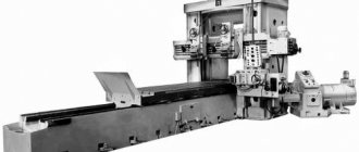
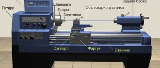
Let's consider the technical characteristics and design features of the cross-planing machine mod. 7E35, designed for processing flat and shaped surfaces on small workpieces in single or small-scale production conditions, for example in tool and repair shops.
Technical characteristics of the machine mod. 7E35
Maximum stroke length of the slider, mm……………………..520
Number of double strokes of the slider in 1 minute………………………… 13.2; 19; 26.5; 37.5; 53; 75; 106; 150
Horizontal table feeds in one double stroke
slider, mm………..0.2; 0.4; 0.6; 0.8; 1.0; 1.2; 1.4; 1.6; 1.8; 2.0; 2.2; 2.4; 2.6; 2.8; 3.0; 3.2; 3.4; 3.6; 3.8; 4.0
Vertical feeds of the caliper in one double stroke
slider, mm………………………………………………………. 0.16; 0.33; 0.50; 0.66; 0.83; 1.0
Engine power, kW……………………………………. 5.5
Machine efficiency……………………………………………………………… 0.65
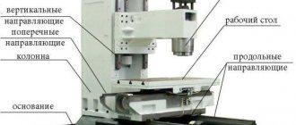
The main parts of the cross-planing machine mod. 7E35 (Fig. 1) are:
- bed 6 - a massive cast iron casting with ribs and partitions inside for strength and rigidity; The machine drive, gearbox and rocker mechanism are placed inside;
- slider 5 is a cast iron hollow casting that moves along the upper horizontal guides of the frame; to ensure strength, stiffening ribs are located inside; the quality of processing depends on the smoothness and accuracy of movement along the guides;
- a support 4 with a tool holder 3, in which the cutter is mounted, is located in the front part of the slide;
- table 2 is fixed to the front wall of the frame and supported by a bracket.
Rice. 1. Design of a cross-planing machine model 7E35 : 1 - bracket; 2 - table; 3 — tool holder; 4 — caliper; 5 - slider; 6 - bed; 7, 8 - horizontal and vertical feed mechanisms, respectively
The movement of the cutter in the direction of the workpiece, during which chips are removed, is called the working stroke, and the movement in the opposite direction (no work is performed) is called the idle stroke.
Technical characteristics of cross-planing machines of the industrial group "ASV" are given in table. 1.
Table 1. Cross-planing machines
| Model | Slider stroke, mm | Table dimensions, mm | Dimensions (L W H), mm | Weight, kg |
| 7305T | 510 | 400 500 | 2310x1055x1550 | 1980 |
| 7307GT | 710 | 450 600 | 2790x1235x1665 | 2770 |
Equipment operation
When operating machines, a number of rules must be observed:
- Before carrying out work, you need to make sure that the cutter and the workpiece are securely fastened;
- to prevent overheating of the working tool, a stable supply of lubricating or cooling liquids is required;
- moving parts must be in protective covers;
- It is not allowed to process parts whose dimensions or weight exceed the technical requirements of the machine manufacturer;
- It is prohibited to start work until a stable speed has been reached;
- periodic inspections and maintenance are required;
- maintenance of mechanisms clean is required;
- To avoid short circuits in the supply circuits, it is necessary to ensure an optimal level of humidity in the room.
Some devices are equipped with fasteners for simultaneous fixation of several incisors. This allows processing of complex surfaces with high productivity, since time is not wasted on rearranging cutting tools. There are one-, two- or four-sided fastenings.
We turn a planer into a slotting machine!
Longitudinal planing and slotting machines
Universal two-column longitudinal planing machine mod. 7212 is designed for finishing surfaces and cutting long grooves of various profiles.
Technical specifications. The largest transverse dimensions: width - 1250 mm; height - 1120 mm; dimensions of the working surface of the table - 1120... 4000 mm; caliper feed: when moving along the crossbar - 0.5...25; for other movements - 0.25...12.5 mm/d. move. The main unit of the machine is the table on which the workpiece is fixed. The table moves back and forth relative to the fixed cutters installed in the supports. The table movement is the main cutting movement; the reverse motion of the table is auxiliary, carried out at high speed, and during the reverse motion the cutters rise. The supporting system of the machine consists of a bed, a stand and a connecting beam at the top.
Two calipers on the crossbar and one caliper on the stand make vertical and horizontal movements and are used for installation or are used for periodic feeding of cutters, as well as their deepening. The caliper can be rotated at an angle of 60°. A table drive is mounted next to the frame.
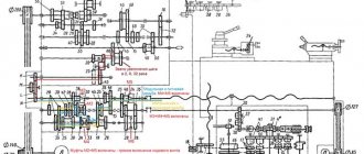
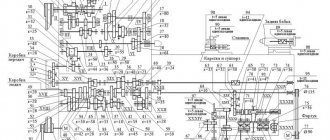
The main movement is the cutting movement, i.e. the movement of the table with the workpiece being processed is communicated from the M1 DC motor through a two-stage gearbox with an M1 gear coupling and a helical rack and pinion gear (Fig. 2). Maximum table movement speed vmax = (17/63) (26/49) 3.14 12 10 = 80 m/min. Technical characteristics of slotting machines are given in table. 2.
Table 2. Slotting machines
| Model | Stroke of the cutter, mm | Table movement, mm | Rotary table diameter, mm | Dimensions (L W H), mm | Weight, kg |
| GD 200 | 120…200 | 500 400 | 500 | 1900x1270x2175 | 2100 |
| GD 320 | 120…320 | 650 510 | 770 | 2850x2160x3010 | 5660 |
| GD 500 | 120…500 | 800 650 | 940 | 3440x2760x3465 | 8160 |
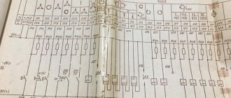
Rice. 2. Kinematic diagram of a two-column longitudinal planing machine : a - crossbar clamping mechanism; b - table; c — control panel
Options, descriptions
Principle of operation:
- Tabletops, chair seats, etc. – to mill such workpieces, a template of the required shape is attached to the center of the table, the workpiece is placed on the template and pressed from above with a central pneumatic clamp. The table with the workpiece rotates - the workpiece is processed around the entire perimeter in one pass by one milling unit. You can install several workpieces on top of each other at the same time.
- Chair legs, chair backs, etc. – for longitudinal milling of such workpieces, templates are attached around the perimeter of the table, the workpieces are placed on the templates and fixed with special pneumatic clamps also located along the perimeter of the table. The table rotates; several workpieces are processed per revolution (depending on their size). During this operation, the table does not stop; the operator has time to remove the processed product and install a new workpiece in its place, because workpieces are pressed automatically - this allows you to achieve high productivity.
Processing scheme:
Examples of processed parts:
Device
The jointing machine consists of the following elements:
- Engine. It operates from a mains voltage of 220 V. The electric motor creates and transmits torque to the planing shaft with knives.
- Desktop. This element consists of rear and front plates. They are made of cast iron and equipped with stiffening ribs that ensure stability of the working surface. The edges of the plates are equipped with stainless steel overlays. They protect the desktop from destruction. The back plate is flush with the top of the cutting blades. The front plate is located under the back plate, at a distance of up to 2 mm. The distance between the levels depends on how much material needs to be removed when processing a wooden product.
- Bed. It is made from durable metal alloys. This part can withstand the weight of the machine and all the forces that arise when the cutting elements act on the surface of the workpiece. The frame contains shafts with knives, guides and fastenings.
- Planing shaft. It is located between the back and front plates. Blades of equal thickness are attached to the shaft. They are made of tool high-speed steel. To process bars made of dense wood, it is recommended to equip the shaft with carbide-tipped cutters.
- Guide. It is a unit designed to move the moving elements of the machine and the workpiece being processed. The guide is attached to the frame using bolts. It can move in the transverse direction.
- Circular fencing. It is located on the front plate and fits tightly to the guide. The circular guard is made of sheet materials and protects the knife shaft.
Using a jointer it is recommended to process parts with a length of 1 to 1.5. Longer workpieces are poorly secured to the work table and are deformed, which reduces the cutting accuracy and creates inconvenience during the work process. Processing workpieces less than 1 m long is dangerous.