The predecessors of the 16k20 lathe, produced by Soviet machine builders, were a number of screw-cutting lathes equipped with a gear gearbox. These metal-cutting machines bore names from DIP-200 to DIP-500. The abbreviation of the names spoke of the desire of the leadership, supporting the slogan of the 1st Five-Year Plan to catch up and overtake the leaders of capitalism.
The number following the letter part of the name corresponded to the height of the centers of the machine relative to the bed in mm. Machines with such names were produced from 32 to 37 of the last century. The change of names occurred as a result of the development and approval of the “Unified System of Symbols for Machine Tools” (USUS). According to the adopted document, the founder of the generation changed the name of DIP-200 to 1D62. However, the outdated name is still used as a general name for lathes with center heights of about 200 mm.
Brief history of the series
Two years later, in 1934, production of such models as DIP-300, DIP-400, DIP-500 was launched.
By 1937, special types of nomenclature and sizes were being developed. A unified system of symbols is adopted. Thus, the first machine produced by the plant was named 1D62, but the abbreviation DIP-20 was retained.
The year 1940 was marked by the creation of the 162K 26A machine, as one of the versions of the DIP-200.
Then various modernized machines were produced, and in 1948, the legendary 1A62 appeared. The models were produced in large quantities.
And finally, in 1971, the first prototype of the 16 to 20 machine was manufactured. The machine even received a gold medal at the fair in ’72.
From 1972 to 1973, reconstruction was carried out at the plant, this is due to the large-scale production of new 16K20 models. The company is developing mass production of this model, and at the end of 1973, the monthly production turnover reaches 1 thousand copies. About 10% of the total is exported.
Then various modifications of the 16 to 20 model appeared, including 16 K 25, 16 K2 0M, 16 K2 0P, 16 K 20V, 16 K 20G, 16 K 20K, 16K20F1, 16K20PF1, 16K20VF1 and others. All were based on the basic standards of the 16 to 20 model.
1988 will mark the end of production of machines of this model. It was replaced by the MK series.
Operator's manual for screw-cutting lathe 16K20RF3S32 with CNC 2P22
This manual contains information for the operator on servicing the 16K20RF3S32 machine with a 2P22 or 2P22.01 CNC system. Contents of the operator's manual:
- Purpose of the program
- Program execution conditions
- Program Execution
- Operating procedure
- General provisions
- Linking the device to machine parameters
- Linking the reference system to the machine
- Linking a tool to a reference system
- Linking a reference system to a part
- Semi-automatic input of the initial position and exit of the tool to this position
- Input mode
- Program output
- “Manual control” mode
- Automatic mode
- Test mode
- Coding system and frame order
- Programming chamfers, arcs and fillets
- Programming canned cycles
- Drawing up programs when entering from punched tape
- Messages to the operator
- Device exchange signals
- Algorithms for the operation of electrical automation of a controlled machine
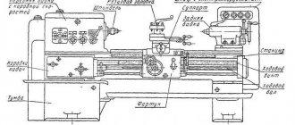
Machine design
The basis of the device is a durable U-shaped frame with 2 hardened, ground guides on top. It is installed on pedestals in a cast metal support, which is used as a trough for emulsion and collecting chips. The main electric drive is located in the cabinet on the headstock side of the product.
Dimensions of screw-cutting lathe 16K20
Machine dimensions: length 2505, 2795, 3195 or 3795 mm; width 1190 mm; height 1500 mm. The weight of the machine depends on its length and can be 2.835; 3.005; 3.225 or 3.685 per 103 kg.
Spindle
The spindle shaft is steel with a through longitudinal hole through which a rod is passed, used as a workpiece, or a drift when knocking out the front center. To rotate the spindle in this machine, specialized precision rolling bearings are used. They are distinguished by high manufacturing precision and wear resistance, so they do not require periodic adjustments during maintenance during the operational period.
The shaft supports are lubricated by oil supplied to them under pump pressure. The front end of the spindle shaft is made in accordance with GOST 12593 - with a short centering cone 1:4.
Headstock
The headstock or headstock of the workpiece serves to fix one end of the workpiece and transmit torque to it. It houses the spindle, bulkhead box and other components. On the outside there are switching levers for the bulkhead box.
The output shaft of the headstock of the product is connected through gears to the feed reducer. The latter allows the slide to carry out the feed movement using the drive shaft during turning. Or by means of a lead screw for thread cutting. Which can be connected to the feed box without intermediate links.
Apron
This unit is necessary to move the caliper with the tool holder both along and across the axis of rotation of the part. It converts the rotary motion of the screw into linear displacement of the caliper. You can move the latter not only manually, but also by taking away part of the rotational torque from the spindle. The apron of this machine is equipped with a high-precision feed cut-off device on a stop, a design that has not been seen before.
Caliper
Designed to hold the tool holder with the cutter fixed in it near the workpiece. Possessing several degrees of freedom, it can move under the influence of the apron to form the desired surface character of the part with a cutter. To control the amount of movement, the unit is equipped with scale rulers with sighting devices that increase the accuracy and ease of reading readings.
Tailstock
She's a stubborn grandma. It is installed on guides that allow it to move along the machine. It has a tapered hole coaxial with the headstock output shaft. Which allows you to set a center to support the second end of the blank. Or a reamer, tap, drill and other similar ones for performing operations from the open end of the workpiece.
Feed motion and thread cutting
The feed drive includes the following chains and components (see kinematic diagram):
- Thread pitch increasing link - provides an increase in the output rotation speed relative to the spindle speed in the ratio: 1:2, 1:8, 1:32. Provides a double block in the spindle head when connecting z = 45/45;
- Reverse mechanism - serves to change the direction of movement of the caliper with the same direction of spindle rotation. It is carried out by connecting the intermediate gear - snaffle;
- Guitar of replacement wheels - includes replacement gears K, L, M, N. Serves for relatively rare reconfiguration of speeds;
- Feed Box - The feed box receives movement from the headstock through the guitar and sets different rotation speeds for the lead shaft and lead screw;
- Feed mechanism - converts the rotation of the drive shaft into translational movement of the caliper, longitudinal, transverse or cutting slide. The lead screw must be turned off.
- The feed mechanism when cutting threads with a cutter converts the rotation of the lead screw into forward longitudinal movement of the caliper.
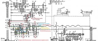
Kinematic diagram of the support and apron of the machine 16K20
Block diagram of feeds and thread cutting of a screw-cutting lathe 16k20
The feed movement is borrowed from the spindle in the spindle head when the z = 60/60 pair is running.
If it is necessary to increase the pitch, the movement is borrowed from shaft III with gear z = 45/45 engaged. In this case, the feed and thread pitch increase depending on the position of the blocks in 2; 8 and 32 times.
The reverse mechanism ensures right rotation of the lead screw through a pair of z = 30/45, left rotation through a gear z = 30/25 25/45.
When the machine leaves the factory, gears with a number of teeth z = 40/86, z = 86/64 in the replacement wheels K/L, M/N . This combination provides feeds and cutting of metric and inch threads in steps, the values of which are indicated in the table attached to the machine.
Kinematic chain of longitudinal and transverse feeds of the caliper
The kinematic feed chain coordinates the rotation of the spindle with the movement of the caliper in the longitudinal or transverse directions: for 1 revolution of the spindle, the caliper must move by an amount S.
Kinematic chain of longitudinal feeds of the caliper
The kinematic balance equation for the longitudinal feed chain has the form:
S = 1 rev. sp. · z1/z2 · π · m · z mm/rev ,
Where:
- z1/z2 — gear ratio of the feed drive from the spindle to the rack wheel;
- π·m·z is the length of the pitch circle of the rack and pinion wheel. π m z = 3.1416 3 10 = 94.248;
- m - rack module, m = 3 mm;
- z is the number of teeth of the rack and pinion wheel, z = 10.
The universal feed box 16B20P.070 provides longitudinal feeds (22 pcs), mm/rev:
- 0,05; 0,06; 0,075; 0,09; 0,1; 0,125; 0,15; 0,175; 0,2; 0,25; 0,3; 0,35; 0,4; 0,5; 0,6; 0,7; 0,8; 1; 1,6; 2; 2,4; 2,8; 2,4; 2,8
The equation of the kinematic chain to obtain the minimum longitudinal feed can be written in the following form:
Kinematic chain of transverse caliper feeds
The equation for the kinematic balance of the cross feed chain has the form:
S = 1 rev. sp. · z1/z2 · р mm/rev ,
Where:
- z1/z2 — gear ratio of the feed drive from the spindle to the rack wheel;
- p — pitch of the cross-feed screw, p = 5 mm
The complete kinematic balance equation for the minimum cross feed chain is:
Accordingly, the kinematic chain of the transverse feed coordinates the rotation of the spindle and the transverse lead screw; the amount of transverse feed with the same machine setup is 1/2 of the longitudinal feed.
The kinematic chain equation for obtaining the maximum lateral feed can be written as follows:
In the feed box of a 16k20 screw-cutting lathe, the feeds are not located in a geometric row, so the machine is set to the required feed according to the tables located on the headstock panel.
In the case of cutting precise threads, rotation can be transmitted from the replacement wheels directly to the lead screw with a pitch of t = 12 mm through shafts XII, XVII, XXIII with gear couplings M2 and M5 engaged, bypassing the feedbox mechanism.
and transverse feeds (24 pcs), mm/rev:
- 0,025; 0,03; 0,0375; 0,045; 0,05; 0,0625; 0,075; 0,0875; 0,1; 0,125; 0,15; 0,175; 0,2; 0,25; 0,3; 0,35; 0,4; 0,5; 0,6; 0,7; 0,8; 1; 1,2; 1,4
Kinematic chain for cutting metric threads
When cutting a thread, in one revolution of the spindle, the support (cutter) must move by the thread pitch Рр.
The kinematic balance equation for the metric thread cutting chain has the form:
S = Рм = 1 rev. sp. · z1/z2 · Рх mm/rev ,
Where:
- z1/z2 —gear ratio of the feed drive from the spindle to the lead screw;
- Px is the pitch of the machine lead screw in mm (Px = 12 mm).
Kinematic balance equation for cutting metric threads with a minimum pitch:
Kinematic chain for cutting inch threads
When cutting inch threads, the pitch is specified by the number of threads per inch, all thread parameters are expressed in inches (inch = 25.4 mm).
For inch pipe threads, the size in inches conventionally characterizes the clearance in the pipe, and the outer diameter is, in fact, significantly larger.
Inch thread pitch in millimeters:
Pd = 25.4/k mm/rev,
Where:
- k - number of threads per inch of thread (1″ = 25.4 mm);
Kinematic balance equation for cutting inch threads with a minimum pitch:
Kinematic chain when cutting modular threads
Modular threads are usually used when cutting worms.
The pitch of a modular thread is expressed through the module - a number that is a multiple of pi (3.14).
Modular thread pitch in millimeters:
Pm = 3.14 m mm,
Where:
- m is the thread pitch in modules;
Download the passport of the machine 16A20F3 with CNC NC-202 for free.
A 16A20F3 screw-cutting lathe with an NC-202 CNC device is equipped with an Inverter Hyundai N300 main drive and two HA-075 feed drives along the Z and X axes. An additional feature of this machine is that it is equipped with an Inverter Delta VFD-M drive that performs the function of clamping and releasing the quill and chuck and control of the toolholder head. It is designed for automatic turning of external and internal surfaces of parts such as bodies of revolution with stepped and curved profiles of varying complexity according to a pre-compiled control program. Deviation from cylindricity is 7 microns, taper is 20 microns at a length of 300 mm, deviation from straightness of the end surface at a diameter of 300 mm is 16 microns. Area of application of the machine: small-scale and mass production.
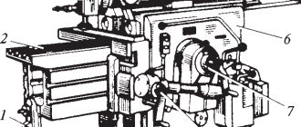
Milling machine 6T12F20-1 The cantilever-vertical milling machine with operational program control (OPC) model 6T12F20 is designed for performing a variety of milling work with cylindrical, angular, shaped, face and other cutters. A wide range of spindle speeds and table feeds allows for efficient processing of parts made of cast iron, steel, difficult-to-machine alloys, non-ferrous metals, light alloys and plastics. The machines can process parts of complex configurations that have vertical and horizontal planes, frames, grooves, ledges, etc.
Versatility
The technical characteristics of the 16K20F3 screw-cutting lathe allow it to be used for the following operations:
- Drilling holes of various diameters.
- Processing of workpieces from the end parts.
- Countersinking.
- Thread cutting.
- Boring and finishing of conical and shaped surfaces.
The screw-cutting pairs are protected by special limiters that help prevent premature failure of the mechanisms. The modernization of the units under consideration consists of equipping them with CNC kits of domestic and foreign production with replaceable electrical systems. Re-equipment makes it possible to increase power by 2-3 times, depending on the condition of the units. All these solutions increase equipment productivity and reduce the transformation of workpieces. It is advisable to carry out modernization simultaneously with major repairs.
Technical capabilities and characteristics of 16K20
Screw-cutting lathes 16K20 (as well as their analogues) are distinguished by the following characteristics.
- The spindle can rotate in the frequency range of 12.5–1600 rpm.
- It is allowed to process parts whose maximum cross-section is 310 mm above the recess, 400 mm above the bed and 220 mm above the support.
- Rapid movements in the transverse direction can be made at a speed of 1.9 m/min, longitudinal movements - 3.8 m/min.
- The technical capabilities of the 16K20 screw-cutting lathe allow it to produce threads with various parameters. Their pitch can be in the range: 0.5–56 (modular and pitch), 0.5–112 threads per inch (inch), 0.5–112 mm for metric.
- The length of the workpiece can be up to 2000 mm.
- The number of longitudinal and transverse feeds is 22 and 24, respectively. The range of longitudinal feeds is 0.05–2.8 mm/rev, transverse feeds are 0.025–1.4 mm/rev.
- The characteristics of the 16K20 machine allow processing workpieces weighing up to 1300 kg.
- To rotate the spindle, you can select one of 22 speeds (direct).
- The hole in the spindle has a diameter of 52 mm.
The kinematic diagram of the machine can be found in the photo below:
Kinematic diagram of the 16K20 machine (click to enlarge)
Depending on the length indicated in the equipment passport, the weight of the 16K20 machine can be:
- 3685 kg (for model with a length of 3795 mm);
- 3225 kg (3195 mm);
- 3005 kg (2795 mm);
- 2835 kg (2505 mm).
The engine power of the hydraulic station and the main drive of the 16K20 machine (according to the passport and actual) is 11 kW. Accordingly, this indicator is taken as the power of this model.
Controls of the machine 16K20
To start the 16K20 screw-cutting lathe, the operator needs to press a button, which closes the electrical circuit in the contactor coil. In addition to the main button, the machine has a number of elements through which the following equipment options are controlled:
- moving the equipment support and carriage at high speeds (this option is controlled using the so-called jog button);
- stopping the rotation of the equipment motor;
- starting and stopping the coolant pump.
The electrical circuit of the 16K20 screw-cutting lathe also contains a special relay, which serves to limit the idle speed of the engine. The diagram itself can be found below:
Circuit diagram of a 16K20 lathe (click to enlarge)
The handles located on the machine body are used to solve such problems as:
- selection of the type of work to be performed: type of thread to be cut and feed characteristics;
- quill fixation;
- friction clutch control;
- movement of the carriage and longitudinal movement of the slide;
- setting the thread pitch and feed value for its execution;
- disabling the feed box - for those cases when the thread is cut directly;
- selection of spindle rotation mode – number of revolutions;
- turning the lead screw nut on and off;
- start button of the input circuit breaker;
- choice of thread cutting direction;
- selecting a mode for cutting threads with normal or increased pitch.
On 16K20 machines, a steady rest can be used, which is designed to prevent the workpiece from bending during work, and also helps to fix it, thereby increasing the accuracy of processing. The lunette looks like this:
Steady rest for screw-cutting lathe 16K20
Design and principle of operation
The 16K20FZ turning machine is used for work carried out when processing the internal and external surfaces of products according to a pre-established program. Mostly, products with internal surface dimensions not exceeding 100 cm and external surface dimensions not exceeding 40 cm are finished.
The design and kinematic diagram of the 16K20FZ lathe is made according to a traditional layout that complies with universal standards and has characteristics that allow it to perform a wide range of operations. The equipment consists of units and mechanisms:
- grounds;
- beds;
- caliper carriages;
- rotary tool holder;
- tailstock;
- guides;
- automatic transmission;
- headstock;
- electromagnetic couplings;
- drives (transverse and longitudinal);
- hydraulic booster.
The metal workpiece is fixed in a spindle, which is driven into rotation by an electric motor that provides operation through a V-belt drive, the speed of which is regulated by an automatic transmission and a spindle head gearbox. The automatic transmission has 6 electromagnetic clutches, which, using their combined activation, select the required 1 of 9 possible shaft rotation speeds.
Kinematic diagram 16K20F3
To change the rotation speed, spindle head gears are used, which have manual switching and are capable of adjusting rotation in 12 modes.
The machine carriage has the ability to make longitudinal displacements using an electromagnetic drive. The transverse transmission of the caliper with the tool holder is carried out using a drive, a gear wheel, and a lead screw.
Turret head 16K20F3
The rotary tool holder can be installed in six positions, changing angles with a horizontal axis of rotation of the plane and mounted on a transverse support. The tool holder positions the tool head, in which up to six cutters used for finishing the workpiece can be mounted according to a given program.
The hydraulic drive, which includes a hydraulic station and two hydraulic boosters, is equipped with:
- control pump;
- drive;
- container with oil;
- control equipment.
Hydraulic drive mechanisms provide all the basic processes associated with the operation of the units.
Kinematic diagram of a screw-cutting lathe 16K20
Technical specifications, drawings and descriptions of components are given on page 16K20 .
16K20 screw-cutting lathe replaced the legendary but outdated 1K62 machine in 1972. The 16k20 machine is superior to the 1K62 model in all quality indicators (productivity, accuracy, durability, reliability, etc.).
In 1988, the 16k20 was replaced by the more modern MK6056, MK6057, MK6758.
The kinematic diagram of the 16k20 is given to understand the connections and interaction of the main elements of the machine. The numbers of teeth (z) of the gears are indicated on the callouts (the asterisk indicates the number of worm runs).
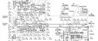
Kinematic diagram of a screw-cutting lathe 16K20
Kinematic diagram of the spindle head of a 16K20 screw-cutting lathe
Block diagram of the gearbox of a screw-cutting lathe 16K20
Block diagram of the gearbox of a screw-cutting lathe 16K20
The main movement drive consists of a single-speed three-phase asynchronous electric motor and a stepped mechanical gearbox. From the electric motor Ml with ndv = 1460 rpm (Fig. 4.3), through a V-belt drive with pulley diameters Ø 140 and Ø 268 mm, shaft I of the gearbox rotates, on which freely rotating gears with a number of teeth z = 56 and z = 51 are installed. for forward spindle rotation (clockwise) and z = 50 for reverse spindle rotation (counterclockwise).
Direct or reverse rotation of the spindle is activated using a double friction clutch Mf1.
Shaft III receives two rotation speeds through wheels z = 34 or z = 39.
Next, using gears z = 29, z = 21 or z = 38 and engaging with one of the corresponding rims z = 47, z = 55 or z = 38 and forming a triple block, shaft IV is driven into rotation.
From shaft IV, rotation can be transmitted directly to the spindle: through gears z = 60 or z = 30 to a block with z = 48, z = 60 or through shafts V and VI, which together with the gears form a pick-up group. In this case, rotation is transmitted by gears z = 45 or z = 15 (on shaft IV), engaging with one of the block rims z = 45, z = 60 (on shaft V), and pairs of wheels 18/72 and 30/60.
In addition to the gearbox, a buster . By brute force we mean an additional gear train, with the help of which an increase in the number of spindle speeds is achieved. In addition, the presence of overdrive makes it possible to obtain low speeds and, accordingly, high torque values on the output shaft of the box.
The minimum and maximum frequencies of direct rotation of the spindle are determined:
Where:
η is the slip coefficient of the belt drive, in calculations we take η = 0.985
ndv - rotation speed of the electric motor ndv = 1460 rpm
140/268 - the ratio of the diameter of the transmitting pulley to the diameter of the receiving pulley. Drive pulley diameter Ø 140, Driven pulley diameter Ø 268 mm
It should be noted that when calculating the spindle rotation speed using the equations of the kinematic chains of the gearbox, the result may not coincide with the spindle rotation speeds indicated in the technical characteristics of the machine, calculated theoretically according to the laws of the geometric series (GOST 8032-84).
Kinematic chains of forward and reverse rotation of the spindle
Spindle speed chart for screw-cutting lathe 16k20
Depending on the options for including gears in the gearbox, you can get 22 different spindle speeds.
CNC system
The 16K20F3 lathe is equipped with various CNC systems. Machine modifications, depending on the configuration of the CNC device, have different indices (for example, 16K20F3S32). The contour CNC system ensures the movement of shaping, changing the feed rates and spindle speeds in the processing cycle, indexing the rotary tool holder, and cutting threads according to the program. The number of simultaneously controlled coordinates is 2, the total controlled coordinates are 2. The discreteness of specifying transverse feed movements (along the X axis) is 0.005 mm, longitudinal movements (along the Z axis) is 0.01 mm. The 16K20F3 machine with a 2P22 CNC device is equipped with a KEMRON main drive and a KEMTOK feed drive along the Z and X axis.
Designation
The alphanumeric index of the machine 16K20F3 means the following: number 1 is a lathe; number 6 - designates a screw-cutting lathe, letter K - generation of the machine, number 20 - height of the centers (200 mm). The presence of “F3” at the end of the index indicates the presence of CNC - numerical program control.
| Specifications | Options |
| Machining diameter above the bed, mm | 500 |
| Machining diameter above the support, mm | 200 |
| Maximum processing length, 6-position head, mm | 900 |
| Maximum processing length, 8-position head, mm | 750 |
| Maximum processing length, 12-position head, mm | 850 |
| Maximum processing length in centers, mm | 1000 |
| Diameter of cylindrical hole in spindle, mm | 55 |
| Maximum lateral stroke of the caliper, mm | 210 |
| Maximum longitudinal stroke of the caliper, mm | 905 |
| Maximum recommended speed of longitudinal working feed, mm | 2000 |
| Maximum recommended speed of transverse working feed, mm | 1000 |
| Number of controlled coordinates, pcs. | 2 |
| Number of simultaneously controlled coordinates, pcs. | 2 |
| Discreteness of movement task, mm | 0,001 |
| Spindle speed limits, min-1 | 20 — 2500 |
| Speed of fast movements of the caliper - transverse, mm/min | 2 400 |
| Maximum speed of fast longitudinal movements, mm/min | 15000 |
| Maximum speed of fast transverse movements, mm/min | 7500 |
| Number of tool head positions | 8 |
| Power of the electric motor of the main movement, kW | 11 |
| Accuracy class according to GOST 8-82 | P |
| Overall dimensions of the machine (L x W x H), mm | 3700 × 2260 × 1650 |
| Machine weight, kg | 4000 |
Design Features
The high-strength machine bed 16K20F3 is made of cast iron SCh20 with heat-treated ground guides, ensuring long service life and increased processing accuracy. The main movement drive, which includes a 11 kW main motor and a spindle head, provides the highest torque of up to 800 Nm. High-precision spindle with a 55 mm bore (64 mm on request), allowing the processing of parts made of bar material. The processing area can be equipped with either a linear adjustment or a turret, depending on the customer's requirements. Reliable protection of ball screw pairs ensures the durability of the movement mechanisms along the X and Z coordinates. The 16K20F3 machine is equipped with CNC systems and electric drives, both domestically produced and manufactured by foreign companies. Feedback and threading sensors model VTM-1M.
Control
The tool movement program, main drive control and auxiliary commands are entered into the control system memory from the operator console keyboard, as well as from an external memory cassette and can be adjusted from the CNC operator console with visualization on the digital display panel.
Automatic tool head
The 16K20F3 CNC lathe is equipped with a 6-, 8- or 12-position automatic universal head (UG9321, UG9324, UG9325) with a horizontal rotation axis. The head has a tool disk for 6 radial and 3 axial tools (6-position) or 8 blocks for radial and axial tools (8-position) or 12 blocks for radial and axial tools, combined when setting up a part (12-position).
Design of the spindle (front) headstock with gearbox
Gearbox of screw-cutting lathe 16k20
Spindle head of screw-cutting lathe 16k20
All gearbox shafts and the spindle rotate on rolling bearings, which are lubricated both by splashing (the gearbox is filled with oil) and by force, using a pump. The feed movement from the spindle is transmitted to the bit shaft and then to the feed mechanism.
Spindle revolutions per minute - forward rotation (22 pcs): 12.5-16-20-25-31.5-40-50-63-80-100-125-160-200-250-315-400-500 -630-800-1000-1250-1600.
Spindle revolutions per minute - reverse rotation (11 pcs): 19-30-48-75-120-190-300-476-753-1200-1900.
The spindle and all shafts are mounted on rolling bearings. The front spindle support contains a radial double-row roller bearing, in which preload is created by fitting the inner ring onto the tapered journal of the spindle. If you push the ring onto the cone with a nut, it expands and puts pressure on the rollers.
The rear spindle support has two angular contact ball bearings that absorb radial and axial loads; The preload is adjusted with a nut tightening the inner rings.
Shafts II…V of the gearbox are mounted on tapered roller bearings, which is convenient for assembly and disassembly; the preload is adjusted using pressure screws 3. Since shafts III and IV are long, a middle support is provided for them.
On the left side of the friction clutch 13, which reverses the movement of the spindle, there is a large number of disks, since large torques are required in the forward direction of rotation. A special feature of gear blocks is the adhesive connections between the rims and the hubs.
The wheel hub Z= 60 on shaft III is a band brake disc; The rod of the control mechanism, setting the clutch in the neutral position, turns on the brake (by pressing roller 1).
Prevention and repair
Daily care activities
Before starting work:
- Inspection of the machine.
- Lubricate the lead screw and shaft.
- Controlling the amount of oil.
- Switching on with checking nodes without load.
During operation:
- Switch feeds and gears only after the moving units have finally stopped.
- When working with cast iron or abrasive materials, cover the guides with thick cloth.
After the end of working hours: turn off the power supply, remove the shavings, wipe with a rag soaked in kerosene, and lubricate the open guides with oil.
Malfunctions and their elimination
| Symptoms | Cause | Correction method |
| Ovality of the part or hole being bored. | Blank runout in the cartridge. | Boring of jaws. |
| Quill play or weak fastening of the thrust headstock. | Adjusting or repairing the quill. | |
| Hole axis offset. | Misalignment of spindle shaft and tailstock. | Adjustment. Or repair with adjustment. |
| Significant cone of cylindrical parts. | Mismatch between the centers of the spindle shaft and the thrust head. | Adjustment. |
| Worn caliper or bed guides | Adjustment or repair. | |
| Dimensional instability during trimming. | Axial play of the spindle shaft. | Replacing rotation bearings. |
A slight increase in caliper clearances can be eliminated by adjusting the wedges in the transverse or upper slide guides, and the adjustment screws in the rear guide of the longitudinal slide. Then, moving the slide to the maximum distance, make sure that it moves smoothly. Leaks in the screw drive of the cross slide are eliminated by adjusting the screws located behind the tool holder platform.
Technical characteristics of the lathe 16K20
| Parameter name | 16K20 | 16K20P |
| Basic machine parameters | ||
| Accuracy class according to GOST 8-82 | N | P |
| The largest diameter of the workpiece installed above the bed, mm | 400 | 400 |
| Height of the center axis above the flat guides of the frame, mm | 215 | 215 |
| The largest diameter of the workpiece processed above the support, mm | 220 | 220 |
| Maximum length of the workpiece installed in the centers (RMC), mm | 710, 1000, 1400, 2000 | 710, 1000 |
| The greatest distance from the axis of the centers to the edge of the tool holder, mm | 225 | 225 |
| The largest diameter of the drill when drilling steel parts, mm | 25 | 25 |
| Maximum mass of workpiece processed in centers, kg | 460..1300 | 460..1300 |
| Maximum mass of workpiece processed in the chuck, kg | 200 | 200 |
| Spindle | ||
| Spindle hole diameter, mm | 52 | 52 |
| The largest diameter of the rod passing through the hole in the spindle, mm | 50 | 50 |
| Spindle rotation speed in forward direction, rpm | 12,5..1600 | 12,5..1600 |
| Spindle rotation speed in reverse direction, rpm | 19..1900 | 19..1900 |
| Number of forward spindle speeds | 22 | 22 |
| Number of spindle reverse speeds | 11 | 11 |
| Spindle end according to GOST 12593-72 | 6K | 6K |
| Tapered spindle bore according to GOST 2847-67 | Morse 6 | Morse 6 |
| Spindle flange diameter, mm | 170 | 170 |
| Maximum torque on the spindle, Nm | 1000 | 1000 |
| Caliper. Submissions | ||
| Maximum length of longitudinal movement, mm | 645, 935, 1335, 1935 | 645, 935 |
| Maximum length of transverse movement, mm | 300 | 300 |
| Speed of fast longitudinal movements, mm/min | 3800 | 3800 |
| Speed of fast transverse movements, mm/min | 1900 | 1900 |
| Maximum permissible speed of movement when working on stops, mm/min | 250 | 250 |
| Minimum permissible speed of movement of the carriage (support), mm/min | 10 | 10 |
| Price for dividing the longitudinal movement dial, mm | 1 | 1 |
| Transverse movement dial division price, mm | 0,05 | 0,05 |
| Longitudinal feed range, mm/rev | 0,05..2,8 | 0,05..2,8 |
| Transverse feed range, mm/rev | 0,025..1,4 | 0,025..1,4 |
| Number of longitudinal feeds | 42 | 42 |
| Number of cross feeds | 42 | 42 |
| Number of threads to be cut - metric | ||
| Number of threads to be cut - modular | ||
| Number of threads cut - inch | ||
| Number of threads to be cut - pitch | ||
| Limits of metric thread pitches, mm | 0,5..112 | 0,5..112 |
| Limits of pitches of inch threads, threads/inch | 56..0,5 | 56..0,5 |
| Limits of modular thread pitches, module | 0,5..112 | 0,5..112 |
| Limits of pitch thread pitches, diametric pitch | 56..0,5 | 56..0,5 |
| The greatest force allowed by the feed mechanism on the cutter is longitudinal, N | 5884 | 5884 |
| The greatest force allowed by the feed mechanism on the cutter is transverse, N | 3530 | 3530 |
| Cutting slide | ||
| Maximum movement of the cutting slide, mm | 150 | 150 |
| Movement of the cutting slide by one division of the dial, mm | 0,05 | 0,05 |
| Maximum angle of rotation of the cutting slide, degrees | ±90° | ±90° |
| Scale division of the tool slide rotation scale, deg | 1° | 1° |
| The largest cross-section of the cutter holder, mm | 25 × 25 | 25 × 25 |
| Height from the supporting surface of the cutter to the axis of the centers (cutter height), mm | 25 | 25 |
| Number of cutters in the cutting head | 4 | 4 |
| Tailstock | ||
| Tailstock quill diameter, mm | ||
| Cone of the hole in the tailstock quill according to GOST 2847-67 | Morse 5 | Morse 5 |
| Maximum movement of the quill, mm | 150 | 150 |
| Movement of the quill by one division of the dial, mm | 0,1 | 0,1 |
| The amount of lateral displacement of the headstock body, mm | ±15 | ±15 |
| Electrical equipment | ||
| Main drive electric motor, kW | 11 | 11 |
| Electric motor for fast movement drive, kW | 0,12 | 0,12 |
| Coolant pump electric motor, kW | 0,125 | 0,125 |
| Dimensions and weight of the machine | ||
| Machine dimensions (length width height) RMC=1000, mm | 2795 × 1190 × 1500 | 2795 × 1190 × 1500 |
| Machine weight, kg | 3010 | 3010 |
Kinematic diagram of screw-cutting lathe 16A20F3
Below is a sketch of one page of the documentation “Kinematic diagram 16A20F3”
| < Previous | Next > |
Related materials:
- ELL 12XXX. Electric drive. Passport, Manual, Instructions, Description, Characteristics.
- ELL 4XXX. Electric drive. Passport, Manual, Instructions, Description, Characteristics.
- NC-301. CNC system. Passport, Manual, instructions, description, characteristics.
- EPT-2. Electric drive. Passport, Manual, Instructions, Description, Diagrams, Characteristics
- EPU1M. Electric drive. Passport, Manual, Instructions, Description, Diagrams, Characteristics
The following materials:
- 6Р13. Vertical milling machine. Passport, Characteristics, Diagram, Manual
- 6Р12Б. Vertical milling machine. Passport, Characteristics, Diagram, Manual
- 16B16T1. CNC screw-cutting lathe NTs-31. Passport, Characteristics, Diagram, Manual
- 1325F30. CNC turret lathe NTs-31. Machine diagram, Characteristics
- 16K20T1.02. CNC screw-cutting lathe NTs-31. Electrical automation board diagram
Previous materials:
- 16K20RF3. CNC screw-cutting lathe 2Р22. Passport, Characteristics, Diagram, Manual
- 16A20F3. CNC screw-cutting lathe NTs-31. Electrical automation board diagram
- 16A20F3S39. CNC screw-cutting lathe NTs-31. Electrical automation board diagram
- 24K40AF4-01. CNC coordinate machine TNC-145. Passport, Characteristics, Diagram, Manual
- 24K40SF4-01. CNC coordinate machine TNC-145. Passport, Characteristics, Diagram, Manual
Process control and automation programs
The delivery package of the 16k20fz CNC machine includes many ready-made scripts for carrying out certain operations in automatic mode. The programmer's task, when using standard programs, includes minimal modifications designed to regulate the size of the workpiece and certain parameters of the final product.
However, the documentation for the control system includes detailed instructions that describe the syntax used in programming and an available list of standard commands. It is also declared:
- codeword order, which is the recommended order of addresses in one code frame;
- syntax format in a single frame;
- required final commands and frame header format.
In addition to describing the available structure of an individual frame, the documentation provides data regarding the processing discreteness adopted in the system. In particular, the maximum allowed number of symbols for a code word is given, as well as the maximum commands within one frame.
Some numerical control systems come with their own automated command development systems. Such tools greatly facilitate the operator’s work. Their tasks include:
- automatic verification of program syntax compliance with the code used;
- monitoring compliance of the listing with the set of restrictions adopted in the system;
- support for help, provision of information given in the documentation for the machine.
Development tools allow you to typify individual programmer actions, use existing schemes for processing certain surfaces, and reduce the redundancy of commands. As a result of the use of such products, the productivity of personnel, the machine, and the work process as a whole increases significantly, while the level of failures and the number of incorrect instructions decreases.
Drawings of screw-cutting lathe 16K20P
Below is a link to drawings of various components of the 16K20P screw-cutting lathe in excellent quality, made in AutoCad and imported into a regular JPG format.
Contents “Drawings of screw-cutting lathe 16K20P”
- General view of the machine 16K20P
- Kinematic diagram
- Scanning the gearbox
- Transmission cuts
- Tailstock
- Specification
| < Previous | Next > |
Related materials:
- ELL 12XXX. Electric drive. Passport, Manual, Instructions, Description, Characteristics.
- ELL 4XXX. Electric drive. Passport, Manual, Instructions, Description, Characteristics.
- 2431. Jig boring machine. Passport, Characteristics, Diagram, Manual
- NC-301. CNC system. Passport, Manual, instructions, description, characteristics.
- 2N55. Radial drilling machine. Passport, Characteristics, Diagram, Manual
The following materials:
- 24K40AF4-01. CNC coordinate machine TNC-145. Passport, Characteristics, Diagram, Manual
- 24K40SF4-01. CNC coordinate machine TNC-145. Passport, Characteristics, Diagram, Manual
- 2M112. Tabletop vertical drilling machine. Passport, Characteristics, Diagram, Manual
- 16K20RF3S32. CNC screw-cutting lathe 2Р22. Passport, Characteristics, Diagram, Manual
- 16K25. Screw-cutting lathe. Passport, Specifications, Scheme, Manual, Drawings
Previous materials:
- 16K20G. Screw-cutting lathe. Passport, Specifications, Scheme, Manual, Drawings
- 2N135 vertical drilling machine: Passport, Characteristics, Diagram, Manual
- 16A20F3S32. CNC screw-cutting lathe 2Р22. Passport, Characteristics, Diagram, Manual
- 16K20F3S32. CNC screw-cutting lathe 2Р22. Passport, Characteristics, Diagram, Manual
- TP-130-10-F3 CNC FAGOR-8035. Lathe. Machine diagram
Information about the manufacturer of the screw-cutting lathe 16K20
Manufacturer of the screw-cutting lathe 16K20 - Moscow Machine Tools named after. A.I. Efremova , founded in 1857.
The first universal screw-cutting lathes with a gearbox for the first time in the USSR began to be produced at the Moscow Machine Tool Building named after. A.I. Efremov in 1932 and received the names DIP-200, DIP-300, DIP-400, DIP-500 ( DIP
- Catch up and Overtake), where 200, 300, 400, 500 is the height of the centers above the frame.
Machine tools produced by the Moscow Machine Tool Plant Krasny Proletary, KP
- 1A62
- universal screw-cutting lathe, Ø 400 - 1K62
- universal screw-cutting lathe, Ø 400 - 1K62B
– high-precision universal screw-cutting lathe, Ø 400 - 1K282
- eight-spindle vertical lathe, Ø 250 - 1K620
- universal screw-cutting lathe with variator, Ø 400 - 1K625
- lightweight screw-cutting lathe with an increased line of centers, Ø 500 - 16A20F3
– CNC lathe, Ø 400 - 16B20P
- high-precision screw-cutting lathe, Ø 400 - 16K20
– universal screw-cutting lathe Ø 400 - 16K20VF1
- universal high-precision screw-cutting lathe with digital display, Ø 400 - 16K20M
- mechanized screw-cutting lathe, Ø 400 - 16K20P
- high-precision screw-cutting lathe, Ø 400 - 16K20PF1
- high-precision screw-cutting lathe with digital display, Ø 400 - 16K20F3
- CNC lathe, Ø 400 - 16K20F3S32
- CNC lathe, Ø 400 - 16K20T1
- lathe with operational control, Ø 500 - 16K25
- lightweight screw-cutting lathe with an increased line of centers, Ø 500 - 162
— universal screw-cutting lathe, Ø 420 - 1622
— universal screw-cutting lathe, Ø 120 - 1730
— semi-automatic multi-cutting lathe, Ø 410 - DIP-40 (1D64)
- universal screw-cutting lathe, Ø 800 - DIP-50 (1D65)
- universal screw-cutting lathe, Ø 1000 - DIP-200
– universal screw-cutting lathe, Ø 400 - DIP-300
– universal screw-cutting lathe, Ø 630 - DIP-400
– universal screw-cutting lathe, Ø 800 - DIP-500
– universal screw-cutting lathe, Ø 1000 - MK6046, MK6047, MK6048
- universal screw-cutting lathe, Ø 500 - MK6056, MK6057, MK6058
- universal screw-cutting lathe, Ø 500 - MK-3002
- table lathe, Ø 220
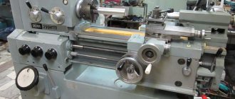
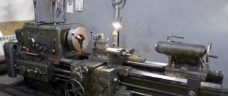
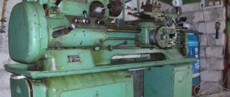
Technical characteristics, description and passport 16K20
16K20 Screw-cutting lathe is a universal equipment for precise processing of metal products in full compliance with international quality standards. The objective advantages of machines of this type include convenient operation, wide functionality and excellent performance indicators, which guarantee high results and maximum efficiency when used correctly in repair, production and other metalworking enterprises. As a rule, screw-cutting lathes are used to perform technological operations of varying complexity with the external and internal surfaces of parts, including rotating bodies that have a varied axis profile. In addition, the 16K20 lathe is very often used for quick and convenient cutting of left-hand and right-hand threads (metric, inch, modular and pitch), fully meeting the needs of enterprises in all sectors of modern industry. The screw-cutting lathe 16K20 has an expanded package that includes all the necessary equipment to ensure successful operation:
- gearbox
- electrical cabinet
- feed box
- headstock
- chuck guard
- bed
- carriage and support
- apron
- caliper guard
- tailstock
Feed box design of screw-cutting lathe 16K20
Machine feed box - unified unit 16B20P.070
and is a typical closed box design with movable units.
The connection between the spindle and the machine support to ensure optimal cutting mode is carried out using a feed mechanism consisting of a reversing device (bite) and a guitar, which change the direction and speed of movement of the support.
The feed box is mounted on the frame below the spindle (front) headstock and has several shafts on which movable gear blocks and switchable gear couplings are installed. In the right position of the clutch, the lead screw rotates, and in its left position (as shown in the figure), the drive shaft rotates through the overrunning clutch.
Feed box drawing for lathe 16k20
Feed box diagram for lathe 16k20
Adjusting the feed box of the machine 16K20
When repairing the machine, special attention should be paid to the correct installation of the gear shift mechanism mounted on plate 38, which is attached to the housing 3 of the feed box. In order to avoid disruption of the order of engagement of the gear wheels of the feed box during assembly, it is necessary to combine the marks marked on gears 51 and 52.