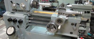
Homemade mini lathe from professional pipe (almost like a factory one)
In today's review, the author will share with us his personal experience of making a homemade mini lathe.
The basis of the machine is a square profile pipe 60x60 mm (wall thickness - 3 mm).
The dimensions of the professional pipe were not chosen by chance - it ideally fits a clamping chuck with a diameter of 16 mm. The result is a fairly compact headstock.
If you use a drill chuck with a diameter of 13 mm to make the headstock, then in this case you will need to use a 50x50 mm profile.
We also advise you to read: how to make a simple and compact machine for making clamps for reinforcement cages.
The length of the lathe bed is 22 mm, but if necessary it can be made longer.
Mounting methods
Making a homemade machine involves attaching two types of special holders, with the difference being how they are attached directly to the frame. If the motor has a stepper type, they use backlash-free nuts and flexible couplings, but craftsmen also come up with their own devices from scrap materials. The nut play can be eliminated with special bolts or connectors. The need for various types of fastenings is also determined by the diameter of the shaft.
Lead screw with nut
Manufacturers offer several mounting options. The feasibility of using homemade fasteners, given the availability and low cost of factory fasteners, is not only low, but also unsafe.
Making the headstock of a lathe
We start by making the headstock. The drill chuck acts as a spindle.
A steel boss 30 mm long and 32 mm in diameter (internal diameter 17 mm) will need to be welded to the back of the drill chuck.
The author turned the outer surface of the boss on a lathe to a diameter of 30 mm for bearing 6906.
The protruding part of the steel boss has a diameter of 20 mm and serves as a seat for the gear.
The front part of the drill chuck must be turned on a lathe to a diameter of 35 mm - for bearing 6907.
We put all the parts together and get a fairly compact chuck-spindle (for our machine this is exactly what we need).
The headstock housing consists of three main parts:
- flange with a diameter of 80 mm;
- a piece of professional pipe 65 mm long;
- square plate 8 mm thick.
The flange has a centering rim for a 60x60 mm profile, which has a seat for bearing 6906.
A square metal plate is driven into the end of the profile pipe (body) and scalded.
In this plate you will first need to drill and then bore a hole for the front bearing.
Thick metal plates are welded to the headstock body, into which mounting holes are drilled.
Main stages of work
In the bed of the lathe, the author cut a groove a little more than 10 cm long and about 8 mm wide. You also need to drill mounting holes according to the markings.
A strip of metal 8 mm thick is fastened inside the frame using M6 screws.
The craftsman drilled a series of holes in the profile pipe and the strip itself with a pitch of 20 mm. They are threaded M8.
The headstock is attached to the frame using four M6 screws. To tighten them, holes for a hexagon are drilled from the bottom of the frame.
It is also necessary to drill holes for M4 screws from the bottom of the frame. The base (steel plate 6 mm thick) is attached to the frame using screws.
Base dimensions - 220x95 mm. We drill mounting holes in the base for fastening to a table or other work surface.
The author made the next part from a turning tool (its width is 17 mm). This part is inserted into the frame and secured with four M4 screws.
Manufacturing of longitudinal and transverse feed
The main part of the longitudinal feed is made of a profile pipe 80x80 mm (with a wall thickness of 4 mm).
A part of the wall with sides 10 mm high is cut off from the profile pipe, to which a cheek is welded on one side. We drill a hole with a diameter of 8 mm in the cheek - for the passage of an M8 thread.
In a part made from a turning tool, the author drills a hole coaxial with the hole in the cheek.
After this, the drilled hole will need to be drilled to a diameter of 14 mm and an M16 thread cut.
The author used an M16 thread so that the feed pitch was larger (1 turn - 2 mm).
The author attaches a square rod (adjustable clamp) to the movable platform (from the inside).
The author made a cross-feed base from a piece of 40x20 mm profile pipe. The slot in it is made for an M6 screw. An extended M8 nut is inserted and welded inside.
The cross feed screw is a piece of M16 pin. At the end there is a groove with a diameter of M8 for the handle of an old sewing machine.
The longitudinal feed is pressed against the frame using a homemade clamp, which is located inside the frame.
We install the longitudinal feed on the base and secure it. Next, the transverse feed is made using the same principle, but from a piece of 50x50 mm profile (wall thickness - 2.5 mm).
A 6 mm thick metal plate is attached to the top of the cross feed (used to secure the tool holder).
The cross feed lead screw is made from an M8 stud. A groove was made on one side and an M6 thread was cut for a homemade flywheel.
Screw processing
The main parts on which the screw in the machine is based are the support journals and shoulders. The working surface of a screw is its thread. The greatest accuracy in a table vise and any other machines that have such a screw must be ensured between the working surface of the part, as well as the main basing surface. The technological basis for the production of a lead screw is its center hole. For this reason, in order to avoid deformation, the processing of all these surfaces is carried out using a movable rest. The use of this part determines the specific processing of the lead screw.
It is also important to note here that screws with different accuracy classes are processed to different values. Parts that will belong to 0,1 and 2 accuracy classes are processed up to the 5th quality. Screws belonging to the 3rd accuracy class are processed up to the 6th quality. Screws belonging to the 4th category are also processed up to the 6th quality, but at the same time they have a tolerance range for the outer diameter.
Assembly of all structural elements
We screw the frame to the base. We install the headstock, and then the longitudinal and transverse gears.
A 775 80W electric motor is used as a drive.
At the last stage, all that remains is to make the tailstock and secure it to the lathe bed.
A detailed review can be seen in the author's video (from YouTube channel IV I'm interested).
How to use a metal lathe
A modern industrial machine has a number of characteristics that allow it to perform many different operations. Such a device is equipped with a numerical program device and has a complex design. A DIY lathe does not require so many functions. It is enough to make a universal mechanical installation that will be conveniently placed on a table in the garage.
The main work performed on homemade milling equipment:
Safety precautions when working on lathes
- processing the internal surface, drilling the workpiece;
- turning a cone, groove;
- thread cutting;
- shaped turning;
- trimming ledges and sharp edges;
- turning of cylinders.
A metal lathe is used for machining nuts, bushings, couplings, pulleys, shafts and gears. From such parts, blanks are obtained that allow you to create or improve various mechanisms. Depending on the equipment used, the unit can process not only metal products, but also wooden or plastic blanks.
Screw quality indicators
The screw, as a very important part, must meet many requirements. In order for it to be used, for example, in a table vice, it must be suitable for such parameters as: diametrical size, profile accuracy and thread pitch accuracy, the ratio of the screw thread to its support journals, wear resistance, thread thickness. It is also important to note that, depending on the degree of movement accuracy that the screws provide, they can be divided into several accuracy classes from 0 to 4. For example, lead screws of metal-cutting machines must correspond to an accuracy class from 0 to 3. Accuracy class 4 is not suitable for use in such equipment.
Read also: Deep 300 machine diagram
Lathe design
A do-it-yourself metal lathe is a full-fledged piece of equipment with a power unit; it has a lot of weight and creates vibration. Before making such a device, it is necessary to carefully consider the design of all parts.
The mini-machine for home use has 4 main elements:
- Frame.
- Caliper and tool holder.
- Front and rear stock.
This unit is designed to fix all equipment in a rigid position. Being the basis, the frame must be strong and not distort. The machine can be placed on a table or a floor version can be made by increasing the length of the support. Such a cast frame is made from channels and metal corners. The frame elements are connected by welding or bolted.
Caliper
Such an element holds the cutting device and is capable of moving in a given direction and plane for efficient processing of workpieces. If it is necessary to create complex and non-standard surfaces, special attention should be paid to fastening this unit. For smooth movement in the horizontal direction, a screw mechanism in the apron is used. The support remains movable, but can be fixed if necessary. The cutters in the tool holder must be clamped tightly; backlash increases the risk of injury during operation.
Apron design for a universal screw-cutting lathe
The apron of the screw-cutting lathe is rigidly attached to the front end of the caliper carriage.
The apron converts the rotational movement of the lead screw or lead roller into translational movement of the caliper (feed) along the bed guides. The movement from the running roller is also used to mechanically move the cross slide.
A lead screw is used when cutting threads. The rotary motion of the lead screw is converted into a translational motion of the caliper (feed motion) using a split nut. The rotation speed of the lead screw, and therefore the feed rate, is controlled by the feed box of the lathe.
The roller is used for all other turning operations. The rotational movement of the running roller is converted into a translational movement of the caliper (feed movement) using a worm on a sliding key, a gear rack mounted on the frame and a gear engaged with the rack. This wheel can be rotated either mechanically - from the drive shaft, or manually from the rotation of the handle (handwheel).
Mechanisms in the apron can convert the rotational motion of the roller into translational motion (mechanical feed) of the caliper cross slide.
To accelerate the movement of the caliper, a separate electric motor is used, which rotates the roller at an increased speed.
A plunger pump provides lubrication of all drive parts, bearing supports and guides of the caliper and carriage. It is mounted on the lower cover of the apron and is driven by the worm gear shaft.
The lead screw is lubricated using a manual oiler with the nut on.
Step-by-step assembly of turning equipment with your own hands
A homemade lathe consists of parts that can be found in a garage or workshop. Before proceeding with the processing and assembly of the device, it is necessary to carefully consider the design and characteristics of the unit, its location in the workshop.
Necessary materials
You can use available materials as materials:
- welded frame (replaces the cast frame);
- power unit - any motor with an electric drive with a power of 800-1500 W from household appliances (a good option is an asynchronous motor);
- Belts of different lengths can be used as a driving stone;
- screws and nuts for fastening the structure;
- guides, slides made of steel rod;
- spindle and tailstock (it is better to find ready-made parts, but you can make them from a profile pipe or a piece of metal sheet);
- feed screws - for a do-it-yourself lathe, long rods with threads in the longitudinal and transverse directions are suitable;
- rolling bearings as rotation elements;
- squalls of different diameters;
- a steel plate with a thickness of at least 8 mm - for the caliper and tool holder.
Where to get a lathe project
Standard dimensions of turning equipment: 115x62x18 cm. Such parameters are considered optimal for work.
Drawing of a homemade lathe
Manufacturing process
Making a metal lathe with your own hands is carried out in accordance with the step-by-step guide for the main components:
The figure shows where and in what place the parts should be located correctly
- Formation of the frame according to the drawing data. The pipes are cut and welded together; it is important that the corners are even.
- Creating side posts (for this it is better to use another milling machine).
- Assembling the support unit, connecting the posts with the guides, installing spacer bushings on the sides.
- Fixing bushings for the tailstock. If you use these parts of different sizes, you can achieve more stroke.
- Creating a platform for the support.
- Mounting the lead screw, attaching the steering wheel and vernier to it.
- Installation of the headstock platform.
- Attaching the headstocks to the machine.
- Creating a support and tool holder.
- Formation of the engine subframe.
- Installation of the power unit and its connection to the electrical network.
- Test run at idle.
A DIY metal lathe is quite easy to make. It is important to maintain the design parameters, ensure a rigid connection and select a suitable electric motor.
What are nuts made of and how do they wear out?
The most common materials for the production of this type of parts are aluminum-iron bronze, according to machine tool building standards MT 31-2. In addition to this material, anti-friction cast iron can also be used as a substitute for non-critical screw gears.
It is important to add here that the nut wears out much faster than the lead screw itself. There are several reasons for this:
- the nut thread is poorly protected from any type of contamination, and it is also quite difficult to clean it of these unnecessary elements;
- it often happens that this element is initially poorly lubricated and this greatly affects its service life;
- when the nut engages with the screw, it turns out that all the turns of the second element work simultaneously, but the screw only has those that are engaged with the nut.
For these reasons, screws with nuts should be checked more often, since the nut wears out quite quickly.
How to make a homemade support for a lathe with your own hands?
In metal work, a lathe is used to produce cylindrical (conical) shaped parts. There are many models of this production device, and all of them have almost the same layout of similar components and parts. One of these is the machine support.
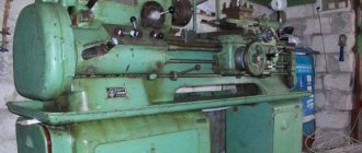
Homemade lathe
To better understand the functions performed by a lathe support, you can consider its operation using the example of the common 16k20 model. After reading this information, perhaps some home craftsmen will have the idea to create a homemade lathe for metal work with their own hands.
§ 21. Techniques for working on a screw-cutting lathe
One of the most common turning operations is the machining of external cylindrical surfaces. It is performed with passing incisors.
The workpiece must be fixed in the chuck so that its overhang is 7.12 mm greater than the required length of the part. This allowance is necessary for processing the ends and cutting the part.
The spindle rotation speed and depth of cut during turning are indicated in the technological map.
When setting the cutting depth, use the cross feed dial. In the TV-6 screw-cutting lathe, when this dial is rotated by one division, the cutter will be fed to a cutting depth equal to 0.025 mm (i.e., the price of dividing the transverse feed dial is 0.025 mm). The diameter of the outer surface of the part will decrease by 0.025 x 2 = 0.05 mm. The total number of divisions of the cutter feed dial α is determined by the formula: αtransverse = (D - d): 0.05, where D is the diameter of the workpiece, d is the diameter of the part.
After turning the outer cylindrical surfaces, the end of the workpiece is often trimmed. For this, various cutters are used.
When cutting the end with a passing (Fig. 72, a, b, c) or scoring (Fig. 72, d) cutter, bring it into contact with the end, then pull it back and move the carriage 1.2 mm to the left (i.e. set the cutting depth to 1.2 mm). By moving the cutter transversely, a layer of metal is removed from the end. You can move the carriage by 1.2 mm or any other amount using the longitudinal feed dial. The division price of this dial is 0.5 mm, therefore the number of divisions by which the dial needs to be rotated is determined by the formula: αlongitudinal = l: 0.5, where i is the required length of movement of the carriage.
Rice. 72. Trimming the ends with passing (a, b, c) and scoring cutters
If there is a hole at the end of the part, then trimming the end can be done from the center of the part by moving the cutter toward you (Fig. 72, c).
When processing small ledges, turning and trimming are performed with one persistent cutter.
External grooves are cut using slotted (groove) cutters. In this case, the cutting speed is set four to five times lower than when cutting the ends. The cutter is installed in the required place and smoothly, without much effort, moved in the transverse direction, removing chips. The depth of the groove is controlled by the transverse feed dial.
When cutting workpieces, they act in the same way as when cutting grooves. Finish cutting when the diameter of the jumper becomes equal to 2.3 mm. Then the machine is turned off, the cutter is removed from the slot and the part is broken off.
When processing parts on lathes and other machines, part of the metal turns into chips. At enterprises, the shavings are not thrown away, but are crushed in special devices and pressed into briquettes. These briquettes, together with scrap metal, are used in the smelting of steel and other metals and alloys.
Safe work rules
- You can measure the dimensions of the part, remove chips, clean and lubricate the machine only after it is completely turned off.
- The shavings should only be removed using a hook and brush.
Practical work No. 21
Grinding the outer cylindrical surface of a workpiece on a TV-6 machine
- Place and secure the workpiece in the chuck and the through cutter in the tool holder.
- Move the cutter towards the workpiece so that its tip is to the left of the end of the workpiece by 8.10 mm and at a distance of 2.3 mm from its surface.
- Turn on the spindle rotation and carefully move the cutter towards the workpiece until a slightly noticeable circular mark appears on its surface. Move the cutter to the right at a distance of 8.10 mm from the end of the workpiece and turn off the machine.
- Holding the handle for transverse movement of the caliper with your left hand, turn the dial ring with your right hand until its zero line aligns with the mark on the fixed bushing.
With both hands, turn the handle for transverse movement of the caliper to the required number of dial divisions (pre-calculated by you).
- Turn on the spindle rotation. Grind the workpiece to a length of 3.5 mm with manual feed of the caliper. Move the cutter away from the workpiece by turning the cross feed handle counterclockwise half a turn and move it to the right to its original position.
- Turn off the machine and measure the resulting diameter of the workpiece with a caliper. If the diameter is larger than required, calculate how many divisions you need to move the cutter to get the required diameter. Turn on the machine and remove chips in a test area. Repeat these steps until you reach the desired size.
- When you obtain the desired diameter, grind the workpiece along its entire length using manual or mechanical feed of the cutter. Move the cutter away from the surface being processed towards you and to the right to its original position.
Practical work No. 22
Trimming the end and drilling the workpiece on a TV-b machine
- Install and secure the cutter in the tool holder.
- Turn on the machine and trim the end of the workpiece (see Fig. 72) using the cross feed of the cutter. Turn off the machine, remove the part, secure it in a vice and clean the resulting ledge in the center of the end. Check the straightness of the end by applying a ruler to it.
- Install the part into the three-jaw chuck of the machine. Attach a center drill bit (or a short small diameter drill bit) to the chuck mounted in the tailstock quill. Turn on the machine and, rotating the tailstock flywheel, drill (center) the end to a depth of 2.3 mm. Remove the chuck from the tailstock quill.
- Install and secure the twist drill bit into the tailstock quill. Mark the required drilling depth with chalk on the drill bit. Turn on the spindle rotation and drill a hole in the workpiece to the specified depth by rotating the tailstock handwheel clockwise. Remove the drill from the hole and turn off the machine.
- Measure the depth of the drilled hole.
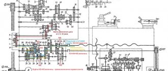
Description of operating modes of the machine apron
Fig. 9. Diagram of the apron of a screw-cutting lathe
Longitudinal feed of the caliper carriage
The longitudinal feed of the machine support when performing all turning operations, except for cutting threads with a cutter, is carried out using a gear rack 14 mounted on the frame and a gear wheel 17 rolling along it. This wheel can be rotated either mechanically - from the running shaft 1, or manually from the rotation of the handle . Mechanical longitudinal feed is carried out as follows. The long keyway 2 of the running shaft 1 includes the key of the worm 9 sitting on it. Rotating, the worm drives the worm wheel 8. To turn on the mechanical longitudinal feed, you need to use a handle 11 to connect (using a clutch) the worm wheel with the wheel 10. The latter will impart rotation to the wheel 15, and together with it the rack wheel 17, sitting on the same roller, will rotate. This wheel rolls along a stationary rack 14, driving the apron and the caliper carriage along the frame.
Manual longitudinal feed is performed by handle 13 through wheels 12, 15, 17 and rack 14.
Cross feed of caliper slide
To carry out mechanical transverse feed, a bevel gear 7 sits next to the worm 9 on the running shaft, the key of which also slides in the long keyway 2 of the running shaft 1. Rotating with the shaft, the wheel 7 rotates another bevel gear 4 and cylindrical wheels 5, 3, 6 and 21. Using the button 18, you can engage the wheel 21 with the wheel 19. Together with the wheel 19, the screw 20 rotates, carrying out the transverse feed of the cutter. To turn off the cross feed, wheel 21 is disengaged from wheel 19 using the same button 18.
Manual transverse feed is performed by handle 16.
Thread cutting on a screw-cutting lathe
Rice. 10. The device of a split nut (uterine nut) of a screw-cutting lathe
To move the caliper longitudinally when cutting threads, a lead screw 22 is used, to which is connected a split nut (male nut) 23 installed in the apron.
The split nut structure is shown in Fig. 10. When cutting a thread, both halves of the nut 23 are brought together using the handle 25; approaching, they capture the thread of screw 22, during the rotation of which the apron, and with it the support with the cutter, receive longitudinal movement. To move and move apart the halves of the split nut, a disk 24 with two spiral slots 26 is attached to the shaft of the handle 25, into which the fingers 27 of the lower and upper halves of the nut 23 enter. When the disk 24 is rotated, the slots force the fingers, and therefore the halves of the nut, to move closer or further apart.
§ 21. Techniques for working on a screw-cutting lathe
One of the most common turning operations is the machining of external cylindrical surfaces. It is performed with passing incisors.
The workpiece must be fixed in the chuck so that its overhang is 7.12 mm greater than the required length of the part. This allowance is necessary for processing the ends and cutting the part.
The spindle rotation speed and depth of cut during turning are indicated in the technological map.
When setting the cutting depth, use the cross feed dial. In the TV-6 screw-cutting lathe, when this dial is rotated by one division, the cutter will be fed to a cutting depth equal to 0.025 mm (i.e., the price of dividing the transverse feed dial is 0.025 mm). The diameter of the outer surface of the part will decrease by 0.025 x 2 = 0.05 mm. The total number of divisions of the cutter feed dial α is determined by the formula: αtransverse = (D - d): 0.05, where D is the diameter of the workpiece, d is the diameter of the part.
After turning the outer cylindrical surfaces, the end of the workpiece is often trimmed. For this, various cutters are used.
When cutting the end with a passing (Fig. 72, a, b, c) or scoring (Fig. 72, d) cutter, bring it into contact with the end, then pull it back and move the carriage 1.2 mm to the left (i.e. set the cutting depth to 1.2 mm). By moving the cutter transversely, a layer of metal is removed from the end. You can move the carriage by 1.2 mm or any other amount using the longitudinal feed dial. The division price of this dial is 0.5 mm, therefore the number of divisions by which the dial needs to be rotated is determined by the formula: αlongitudinal = l: 0.5, where i is the required length of movement of the carriage.
Rice. 72. Trimming the ends with passing (a, b, c) and scoring cutters
If there is a hole at the end of the part, then trimming the end can be done from the center of the part by moving the cutter toward you (Fig. 72, c).
When processing small ledges, turning and trimming are performed with one persistent cutter.
External grooves are cut using slotted (groove) cutters. In this case, the cutting speed is set four to five times lower than when cutting the ends. The cutter is installed in the required place and smoothly, without much effort, moved in the transverse direction, removing chips. The depth of the groove is controlled by the transverse feed dial.
When cutting workpieces, they act in the same way as when cutting grooves. Finish cutting when the diameter of the jumper becomes equal to 2.3 mm. Then the machine is turned off, the cutter is removed from the slot and the part is broken off.
When processing parts on lathes and other machines, part of the metal turns into chips. At enterprises, the shavings are not thrown away, but are crushed in special devices and pressed into briquettes. These briquettes, together with scrap metal, are used in the smelting of steel and other metals and alloys.
Safe work rules
- You can measure the dimensions of the part, remove chips, clean and lubricate the machine only after it is completely turned off.
- The shavings should only be removed using a hook and brush.
Practical work No. 21
Grinding the outer cylindrical surface of a workpiece on a TV-6 machine
- Place and secure the workpiece in the chuck and the through cutter in the tool holder.
- Move the cutter towards the workpiece so that its tip is to the left of the end of the workpiece by 8.10 mm and at a distance of 2.3 mm from its surface.
- Turn on the spindle rotation and carefully move the cutter towards the workpiece until a slightly noticeable circular mark appears on its surface. Move the cutter to the right at a distance of 8.10 mm from the end of the workpiece and turn off the machine.
- Holding the handle for transverse movement of the caliper with your left hand, turn the dial ring with your right hand until its zero line aligns with the mark on the fixed bushing.
With both hands, turn the handle for transverse movement of the caliper to the required number of dial divisions (pre-calculated by you).
Practical work No. 22
Trimming the end and drilling the workpiece on a TV-b machine
- Install and secure the cutter in the tool holder.
- Turn on the machine and trim the end of the workpiece (see Fig. 72) using the cross feed of the cutter. Turn off the machine, remove the part, secure it in a vice and clean the resulting ledge in the center of the end. Check the straightness of the end by applying a ruler to it.
- Install the part into the three-jaw chuck of the machine. Attach a center drill bit (or a short small diameter drill bit) to the chuck mounted in the tailstock quill. Turn on the machine and, rotating the tailstock flywheel, drill (center) the end to a depth of 2.3 mm. Remove the chuck from the tailstock quill.
- Install and secure the twist drill bit into the tailstock quill. Mark the required drilling depth with chalk on the drill bit. Turn on the spindle rotation and drill a hole in the workpiece to the specified depth by rotating the tailstock handwheel clockwise. Remove the drill from the hole and turn off the machine.
- Measure the depth of the drilled hole.
Principles of turning materials
Turning of materials involves processing bodies of revolution with a cutting tool moving along the axis of rotation of the workpiece.
With the forward movement of the cutter, a layer of material is removed from the surface of the workpiece. Historically, processing of “round” parts was required in almost all sectors of the national economy. The first lathes were very primitive: the workpiece was rotated using a foot drive, and the cutting tool was held in the hands with emphasis on a stand. Such machines could only process soft materials, such as wood. Lathe of Peter I. At the end of the 19th century, with the advent of machines, steam and then electric engines began to be used to rotate the workpieces. An important achievement of that time was the development and introduction of cutting tool holders. The tool was fixed in a special holder, and the operator could move the holder both parallel and perpendicular to the workpiece by rotating certain handles. Such devices became known as “lathe support.”
A lathe from the early 20th century.
Modern lathes allow you to automatically move the cutting tool in specified directions. The advantages of modern lathes also include the ability to cut threads of almost any profile and a given accuracy. That’s why modern machines are called “screw-cutting lathes.”
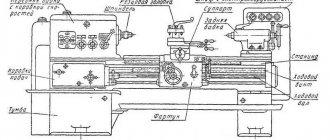
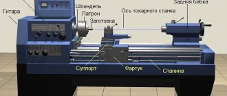
The structure and main components of a lathe.
Most lathes have almost the same design and differ only in size and location of controls. The figure shows a typical lathe and its main components. The axis of a lathe
is a virtual axis passing through the axis of rotation of the workpiece parallel to the bed.
The front stand and rear stand
are cast iron stands that serve as stands for the components and mechanisms of the machine.
Tabletop machines do not use cabinets. The bed
is the main part, the skeleton of the lathe.
The bed is usually made of all-metal by casting from cast iron. The bed is attached to the stands of the machine. The large weight of the bed reduces vibrations from the electric drive of the machine and vibrations that occur during the processing of parts. An electric drive motor is installed at the bottom of the bed, inside or behind the lathe. Electrical cabinet
- a cabinet in which elements of the electrical circuit of the machine are located, and on the outer panel there are switches for the main electric motor, a compressor for coolants, a voltmeter and indicator lights.
Headstock
- contains a set of gears, levers, shafts and mechanisms for changing the speed of rotation of the workpiece and the feed rate of the cutting tool.
The guitar
is an integral part of the headstock, which contains replaceable gears for adjusting the tool drive when cutting threads (in modern machines, changing gears is not required).
Spindle
is the main shaft for rotating the workpiece.
The spindle can accommodate fastening devices such as a chuck, a center, a collet, and the like. The chuck
is the most common workpiece fastening device.
A caliper
is a device for attaching a processing tool and moving the tool in specified directions.
The apron
is the front caliper cover.
Tailstock
is a device for fastening a workpiece (when processing in centers), or for fastening tools, such as a tap, a die when cutting threads and other devices.
Headstock
On the front surface of the headstock there are levers for switching the spindle rotation speed and cutting tool feed speed. Nameplates
are explanatory signs.
On lathes, the nameplates indicate the dependence of the speed of movement or rotation of machine components on the selected positions of the installation handles. Spindle speed knobs
- depending on the position of these knobs, the spindle rotation speed changes.
The handles can only be moved when the machine is stopped. Dividing lever
- Lever for switching the spindle speed.
The lever has three positions. In the extreme left position, the machine spindle rotates at the normal speed set by the spindle speed adjustment knobs. In the vertical (neutral) position, the spindle does not rotate. In the extreme right position, the spindle rotates at a speed 10 times lower than the set one. This lever can only be switched when the machine is stopped. Handles for setting the feed speed
- these handles set the speed of movement of the cutting tool when processing parts, as well as the movement of the cutting tool per revolution of the spindle when cutting threads.
The handles can only be moved when the machine is stopped. The spindle
is a thick-walled steel pipe. The spindle is used to transmit rotation from an electric drive, through a gear system, to the workpiece. The spindle inlet on the surface is threaded for mounting mounting chucks, and the inlet hole is cone-shaped for installing centers or other fasteners. It should be noted that for different machine models, the number and position of the rotation speed and movement adjustment handles may differ from those shown in the figure. For a specific model of lathe, you should carefully read the designations on the nameplates or read the operating instructions for the machine.
Tailstock
Tailstock
is a device for fastening a workpiece (when processing in centers), or for fastening tools, such as a tap, a die when cutting threads;
drill bits or drill chuck when drilling holes. The base
is a part of the tailstock, its skeleton.
The base and, consequently, the entire tailstock can move freely in a horizontal plane along the frame along the axis of the machine. The tailstock housing is attached to the base. The tailstock housing
is a unit containing the functional mechanisms of the tailstock.
Tailstock position adjustment screw
- designed to slightly move the tailstock body in a horizontal plane in transverse directions.
It is used in cases where it is necessary to align the center of the workpiece with the center of the tailstock (make it coaxial) or when processing conical parts. A quill
is a movable steel cylinder.
The inlet hole of the quill has a conical shape and is intended for fastening mandrels, fixtures, centers, etc., depending on the work being performed. Quill fixation handle.
When operating a lathe, vibrations may occur that lead to spontaneous movement of the quill.
To fix the quill in a given position, the fixation handle is used. Quill movement wheel
- when this wheel rotates clockwise, the quill moves out of the tailstock housing, and when the wheel rotates counterclockwise, the quill goes inside the tailstock housing.
Tailstock locking handle.
To move the tailstock along the bed, the locking handle should be released (move the handle back). To fix the tailstock, after moving it, the locking handle should be pulled towards you until it stops. In this case, the tailstock will be fixed in the desired position and will not be able to spontaneously move along the bed due to loads on the quill or parasitic vibrations.
Caliper
The lathe support is designed to secure and move the cutting tool. A rotary tool holder
is a device for securing and changing a cutting tool.
The tool holder fastening handle
is intended for changing the cutting tool.
To change the tool, the handle is turned counterclockwise (away from you), while the tightening head loosens the fixation of the tool holder and it rotates. To fix the tool holder, turn the tool holder fastening handle clockwise (towards you) until it stops. The upper slide
is a mechanism for moving the tool holder in a given direction.
The upper slide can be rotated (in a parallel plane) relative to the machine axis at a given angle. This will be discussed in detail in the topic “Processing of conical surfaces”. Top Slide Move Handle
- Rotating this handle moves the top slide horizontally.
Cross slide
- designed to move the cutting tool in a horizontal plane strictly perpendicular to the axis of the machine.
Cross slide movement handle
- rotating this handle clockwise moves the cross slide forward (towards the axis of the machine), and counterclockwise backwards (away from the axis of the machine).
Longitudinal slide
- a device for moving the cutting tool strictly parallel to the axis of the machine.
Slider Wheel
- Rotating this wheel counterclockwise moves the cutting tool horizontally from right to left, and clockwise moves it from left to right.
Screw feed switch
- used only when cutting threads with a cutter.
In all other modes of part processing, this switch is disabled. Feed switch
- multi-position lever to enable automatic movement of the cutting tool in a given direction. In position 0 - (neutral) the caliper stands still; in positions 1 or 2, the cross slide moves (forward or backward, respectively); in position 3 or 4, the longitudinal slide moves (to the left or to the right, respectively). Feed switches can have a different design, for example, have two levers. One includes longitudinal and the other transverse feed.
Drive shafts and mechanisms
To automatically move the support elements, as well as to quickly turn on and off the spindle rotation, the lathe is provided with several drive shafts and corresponding mechanisms.
The switching and switching mechanisms for various drives are located in the caliper under the apron. Spindle activation shaft
— has two handles for turning on the spindle.
One handle is located to the left of the machine operator, and the second to the right. Both handles are rigidly fixed to the shaft. When any of these handles is moved up, the machine is turned on and the spindle begins to rotate counterclockwise (working, forward rotation). In the middle position of the handles, the machine is turned off. When the handles are moved down, the spindle begins to rotate clockwise (reverse rotation). The rack
is an integral part of the mechanism for manually moving the caliper in the longitudinal direction.
When the wheel of movement of the longitudinal slide rotates, the gear wheel connected to the axis of rotation of the wheel and the gear rack engages, and the caliper moves. Feed Shaft
- This shaft is designed to automatically move the cutting tool.
The shaft has a longitudinal groove along its entire working length, which serves to engage with the movement mechanism. When the machine is running, this shaft rotates constantly. The feed switch knob turns on the mechanism of the selected movement. Threaded shaft (Screw)
- designed to drive the caliper in the longitudinal direction when cutting threads with a cutter. The rotation of this shaft occurs only in thread cutting mode.
Limbo
A limb is a ring (or flat washer) with marks printed on its surface, located at equal distances from each other.
At a certain interval, for example, every 10 marks, numbers are printed indicating a certain value of the dial graduation. The dial can be graduated in millimeters, degrees or other metric units. The figure shows a dial located on the mechanism for moving the cross slide. The rotation of the dial occurs together with the rotation of the tool movement handle. Every tenth of the risk on the dial is numbered 0, 1, 2 ..19. In total, the limb has 200 marks. In this case, when you turn the handle, for example, by 10 divisions (from 0 to 1), the working tool will move 1 millimeter. Different machines have different dial calibrations, so you should consult the operating instructions for the specific machine. If it is not possible to find out this information, then you can determine the amount of movement yourself. To do this, you should grind the part and measure the resulting size, then grind the part again by turning the handle ten divisions and again measure the size obtained after turning. The difference between the previous and last measurement will be the amount of movement of the tool when rotated by 10 divisions. The dial ring can be rotated on the mechanism axis by holding the movement handle. This may be necessary to set the reference point during processing; usually the value is set to 0.
Main types and characteristics of lathes
Lathes have certain characteristics that should be taken into account when manufacturing certain parts on them: Machining diameter over the bed D
- the maximum diameter of the workpiece that can be installed and processed on the machine.
| The distance between centers L is the maximum length of the workpiece that can be installed and processed on the machine. |
| The diameter of the spindle hole d is the diameter of the hole through which the workpiece (rod) can pass. |
More information about the types of modern machines can be found on the website