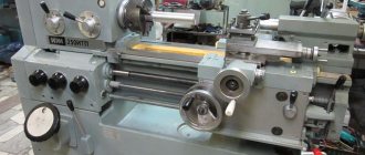
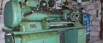
Screw-cutting lathe 1K625D
The 1K625 screw-cutting lathe was created by the design bureau of the Moscow Machine Tool Plant based on the 1K62 machine. The reason for this was the need in the engineering industry for medium-sized turning equipment capable of processing longer workpieces.
Compared to the base model, all 1K625 variants have increased center dimensions by a third and maximum processing diameters by a quarter. Both machines were produced from the second half of the fifties to the beginning of the seventies and were replaced in the production line by the 16K20 family. 1K625 was produced in three standard sizes and, depending on the equipment, has several modifications.
Specifications
The 1K625 size range includes three types of machines with lengths along the center-to-center axis from 1000 to 2000 mm: In addition to turning and boring, processing with a rotating tool and four types of threading, the machine can perform cutting of an Archimedean spiral. The main technical characteristics of the 1K625 screw-cutting lathe are as follows (all dimensions in mm):
- processing height above the guides - 250;
- processing height above the carriage - 130;
- maximum length of the workpiece - up to 2000;
- maximum turning length - up to 1920;
- maximum turning diameter of a bar is 45;
- maximum spindle speed - 2000 rpm;
- main engine power - 10 kW.
At the request of the customer, the machine could be equipped with a conical ruler, as well as a hydrocopying support (instead of the standard one). In addition, 1K625 with the index “G” was produced, in which a recess was made in the left part of the bed to increase the turning diameter of disk-type parts .
Description and purpose
The 1A625 screw-cutting lathe is used to perform a large range of turning operations. It is not advisable to use it for roughing or rough turning. The kinematics of this equipment provides the following spindle speeds (11.5 ... 2000 rpm) and allows turning at high speeds using carbide cutters.
It allows you to cut basic types of threads.
The gearbox control is designed in such a way that control of rotation speeds has become much easier than on other equipment of this class. Moreover, work can be performed on this equipment in two speed ranges.
A tapered ruler mounted on a support ensures the production of cone-shaped surfaces
To adjust this equipment, it is necessary to set the control handles with pointers on them that point to the required parameters. This control eliminates the need to perform additional calculations and use lookup tables.
Key controls are located in front, on the headstock, in places convenient for the turner.
The delivery set includes steady rests that allow you to process long workpieces.
To process workpieces, they are clamped into a lathe chuck, fixed at the end of the spindle or clamped in the center. One of which is installed in the spindle, and the second in the tailstock.
Specifications
The main technical parameters of this equipment include the following:
Maximum diameters of workpieces when turning above, mm:
- bed - 500;
- caliper - 290;
- RMC - 1000, 1500, 2000.
Spindle
The diameter of the hole made in the spindle body is 56, and the maximum size of the processed rod (hexagonal, round, etc.) is 54 mm.
Spindle rotation speed in the forward direction is 11.5 – 2000 rpm, in the reverse direction 14 – 2400 rpm. Number of speeds 15.
Caliper
The support can move both along the frame and across it. Moreover, in the first case it can move by 1000, 1500, 2000, in the second by 325 mm. The upper support, which is designed to fix the cutting tool, can move 150 mm.
Electrical part
This equipment includes three electric motors, kW:
- main drive - 10;
- fast movements – 0.6;
- pumping station – 0.125.
Dimensional and weight parameters
Machine dimensions, mm 2820*1202*1280. The weight of the equipment is 2820 kg.
Lathe 1k625 - technical specifications
Acceptable dimensions of parts for processing:
- The diameters of the workpieces are 500 (above the bed), 260 (above the support) and 45 mm (in the spindle cavity).
- The length of the parts is 1000, 1400 or 2000 mm (depending on the modification of the equipment).
- The number of thread types is 44 metric, 38 inch, 20 modular, 37 pitch and 5 Archimedes spirals.
Weight and dimensions depending on the version:
- Dimensions 3200 * 1200 * 1350 mm (with center-to-center length 1000 mm).
- Weight 2410 kg.
Power consumption from the network is 10 kW.
1K625 machine characteristics
Buy this machine without intermediaries:
Specifications:
Model 1k625 machines are designed to perform a variety of turning operations, including cutting threads: metric, inch, modular, pitch and Archimedean spiral.
Largest turning diameter above the bed, mm 500 Largest turning diameter above the support, mm 260 Hole diameter in the spindle, mm 47 Distance between RMC centers, mm 1000, 1400, 2000 Longest turning length (respectively RMC), mm 930, 1330, 1920 Limits of numbers spindle revolutions, rpm 12.5 – 2000 Limits of longitudinal feeds of the support, mm/rev 0.07 – 4.16 Limits of transverse feeds of the support, mm/rev 0.035 – 2.08 Limits of pitches of cut threads: Metric, mm 1 – 192 Modular, modules 0.5 – 48 Inch, number of threads per inch 2 – 24 Pitch, pitches 1 – 96 Main electric motor power, kW 7.5(10) Machine dimensions, mm (length x width x height) RMC 1000 mm 2812 x 1216 x 1349 RMC 1400 mm 3212 x 1216 x 1349 RMC 2000 mm 3812 x 1216 x 1349 Machine weight, kg RMC 1000 mm 2310 RMC 1400 mm 2410 RMC 2000 mm 2635
Buy this machine without intermediaries:
mashinform.ru
Passport for the machine
The “Technical and Operational Passport” of each screw-cutting lathe 1K625 contains a detailed description of all the technical characteristics of the copy shipped to the customer, including:
- parameters of drives and friction couplings;
- specifications for gears, worm wheels, screws and nuts;
- list and description of control knobs;
- tables of machine time and machine productivity when performing standard operations;
- actual characteristics of accuracy and rigidity;
- list of additions and changes;
- specification for the lubrication scheme;
- specification for the circuit diagram;
- list and description of bearings.
The final part of the “Passport” is the four-page “Certificate of technical testing and acceptance of the machine”, at the end of which the test results are given, confirmed by the signatures of the workshop manager and the head of the quality control department. Appendix N1 lists the accessories and fixtures supplied with the machine, and Appendix N2 contains a list and drawings of wearing parts.
Screw-cutting lathe 1K625D
The 1K625D screw-cutting lathe is designed to perform a variety of turning operations, including cutting threads: metric, inch, modular, pitch and Archimedean spiral.
Turning of a variety of materials can be carried out under impact load without changing the accuracy. The high power of the main drive of the machine, the high rigidity and strength of all links of the kinematic chains of the main movement and feeds, vibration resistance, a wide range of speeds and feeds make it possible to perform high-performance cutting with carbide and mineral-ceramic tools on the 1K625D RMTs=1500 screw-cutting lathe.
Download the passport for the screw-cutting lathe 1K625D
Technical specifications for screw-cutting lathe 1K625D
| Accuracy class according to GOST 8-82 | H |
| The largest diameter of the workpiece being processed, mm: above the bed above the support | 500 290 |
| Maximum length of workpiece processed, mm | 1500 |
| Maximum stroke length of the carriage, mm | 1430 |
| Size of the internal cone in the spindle, M | Morse 6 M80* |
| Spindle end according to GOST 12593-72 | 6K, 6M* |
| Diameter of through hole in spindle, mm | 55, 62* |
| The largest mass of the workpiece being installed, kg fixed in the chuck fixed in the centers | 300 1300 |
| Number of speed steps of direct reverse spindle | 23 12 |
| Spindle speed limits, min. direct reverse | 12,5-2000 19-2420 |
| Number of stages of working feeds: longitudinal transverse | 42, 56* 42, 56* |
| Limits of working feeds, mm/rev longitudinal transverse | 0.07-4.16 0.035-2.08 |
| Number of threads to be cut, units: metric inch modular pitch Archimedean spiral | 45, 53* 28, 57* 38 37 5 |
| Limits of pitches of cut threads: inch, number of threads per inch metric, mm modular, pitch module, pitch of Archimedean spiral, inch of Archimedean spiral, mm | 24…1.625 0.5-192 0.5…48 96..1 3/8”, 7/16” 8, 10, 12 |
| Maximum torque, kNm | 2 |
| Maximum movement of the quill, mm | 200 |
| Transverse displacement of the housing, mm | ±15 |
| Largest cutter section, mm | 25 |
| Overall dimensions of the machine, mm length width height | 3286 1221 1500 |
| Machine weight, kg | 3484 |
| Machine drive | |
| Main motion drive electric motor power, kW | 11 |
| Electric motor power for fast movement of the caliper, kW | 0.75 or 1.1 |
| Cooling pump power, kW | 0.12 |
1k625 characteristics
The technical characteristics of the machine model 1K625 allow you to perform finishing and semi-finishing various turning operations in small-scale and individual production, as well as producing threads: metric, modular, inch, pitch and Archimedean spirals.
| Characteristic name | Unit measurements | Options |
| Largest turning diameter above bed | mm | 500 |
| Largest turning diameter above slide | mm | 260 |
| Spindle hole diameter | mm | 47 |
| Distance between centers - RMC | mm | 1000 |
| mm | 1400 | |
| mm | 2000 | |
| Maximum turning length (according to RMC) | mm | 930, 1330 |
| Spindle speed limits | rpm | 2,5 – 2000 |
| Limits of longitudinal feeds of the caliper | mm/rev | 0,07 — 4,16 |
| Caliper lateral feed limits | mm/rev | 0,035 — 2,08 |
| Number of cutters in the tool holder | 4 | |
| Largest cutter holder dimensions | mm | 30 x 30 |
| Height from the cutting surface to the center line | mm | 30 |
| The greatest distance from the center line to the edge of the tool holder | mm | 268 |
| Number of front calipers | 1 | |
| Number of rear tool holders | 1 | |
| Number of cutting heads in the caliper | 1 | |
| The greatest movement of the caliper by hand, along the drive shaft, along the lead screw: | ||
| longitudinal (respectively RMC) | mm | 930 |
| mm | 1330 | |
| mm | 1920 | |
| transverse | mm | 300 |
| Number of switching stops | ||
| longitudinal stroke | 1 | |
| cross stroke | — | |
| Rapid movement speed of the caliper: | ||
| longitudinal | m/min | 3,4 |
| transverse | m/min | 1,7 |
| The price of one division of the dial: | ||
| longitudinal movement | mm | 1 |
| lateral movement (per diameter) | mm | 0,05 |
| Maximum rotation angle | hail | -65°+45° |
| The price of one division of the rotation scale | 1° | |
| Maximum displacement | mm | 140 |
| The price of one case is blue limb | mm | 0,05 |
| Landing cone in the spindle | Morse No. 6 | |
| Hole diameter | mm | 47 |
| Spindle braking | There is | |
| Landing cone in quill | Morse No. 5 | |
| Maximum quill movement | mm | 200 |
| The price of one division of the quill movement dial | mm | 0,05 |
| Lateral offset | ||
| forward | mm | 15 |
| back | mm | 15 |
| Metric | mm | 1 – 192 |
| Modular | modules | 0,5 — 48 |
| Inch | threads per inch | 2 — 24 |
| Pitchevykh | pitches | 1 — 96 |
| Main motor power | kW | 7, 5(10) |
| Machine dimensions, mm (length x width x height) | ||
| RMC 1000 | mm | 2812 x 1216 x 1349 |
| RMC 1400 | mm | 3212 x 1216 x 1349 |
| Machine weight, kg | ||
| RMC 1000 | mm | 2310 |
| RMC 1400 | mm | 2410 |
www.stanoktehpasport.ru
Overall dimensions of the workspace
Dimensional restrictions when processing a product on a lathe depend on its geometric characteristics, the main of which are the value of the center-to-center distance, as well as its height above the lower surface of the support and guides (for machines with a recess, above its lower plane). 1K625 was produced in three options for center-to-center distance with the following maximum restrictions on turning length: 930, 1330, 1920 mm, and the maximum machining height above the guides and the lower surface of the support for all three options is, respectively: 250 and 130 mm.
Repair features
Most often, situations arise when a simple inspection and maintenance of the machine is not enough and it must be taken out of the production cycle and transferred for repair. The reason for repair may be wear of the guides on the frame, on the caliper, bearings, breakage of forks intended for shifting gears, loss of accuracy when processing parts. In addition, a loss of alignment between the spindle and the tailstock may be a reason for carrying out repair work.
The reason for taking the machine out for repair may be the results of tests for axial and radial runout. These tests must be carried out in strict accordance with the requirements of the operating instructions.
To diagnose rolling bearings, a test piece is processed and the results are compared with the requirements. Often, such checks and implementation of the necessary preventive measures help postpone major repairs.
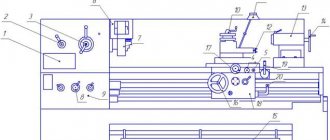
List and location of controls
The main spindle controls are located on the headstock, and the high speed and working feed controls are on the apron and caliper. The following handles and levers are located in a row on the front of the headstock:
- selection of spindle speed;
- setting thread parameters;
- thread and feed directions;
- spindle speed switching.
Below them is a feed box, on which there are two handles: selecting and turning on linear and threaded feeds.
The main controls on the apron are a manual steering wheel, a push-button station, and a high-speed lever. On the support there are handles for longitudinal and transverse feeds, as well as a lever for positioning and fixing the cutter holder.
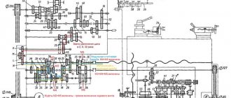
Headstock
In the headstock of the 1K625 machine there is a spindle assembly with a gearbox. The movement to it comes from the main engine through a drive pulley and is further distributed through a gear system to the spindle and the feedbox located below. A clamping chuck is attached to the left end of the spindle, through which the workpiece rotates.
Tailstock
The tailstock of the 1K625 machine is used for supporting long parts and fastening rotary tools. It can be moved manually towards the spindle and back, and can also be moved across the longitudinal axis. The latter are used in cone turning of long workpieces. The main component of the tailstock is a hand-operated quill with a cone for setting centers and rotary tools. The tailstock is fixed to the guides manually with a bolt and shoe.
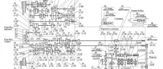
Gearbox
The feed box is mounted in a recess in the frame, which is located below the headstock. Rotation is supplied to it through a system of replaceable gears from the gearbox. The movement is then transmitted through the lead screw and the lead shaft to the apron. Then it is transmitted to the caliper by the gear mechanism of the apron.
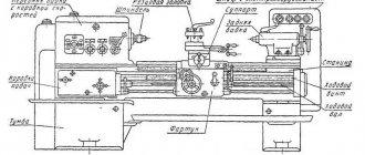
Design Features
The bed is a cast part on which the main components of the machine are placed. The caliper and tailstock move along it. To ensure their movement, the frame has guides that have undergone heat treatment and grinding. This processing makes it easier to move these units.
The bed is fixed on two pedestals installed on a reinforced concrete foundation.
The main drive motor is mounted in the left cabinet.
Apron - with the help of this unit, the rotation of the drive shaft is converted into caliper movement.
Caliper – ensures the movement of the tool holder in different planes. The cutter can be moved either under the control of a mechanism or manually. This unit includes:
- carriage;
- drive shaft;
- tool holder
It is possible to secure four cutters in the tool holder; in addition, it is possible to install other tools and technological equipment.
A protective screen is mounted on it, protecting the worker and the surrounding area from flying chips.
The tailstock is needed for installing long workpieces, securing core tools (drills, countersinks, etc.) and technological equipment (centers). A quill is installed in the tailstock housing. Its purpose is to fix the tool and centers, both rotating and solid. To extend the quill, a steering wheel is installed in the rear part, which, through a screw pair, extends it or returns it to its place.
Sometimes, to facilitate movement, compressed air is supplied under the base of the tailstock.
Fixing the tailstock in the right place on the bed is done using a lever mechanism.
The electrical cabinet is responsible for starting the electric motor and starting and stopping the machine. An electrical supply of 380 V is supplied to it. Inside the cabinet, automatic switches and safety devices are installed to protect the electrical part of the machine.
Electrical equipment
Over the many years of production, the electrical circuit of the 1K625 machine has remained virtually unchanged. But since it was produced for almost two decades, the element base of machines from different years can differ significantly. The electrical equipment of the machine has two versions: normal and tropical.
The machine is powered from the following AC sources:
- power circuits - 3 x 380 V (optional - 220 V);
- monitoring and control equipment - 110 V;
- lighting fixtures - 24 or 36 V.
The 1K625 lathe has three types of electrical equipment protection:
- fuse links (from short circuit currents);
- thermal relays (from overloads of electric motors);
- starters with zero protection (against voltage drop).
There are four electric motors on the machine: the main motor, the quick move motor, the hydraulic support pump and the coolant pump. All control and monitoring electrical equipment is mounted in an electrical cabinet, which is installed on the right at the rear of the frame.
The procedure and frequency of inspection and maintenance of electrical equipment 1K625 are described in detail in its “Care and Maintenance Manual”. For example, technical inspection of engines should be carried out at least once every two months, in which case it is necessary to clean the engines from contamination and check the reliability of electrical connections and grounding.
Purpose and scope
According to the “Care and Maintenance Guide,” the 1K625 lathe is designed for “finishing and semi-finishing ... turning work” in “small-scale and individual” production. In addition to the range of products characteristic of equipment of this type, the technical characteristics and equipment options of the 1K625 made it possible to use it for the following types of work:
- small-scale production of parts with complex surface profiles using a hydraulic copying support;
- processing long workpieces in centers using steady rests;
- turning long flat cones using a tapered ruler;
- cutting Archimedes' spirals on long blanks.
In addition, at the customer’s request, the 1K625 machine could be supplied with a recess in the bed, which made it possible to process disk-shaped parts with a diameter of up to 700 mm.