16K25B - basic machine of normal accuracy;
It should be remembered that in the process of technical improvement of 16K25B lathes, some changes may be made to their design. Therefore, when ordering spare parts, the following information must be provided:
- The model and serial number of the machine are indicated on the plate placed on the spindle head;
- It is advisable to purchase components (bearings, electrical equipment, etc.) according to the type or number printed directly on them indicating the basic data.
- If this is not possible, the type or number can be determined using the diagrams and tables in the manual.
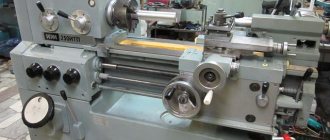
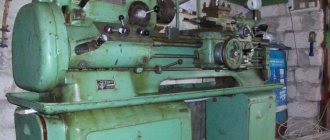
Controls of the machine 16K25B
Controls of the machine 16K25B.
- Feed rate table
- Thread type selection knob
- Spindle speed selection knob
- Emergency stop button
- Main motor start button
- Chuck protective screen
- Three jaw chuck
- Feed speed selector knob
- Feed box oil indicator
- 4-position tool holder
- Lamp
- Flywheel for moving the upper carriage
- Tailstock
- Tailstock quill feed flywheel
- Emergency stop pedal
- Longitudinal caliper feed flywheel
- Toolholder cross feed mechanism
- Caliper apron
- Longitudinal and cross feed handle with quick feed button
- Spindle rotation switch.
Gearbox
An independent unit located above the left cabinet. Kinematics (see 3.2). The unit, coupled with a pitch increasing chain and a replaceable guitar, provides 24 longitudinal / transverse feeds.
Precision thread processing is provided, bypassing the mechanics of the box, with the screw disconnected. The start of the fast motion engine is accompanied by automatic shutdown of the drive shaft by the activated freewheel. In order to increase the durability of the supports, rolling bearings are used throughout. Lubrication of friction pairs is automatic, by watering, oil supply from a separate pump.
Rice. 6. Section of the box
Installing and removing the machine chuck 16K25B:
- When installing and removing the chuck, protect the guides and bed with wooden boards placed under the chuck. Hold the chuck while you loosen the 3 cam locks by rotating ¼ turn counterclockwise. Align the A marks with each other. Carefully remove the cartridge.
- Before starting installation, you should make sure that there are no nicks on the mating surfaces and thoroughly wipe them with a lint-free cloth. Install the chuck onto the front end of the spindle. Clamp the cam lock of the clamping eccentric by rotating clockwise. The clamping eccentric mark A (Fig. 5) must be located between the 2 marks B (Fig. 5). The accuracy of the chuck fit on the spindle is checked by an indicator using a control band located on the outer cylindrical surface of the chuck body. Radial runout should not exceed 0.02 mm. Fig.5 Installing and removing the machine chuck 16K25B.
- The fixed steady rest serves primarily to support long workpieces and ensures their reliable processing without vibrations; it is mounted on the frame using a fastening strip. *
- Install the steady rest crackers so that there is no gap between them and the workpiece and they do not pinch it. During processing of the part, it is necessary to lubricate the crackers well.
- The movable steady rest is installed on the longitudinal slide of the support and thus repeats the movement of the turning cutter. It prevents elastic deformation of long and thin workpieces under the pressure of a turning tool. When machining a workpiece, it is necessary to install the crackers in the same way as on a stationary rest.
History of creation
Once upon a time, a mill was a device consisting of two established centers. Between each of them a blank made of a wooden base, horn or bone was clamped. A special person worked on the machine. He was an apprentice or an ordinary slave.
He picked up the workpiece and rotated it. It was necessary to rotate some turns in one direction, and other parts in the opposite direction. The master also had a chisel in his hand, which had to be held, under no circumstances letting go in one place. The chips were removed from it, the workpiece gradually became similar to the object of the required format.
A little later, in order to obtain good quality workpieces, onions began to be used. A weak bowstring was pulled inside it. It was specially made to have a slightly sagging appearance. The string was wrapped around the workpiece (its cylindrical part). We tried to form something like a loop. When the bow moved in different directions, the beams split.
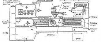
Unpacking and transporting the lathe 16K25B
Fig. 1. Scheme of transportation of the 16K25B lathe.
The lathe 16K25B is supplied on a pallet. When unpacking, care must be taken not to damage the machine with the unpacking tool. If upon unpacking you discover any damage that occurred during transportation, please notify the seller immediately. Do not operate the machine in this case.
Packing lists for accessories and tools are located in a separate box placed on the machine pallet.
Before transporting the 16K25B lathe unpacked, you must make sure that the moving components are securely fastened to the frame. The tailstock is fixed in the right extreme position, and the carriage is fixed in the middle part of the bed between the rope slings.
Transportation of the machine is carried out according to the transportation scheme (Fig. 1) using a four-line rope, ends 1 and 2 of which are put on two 60 mm steel rods. 3 (Fig. 1), inserted into specially provided holes in the base of the machine.
In places where the rope touches the machine, you need to install wooden spacers 4 (Fig. 1). When transporting to the installation site and when lowering it onto the foundation, it is necessary to ensure that the machine is not subjected to strong shocks and shocks.
Warranty and DIY repairs
High productivity and quality of work performed depend not only on the qualification category of workers. The main thing is that the device works stably and performs its functions. None of the workshops where mechanical products are processed can do without a lathe. But, unfortunately, they can also break.
The most common cause of malfunction of the 16D25 lathe is wear of the mechanism and motor system. After all, the device consists of many elements rotating among themselves. If an electrical fault occurs, the load must be reduced and checked for overheating conditions.
Repair work can be divided into several options. The most common of them are:
- the technical type helps ensure machine functionality between ongoing repair robots. This means that the equipment requires specific care. Repairs are carried out by mechanics on duty or machine operators;
- current type repair. It is carried out during the operational process. At the same time, a guarantee is provided for the continued operation of the 16D25 lathe;
- major renovation. It is performed if all equipment stops working. This means the replacement of all parts.
If you need to carry out repairs yourself, then first you need to understand the cause of the breakdown.
Overhaul of lathe 16D25 - video
Automatic transmission repair - video
Installation of machine 16K25B
The longevity of maintaining the accuracy of the machine largely depends on the correct installation. The machine should be installed on the foundation according to the installation drawing (Fig. 2).
Rice. 2 Installation drawing of the foundation of a 16K25B lathe (using the example of a machine with a 1500mm RMC)
The depth of the foundation is taken depending on the soil, but must be at least 150 mm.
If the 16K25B machine is intended for finishing operations, the foundation depth must be at least 500 mm.
The machine is attached to the foundation with four foundation bolts with M24 threads.
When installing a 6K20 lathe, it is necessary to provide for the presence of free zones for opening the door of the electrical equipment cabinet and turning the sub-motor plate of the main drive electric motor, as well as for the possibility of dismantling the shields of the drive shaft and lead screw for cleaning and lubrication of the latter.
As an option, it may be proposed to install the machine at an angle of 10° to the wall of the workshop or equipment placement line.
Tailstock
The pressed headstock moves manually. It is secured by a bar 31, which presses the plate 28 against the guides, when the lever 19, mounted on the eccentric 20, connected by a rod 25 to the bar, is turned towards itself. An air supply is provided for the aerostatic cushion, which reduces the required displacement force to 5 kgf, eliminating the formation of scoring.
The rotation of the steering wheel 12, mounted on the screw 5, is transformed by the nut 6 into the movement of the quill 3. The extension is controlled on a reference scale 11 with a stroke value of 0.1 mm, the maximum stroke is 150 mm. The quill is bored to a Morse taper No. 5, locked with handle 48. Body 2 can be shifted across with screws 41 by ± 15 mm, turning flat cones. The initial alignment with the spindle is ensured by the alignment of plates A in the same plane.
Rice. 9. Tailstock
Preparing the 16K25B machine for launch.
Alignment of the installation of the machine in a horizontal plane is carried out using a level installed in the middle part of the support parallel and perpendicular to the axis of the centers (the foundation bolts must not be tightened). In any position of the carriage, the level deviation should not exceed 0.04 mm per 1000 mm.
Having familiarized yourself with the instructions set out in the sections immediately following this, you can, in accordance with the sequence recommended below, begin preparing the 16K25B lathe for start-up.
Perform all operations related to preparing the 16K25B machine for startup, set out in section 6 “Machine lubrication,” and fill the base chip collector located under the bed with coolant.
Connect according to the instructions in Section 7 “Electrical Equipment”. the machine to the grounding circuit and, after checking the correspondence of the network voltage and the electrical equipment of the machine, connect it to the electrical network.
After familiarizing yourself with the purpose of the controls (section, check by hand the operation of all machine mechanisms. The spindle rotation switch lever must be set to the neutral position.
You should be aware that due to the presence of locking devices, the 16K25B machine cannot be turned on:
- with the control cabinet door open;
- with the cover of replaceable gears open;
- with the cartridge guard cover folded back.
A description of blocking devices is placed in section 7 “Electrical equipment”.
By pressing the black “Start” button 5 (Fig. 4), turn on the main drive electric motor.
ATTENTION! It is imperative to check the operation of the centralized lubrication system of the spindle head of the 16K25B machine and the feed box using the oil indicator. If the oil indicator does not rotate, operation of the machine is unacceptable .
The operation of the lubrication pump can be monitored through a peephole located on the front of the headstock.
Using a switch, check the operation of the coolant pump motor.
After completing these operations, the machine is ready to start.
Gearbox
Directly connected to the box are shafts II – VI with fixed wheels and four blocks. Bust ratio: 1:32; 1:8; 1:2; 1.25:1 provide 4 speed ranges: 12.5 – 40; 50 – 160; 200 – 630; 500 – 1600 rpm.
The mechanisms are located inside the headstock. Gears and shafts are made of chrome steel. The teeth are hardened, ground, and the ends are rounded to facilitate shifting. The splines are processed similarly.
The amount of torque transmitted by the friction clutch is regulated by tightening nuts 62, 59 (see Fig. 5) for forward and reverse revolutions, respectively.
When the rotation angle is more than 1/16, be sure to compare the torque with the permissible specification.
Lubrication of the machine 16K25B.
Correct and regular lubrication of the 16K25B lathe is of great importance for its normal operation and durability. Therefore, you must strictly adhere to the recommendations below.
When preparing the machine for startup, it is necessary to wash the filter mesh in kerosene, then, in accordance with the “Lubrication Card” and the lubrication diagram (Fig. 3), fill the reservoirs with lubricant and lubricate the mechanisms indicated in the card.
Lubrication should be carried out with lubricants specified in the lubrication chart, or their substitutes given in the “List of recommended lubricants” (clause 6.3).
Machine lubrication map 16K25B
| Headstock | Auto | I-20A GOST 20799-75 | Annually (approximately 700 operating hours) | Fill—1; drain—2 |
| Gearbox | Auto | I-20A GOST 20799-75 | Annually (approximately 700 operating hours) | Fill—3; drain—4 |
| Caliper apron | Auto | I-30A GOST 20799-75 | Annually (approximately 700 operating hours) | Fill—5; drain—6 |
| Bed guides | Auto, using apron lubrication system | I-30A GOST 20799-75 | 11 | |
| Cross slide, top slide | Manual | I-30A GOST 20799-75 | Weekly | 8,10 |
| Tailstock | Manual | I-30A GOST 20799-75 | Weekly | 9 |
| Replacement gears | Manual | CIATIM-203 GOST 8773-73 | Daily | 12 |
| Tool holder | Manual | I-30 AGOST 20799-75 | 1 time per shift | 7 |
List of lubricants recommended for lubrication of the 16K25B machine
| I-20A GOST 20799-75 | I-30A GOST 20799—75 | CIATIM-203 GOST 8773-73 |
| Viscosity at 50°C 17—23 cSt | Viscosity at 50°C 27—33 cSt | Effective viscosity at -30°C — no more than 1000 Pz |
| Flash point (in open crucible) — not lower than 165°С | Flash point (in open crucible) — not lower than 180°С | Corrosion test - withstands |
| Pour point - 30°C | Pour point - 15°C | Content of free alkalis in terms of 0.1% |
| Acid number - no more than 0.14 mg KOH/1 g oil | Acid number - no more than 0.2 mg KOH/1 g oil | |
| Ash content — no more than 0.007% Content of mechanical impurities - absent | Ash content - no more than 0.007% Content of mechanical impurities - absent | Free organic acid content - none Water content - no more than 2.5% |
| Content of water-soluble acids and alkalis - none | Content of water-soluble acids and alkalis - none | The content of mechanical impurities is no more than 0.25% |
| Water content - none | Water content - none | |
| Replacement with IGP-18 TU38-1-273—69 is allowed | Replacement with IGP-30 TU38-1-273—69 is allowed |
In the absence of lubricants specified in the list, it is permissible to use only those oils whose main characteristics correspond to those given.
Description of the lubrication system of the 16K25B machine
The 16K25B machine uses an automatic centralized lubrication system for the spindle head and feed box.
The pump, driven from the main drive electric motor through a belt drive, sucks oil from the oil bath and delivers it through a strainer to the spindle bearings and oil distribution trays. About a minute after turning on the electric motor, the oil indicator disk on the spindle head begins to rotate. Its constant rotation indicates normal operation of the lubrication system.
During operation, it is necessary to monitor the rotation of the oil indicator disk on the spindle head of the 6K20 machine. When it stops, you must immediately turn off the machine and check the filter. Remove the filter mesh elements in the plastic frame. Rinse each element in kerosene until completely clean. Do not blow out the filter elements with compressed air, as this may damage the fine mesh. After cleaning, assemble and install the filter.
ATTENTION! Filters must be cleaned before and after each oil change. In a new machine, it is advisable to clean the strainer at least twice a week for the first two weeks, and then once a month.
Every day before starting work, you need to check the oil level in the tank using the indicator and, if necessary, add it through the hole in the filler filter. When changing the oil, the reservoir is drained through a plug. Before filling the tank with oil, it must be cleaned and rinsed with kerosene.
The apron mechanism is automatically lubricated by an individual plunger pump. Oil is poured into the housing through hole 5 (Fig. 3), closed with a plug, and drained through hole 6 (Fig. 3). The oil level is controlled by the oil indicator on the front side of the apron.
The frame guides are lubricated using a centralized lubrication system of the caliper apron (repeatedly, depending on the intensity of use).
The guides of the transverse carriage, the upper carriage, as well as their lead screws must be lubricated using an oil can.
The carriage guides and cross slides are lubricated at the beginning and middle of the shift until an oil film appears on the guides.
Every day at the end of the shift, you need to remove the cutting head from the 16K25B lathe, clean its working surfaces and lubricate the conical axis of the tool holder.
Replacement gears and the axis of the intermediate replacement gear 12 (Fig. 3) are lubricated manually with CIATIM-203 GOST 8773-73 grease.
The support bushings of the replacement gears are lubricated using an oil can.
The remaining points are lubricated manually using the oil can supplied with the machine.
ATTENTION! The first oil change should be made a month after putting the 16K25B machine into operation, the second - after three months, and then strictly following the instructions of the lubrication card.
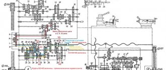
Kinematic scheme
For accuracy, we will divide the diagram into components.
Revolutions
The input shaft II of the gearbox receives torque from pulley 3, connected by a poly-V-belt to pulley 2 mounted on the end of the rotor of the electric motor M1. The spindle rotation side V is set by the engaged clutch of the double clutch 6.
When the left disks are compressed, forward revolutions are realized. The moment is transmitted through wheel 4 (5) to a double-crown block (8,9), then a three-crown block (13, 14, 15) is mated with one of the gears 10, 11, 12, a spindle double block (21, 22) with wheels 18, 19 respectively.
The search is activated by shifting the spindle unit to the right. The chain from shaft IV to V is closed by means of a block (23, 24) engaged with wheel 16 or 17, pair 25–27. Different positions of the blocks: (8, 9), (13, 14, 15), (21, 22) give 12 frequencies on the spindle, another 12 are obtained by enumeration.
When the right disks of clutch 6 are compressed, shafts II, III are connected through intermediate idler gears 28, 29, which reverse the direction of rotation. Further, the kinematics are identical to direct revolutions.
Rice. 4. Kinematics
Submissions
Each of the four possible movements of the caliper has its own kinematic branch: longitudinal, transverse feed, screw-cutting, high speed. Shaft VIII receives torque from the spindle through a transmission 20–32 or a step increasing unit (bringing), associated wheels 16, 33. From a reversing mechanism containing fixed wheels 30, 31; parasitic – 34, mobile – 35; through the guitar (a, b, c, d) the moment is transmitted to the receiving shaft X of the feed mechanism.
By switching clutches in different combinations with gear blocks, the speed of the final shaft of the XV feed box is changed. It transmits movement to the running shaft XVI or screw 61. The first option is obtained through two gear pairs mounted on bearings, an overrunning clutch 67, and fixed connected wheels 68, 64. In the second case, XV, 61 is connected by a clutch 60.
The rotation of the lead screw 61 is converted by a uterine nut mounted inside the apron into a linear movement of the carriage. By combining the switching of clutches and feedbox blocks, the required pitch is established. Part of the range is obtained by tuning the guitar by disconnecting the box with couplings 60, 116.
The shaft XVII of the apron mechanism receives movement from the running shaft with a sliding gear 65, along a chain 69 – 70 – 71, a coupling 72, a worm 73 connected to a wheel 74. By closing the cam coupling halves 77, 84, the direction of rotation of the XVIII with the wheel 94 is set. on a static rail 95, realizes the rectilinear movement of the carriage. Couplings 87, 90, connecting shaft XVII with screw 97, provide feed connection and reverse of the cross slide.
The rotation of the running shaft received from the motor 113 through the belt pair is converted into accelerated motion of the carriage. Thanks to the overrunning clutch 67, movement can occur with the box disconnected. Screws 97, 109 manually move the transverse, upper slide, rotating - 112, extend the quill.
Electrical equipment of the machine 16K25B
To ensure high reliability in operation and maintenance of the electrical equipment of the 16K25B machine by semi-skilled specialists, all relay-contactor equipment and other electrical equipment have a simple design and have been tested over many years of operation in various conditions.
The electrical equipment of the 16K25B machine (with the exception of several devices) is mounted in a control cabinet located on the rear side of the machine.
The electrical equipment of the 16K25B machine is designed for connection to a three-phase alternating current network with a solidly grounded or insulated neutral wire.
The electrical connection and the power cables used must comply with regulations. The voltage and frequency in the electrical network must correspond to the data on the machine nameplate. The fuse should be 25A.
Use connecting cables only with the designation H07RN-F.
Electrical connections and repairs must be carried out by qualified electricians.
The electrical connection is made to the terminal blocks in the electrical cabinet at the rear of the machine.
Safety instructions
The 16K25B machine must be securely connected to the workshop grounding device (circuit).
The electrical resistance measured between the ground screw and any metal part of the machine that may become live as a result of insulation breakdown should not exceed 0.1 ohm.
IT IS STRICTLY PROHIBITED to work with an open terminal box and control cabinet!
A safety light-signal device is installed in the control cabinet, indicating the presence of voltage between the output terminals of the input circuit breaker and the neutral wire.
Safety precautions
- Carry out work exclusively on screw-cutting machines for which you have access, and perform only the required work.
- Concentrate on work, without being interrupted by unnecessary things and conversations, and do not disturb other workers.
- Do not lean on a functioning lathe or allow others to do so.
- Do not give permission to your place to persons not related to the specific work. Do not trust the machine to another worker without the foreman’s approval.
- If you see another operator failing to comply with the rules, give him a warning about the obligation to comply with the provisions of the instructions.
- During repair work on the machine and starting mechanisms, it is necessary to hang a poster on it: “Do not start - repair.”
- It is prohibited to work on a lathe that is faulty and does not have the required guards, as well as to repair or remodel the machine yourself.
- Immediately inform the technician about any incident and go to the first aid station.
- To avoid accidents, contamination and chips getting into the devices of the screw-cutting machine, it is prohibited to blow air from a hose onto the surface being turned and the machine.
- It is forbidden to work on a lathe while wearing mittens and gloves, as well as with bandaged fingers without rubber fingertips.
- The dimensions and weight of the product being turned must meet the requirements of the lathe machine's technical passport.
- Firmly and rigidly fasten the workpiece being turned.
- If there is any interruption in the electrical power supply, immediately turn off the equipment.
- If there is voltage (feeling of current) on the metal parts of the screw-cutting machine, the electric motor operates in 2 phases (there is a hum), the ground wire is broken, stop the operation of the machine and immediately inform the foreman about the malfunction of the electrical equipment.
- Use a wooden grate and take proper care of it.
Locking devices for electrical equipment of machine 16K25B
The electrical circuit includes a lock that turns off the input circuit breaker when the control cabinet door is opened.
When the input circuit breaker is turned on, opening the cabinet door triggers the limit switch, which disconnects the electrical equipment of the machine from the network.
When the housing of the replacement gears is opened, a microswitch is activated, turning off the main drive motor.
The limit switch is mounted in the control cabinet, the microswitch is on the feed box housing.
For inspection and adjustment of electrical equipment under voltage (with the cabinet door open), the circuit provides a release switch installed in the control cabinet. This switch should only be used by qualified electricians.
Instructions for the initial start-up of the 16K25B machine
During the initial start-up of the 16K25B machine, it is necessary to check the reliability of grounding and the quality of installation of electrical equipment by external inspection. After inspection, disconnect the power wires of all electric motors at the terminal sets in the control cabinet and connect the machine to the workshop network using the input circuit breaker. Check the operation of all locking devices
- Using manual controls, check the precise operation of magnetic starters and relays.
- Once smooth operation of all electrical devices located in the control cabinet is achieved, connect the previously disconnected wires to the terminal sets.
- By alternately turning on the electric motors of the main drive and quickly moving the caliper, check the correct direction of their rotation.
- After making sure that the electric motors rotate correctly, you can begin testing the machine in operation.
Recommendations for servicing the electrical equipment of the 16K25B machine.
It is necessary to periodically check the condition of the starting and relay equipment of the 16K25B machine. All parts of electrical devices must be cleaned of dust and dirt. If carbon deposits form on the contacts, the latter must be removed using a velvet file or glass paper. To avoid rust, the interface between the core and the starter armature must be periodically lubricated with machine oil, followed by obligatory wiping with a dry cloth (to prevent the armature from sticking to the core). When inspecting relay equipment, special attention should be paid to the reliability of the closing and opening of contact bridges.
- The frequency of technical inspections of electric motors is set depending on production conditions, but not less than once every two months.
- During technical inspections, the condition of the input wires of the stator winding is checked, the motors are cleaned of contamination, and the reliability of grounding and connection of the shaft to the drive mechanism is monitored.
- The frequency of preventative repairs is set depending on production conditions, but at least once a year.
- During preventive maintenance, electric motors must be disassembled, internal and external surfaces must be cleaned, and bearing grease must be replaced.
- Under normal operating conditions, bearing grease should be replaced after 4000 hours of operation, and when operating the electric motor in dusty and humid environments - as necessary.
- Before filling with fresh grease, the bearings must be thoroughly washed with gasoline. Fill the chamber with lubricant to 2/3 of its volume. Recommended lubricants are given in table. 5.
- Preventive inspection of circuit breakers must be carried out at least once every six months, as well as after each shutdown due to a short circuit, including repeated ones.
- During inspection, you need to clean the switch from soot and metal deposits, check the tightness of the screws, the integrity of the springs and the condition of the contacts. The hinges of the switch mechanism should be periodically (after approximately 2,000-3,000 starts) lubricated with instrument oil.
ATTENTION! Do not make any adjustments to the switches under operating conditions. It was made by the manufacturer!