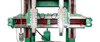
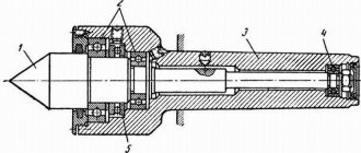
Using a lathe of one of the modern models, you can perform a fairly large list of technological operations for metal processing. But mainly such equipment is used to process the external and internal surfaces of workpieces having a cylindrical, conical and shaped configuration.
Modern lathe
History of the appearance and development of equipment
According to historians, lathes (or rather, the primitive ancestors of such devices) were invented and began to be used by man in the middle of the 7th century BC. Of course, such a device had a simple design, but it made it possible to effectively process wood or bone products. In order to carry out such processing, the part was clamped in two centers, which were mounted coaxially with each other. It was rotated manually, and the cutting process was carried out using a hand cutter, which was manipulated by a separate “operator”. Thus, the product was given the required shape and size.
The next stage of development that the equipment of the turning group underwent was equipping it with a drive necessary to impart rotational movement to the part. Initially, a bow string was used as such a drive, which was looped over the workpiece. And a little later (in the 14th century) a foot drive for turning equipment was invented.
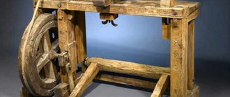
Antique foot operated lathe
The design of such a drive, very reminiscent of the drive mechanism of a foot sewing machine, consisted of a fixed cantilever wooden pole connected to the workpiece using a strong rope. When you pressed the pole with your foot, the rope was stretched, which led to the rotation of the workpiece by 1–2 turns. After the leg was removed from the pole, the rope was released and rushed upward, which entailed the rotation of the workpiece in the other direction.
Despite their simple design, such lathes already made it possible to perform processing with fairly high quality. Their advantage was that servicing the devices was very simple.
A. Nartov's turning and copying machine, 1729
The lathe of the 16th century group already had a steady rest and centers made of metal in its design, which made it possible to use it for processing workpieces with complex configurations. However, due to the low power of such a device, it was not yet possible to use it for turning metal workpieces.
The history of the lathe received a strong impetus in the 1700s, when the Russian Andrei Nartov created a device on which a mechanical support was installed. It should be noted that it was this innovation that served as the strongest impetus for the development of all equipment designed for processing metal workpieces. A major contribution to the development of turning units was made by French engineers, who by the middle of the 18th century created a device that was highly versatile. By the end of this century, French industry began to use a specialized unit on which it was possible to cut threads on metal screws.
Maudsley Lathes (click to enlarge)
The year 1794 is considered to be a truly breakthrough in the development of turning equipment, when Henry Maudsley created a machine that served as the basis for the further development of all turning units. What is noteworthy is that the company founded by Maudsley was also engaged in the production of dies and taps, with the help of which threads were cut on his equipment.
They began to think about automating a lathe in the 19th century, and American engineers took the lead in this matter. This process followed the path of equipping units with additional automation elements, which ultimately led to the creation of the first machine with a turret. It was on the basis of such devices that later they began to create universal automatic machines, the first of which (the Spencer machine) was presented to the public in 1973.
Airplane for weavers
When wefting by hand, the width of the fabric was limited by the reach of the weaver's arms, which had to reach from one edge of the fabric to the other. Wider fabrics were woven by two people - one weaver threaded the shuttle from the left, the other pulled it out from the right and threw it back. In 1733, the English clothier John Kay invented a shuttle-plane, pushed by races that were pulled by the weaver. The shuttle on rollers slid through the shed along the warp threads at the bottom of the shuttle shelf attached to the batan under the reed. The batan was tilted forward, the reed nailed the weft, and behind it the heddle replaced the warp threads. The shuttle was thrown back when the batan went back, opening the mouth in front of itself. Kay's shuttle speeded up the work and made it possible to weave wide fabrics alone.
The design of Kay's aircraft shuttle. With a rope (2) tied to the handle (1), the weaver pulled the race (3). The race pushed the shuttle (4), and it slid on rollers over the lower warp threads along the shuttle shelf (5) at the bottom of the baton (6), under the bird (7). The spring (8) pulled the race into place towards the edge of the shelf. The heddles swapped the warp threads, and the weaver pulled another race (9), pushing the shuttle back through the shed.
Classification of turning equipment
The classification of lathes, which was developed back in Soviet times, classifies such units into the first category of equipment intended for processing metal workpieces. According to this classification, all types of lathes are classified into one of the following categories:
- automatic and semi-automatic turning units with one spindle;
- multi-spindle machines: automatic and semi-automatic;
- revolver models;
- cutting group machines;
- carousel models;
- frontal and screw-cutting equipment;
- multi-cutting and polishing units;
- specialized machines, which can be conventional or automatic;
- special purpose devices.
Main types of turning work
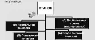
According to the degree of processing accuracy, the following types of lathes are produced:
- special accuracy - C;
- high accuracy - B;
- normal accuracy - N;
- especially high accuracy - A;
- increased accuracy - P.
Its functionality and, accordingly, its scope of application depend on the category to which the lathe belongs. You can also learn about the main technical capabilities of the machine by its marking, which includes the following:
- the initial number “1”, indicating that this is a lathe and not any other;
- a second digit indicating the type to which the turning unit belongs;
- the third digit (and in some models the fourth) is the most basic parameter of the machine, which characterizes the height of its centers.
Explanation of lathe markings (click to enlarge)
The marking of such units also contains letter designations that determine its design features: the level of its automation, accuracy, modification, and equipment with a CNC system. For example, the marking of the 1I611P lathe model is deciphered as follows: the letter “I” indicates that this is a screw-cutting lathe device; the letter “P” is a high-precision machine; The height of the centers for this model corresponds to 110 mm. You can guess what category of lathe you have in front of you by looking at the photo of the model.
Types of turning equipment
Turret lathes are designed for products that require processing of several surfaces using various tools. In order not to have to install and configure each tool, turret heads are installed on such machines, which can have two or more slots for placing tools. Of course, servicing such a lathe is much more difficult than a conventional model, but this is fully compensated by the functionality of this unit. For example, popular models of such machines are 1E316P, 1G340PTs, 1P371, 1A341.
A rotary lathe is one of the types of lathes
Rotary turning machines are designed for processing workpieces characterized by a short length, significant weight, and large outer diameter. These include dimensional gears, flywheels, etc. The functionality of such lathes (for example, models 1512, 1541, 1550, 1L532 and others) allows them to perform various types of turning work: turning, boring, cutting grooves, end processing, etc. And if you equip such turning units with additional devices, they will become even more versatile: with their help it will be possible to perform some milling operations, cut threads, grind and perform a number of other technological actions.
Working parts of a multi-spindle machine
Multi-spindle machines belonging to the turning group are necessary for performing complex technological operations in mass production conditions. Workpieces that can be processed on such machines can be in the form of pipes, hexagonal, square and round rods, shaped profiles, etc. This technique is distinguished by its high rigidity of design and powerful drive, which allows processing with high productivity.
What is important is that such complex and functional equipment is maintained in exactly the same way as a conventional machine. The list of technological operations that can be performed on such a unit is quite extensive: boring, roughing and shaping, cutting and rolling threads, etc. The most popular models of such turning equipment are 1P365 and 1B140 machines.
Screw-cutting lathe 16K20
Common models of turning machines, which gained wide popularity back in Soviet times, are screw-cutting lathes. Such machines, which can be found not only in almost any industrial enterprise, but also in school workshops, have gained their popularity due to the fact that with their help they can effectively perform a large list of technological operations.
Each such machine, regardless of the model, has a standard design consisting of the same type of components. Along with their functionality, screw-cutting lathe models are characterized by high safety, ease of operation and maintenance, which makes it possible to use them as units for equipping school workshops since the times of the USSR. The most famous and popular models of such turning equipment are machines 16K20, 16K50, 16B16A and 16P16P.
At enterprises that produce their products in large series and use blanks from shaped profiles and calibrated rods in production, automatic lathes are actively used. Such machines, which primarily perform turning operations in the longitudinal direction, cope with equal success in processing workpieces made of various metals: super-hard alloys, soft copper, etc.
On the domestic market, lathes are represented mainly by models from foreign manufacturers (Japan, South Korea, etc.). There are also some domestically produced models, for example 1M10DA.
Longitudinal turning machine 1M10DA
Operation[edit]
The weaving operation in a textile factory is carried out by a specially trained operator known as a weaver. Weavers are expected to adhere to high industry standards and will be tasked with supervising ten to thirty individual looms at a time. During a work shift, weavers will first use a wax pencil or crayon to sign their initials on the fabric to mark the change of shift, and then will walk along the weaving side (front) of the looms they are working on, gently touching the fabric as it comes in. from reed. This is done in order to feel for torn “picks” or filler threads. If broken cutters are found, the weaver will turn off the machine and try to correct the error, usually by replacing the bobbin with filling thread as soon as possible. They are taught that ideally no machine should stop for more than one minute, with faster turnaround times being preferable.
It requires more than 2 people to operate it due to the way it works.
Design features of lathe group machines
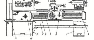
All machines designed for turning workpieces made of metal and other materials have standard structural elements in their design:
- bed - the supporting element of the turning unit on which all the elements of its structure are installed;
- apron (in this element of the lathe, the movement of the roller or lead screw is converted into the movement of its support);
- spindle headstock, on which the spindle of the device is located, and in its inner part there is a gearbox;
- caliper (in this element of the machine the cutting tool is fixed, the caliper is also needed in order to ensure longitudinal and transverse feed of the tool, carried out with the specified parameters; the design of the caliper must include a lower carriage, and some models have several of them, on the top of which a holder is attached for turning tools);
- feed box (using this structural element, movement is transmitted from the lead screw or roller to the machine support);
- the electrical part of the machine structure, which includes a drive electric motor, the power of which can vary significantly between different machine models, as well as elements that control the electrical equipment of the device (naturally, this part of the turning unit must meet safety requirements).
Main components of a lathe
All structural elements of the machine rest on two pedestals, which perform a load-bearing function and also ensure that the workpiece is placed at a height convenient for the operator. Such cabinets, distinguished by their massive design, can be seen in the photo of a lathe of any model.
The main part of the structural elements of turning equipment is unified, which makes it possible to quickly and cost-effectively carry out their maintenance and repair.
Lathe support design
Machine drive shafts
Example of lathe control layout (click to enlarge)
Dangers[edit]
When working with an experienced and careful weaver, the looms themselves are not dangerous. However, machines have a number of inherent hazards that can fall victim to inattentive or poorly trained weavers. The most obvious are the moving reeds, the frames that hold the fences, and the "pinch" or "sand" roller used to hold the fabric tightly as it passes over the front of the machine and onto the removable roller. The most common weaving injury is pinched fingers caused by distracted or bored workers, although this is not the only such injury found. There is ample evidence of weavers with long hair becoming entangled in the warp itself and tearing the scalp away from the skull or tearing off large chunks of hair. [12]As a result, it became an industry standard for companies to require weavers to either keep their hair up and tied, or keep their hair short to prevent it from getting tangled. Also, due to possible pinch points on the front of the machine, do not wear loose, baggy clothing. Additionally, the shuttle comes out of the loom at high speed (200+ mph/322 km/h) and strikes the worker when the moving tongue encounters thread/yarn or other mechanical snag/fault. From a safety perspective, one of the challenges for weavers is the loud nature of weaving mills (115 dB+). This makes it almost impossible to hear a person calling for help when they are confused, and this has led OSHA to formulate specific recommendations [13] for companies to reduce the likelihood of such circumstances occurring. However, even with such guidelines in place, injuries in textile manufacturing due to the machines themselves are still common.
