We will advise you on any questions!
Hot stamping, which involves deforming a metal workpiece in a heated state, is used to change not only the configuration of this workpiece, but also its dimensions. Most often, such a technological operation is used to change geometric parameters not in one plane, but in several dimensions. In such cases, this procedure is called “hot stamping”.
Hot stamping is usually used in mass production where a large amount of work is required
Hydraulic presses
Hydraulic presses are used to stamp large-sized forgings that cannot be produced on other forging equipment due to its insufficient power, and forgings that require a long working stroke for stamping (with deep piercing). Hydraulic stamping presses (Fig. 5) can create a force of 12.5. . .750 MN. The principle of their operation does not differ from the principle of operation of forging hydraulic presses, but stamping presses have a more rigid structure, are equipped with ejectors, mechanisms for installing and changing dies, etc.
Rice. 5. Large hot stamping press of the Nizhnekramatorsk Machine-Building Plant
Stamping as a popular industrial technology
More than 20% of the metal produced at enterprises in our country is stamped. It is quite difficult to find any technical mechanism or production machine that does not use stamped products. Parts produced using GS technology in modern aircraft, railway, and automobile technology account for 60 to 80% of the total weight of aircraft, locomotives, and vehicles. In addition, the described technique is indispensable for the production of a variety of household items, hardware, hardware, and all kinds of tools.
The basics of hot metal stamping technology were discovered by Vasily Pastukhov, a gunsmith from Tula. He made many weapon elements by stamping, using simple dies and a vertical screw press for these purposes. The technique developed by Pastukhov was introduced at the Tula plant in 1819. Nowadays, GS is a well-studied and “tested” process, which has almost completely replaced open forging operations.
The essence of technology
The essence of the hot stamping process is that the finished metal product is obtained from a workpiece heated to a certain temperature, applying pressure to it, for which a special stamp is used. When performing hot stamping, the temperature of the workpiece changes from the state of a simply heated surface to a forging one. To limit the flow of heated metal in an unnecessary direction, special cavities and protrusions are made in certain areas of the inner surface of the die. Thus, the inner surface of the stamp forms a closed cavity (stream), the configuration of which fully corresponds to the shape of the finished product.
Hot die forging (HSD) is performed on metal bars of various profiles - square, rectangular, round or periodic. In some cases, the production of finished products using hot stamping technology can be made from a solid metal rod. Initially, its part is formed into a forging with the required geometric parameters, and then it is separated by cutting. However, as a rule, blanks for hot stamping are cut from a metal rod.
Stamping of parts, which involves preheating them, demonstrates the greatest efficiency in serial and mass production. In particular, there are a number of advantages in using this technology for the production of metal products in large and mass batches.
- Waste of metal from which products are made is reduced.
- Labor productivity increases.
- Using this technology, it is possible to manufacture products of even very complex configurations.
- Finished products obtained by hot metal stamping are distinguished not only by their particularly precise geometric parameters, but also by their high surface quality.
Scheme of the technological process for manufacturing a part of the “connecting rod” type using the method of hot stamping.
The technological process of hot stamping includes a large list of operations performed from the moment the metal part is loaded into the processing zone and ending with the unloading of the finished product from the equipment. Designing such a process involves following the following algorithm:
- choose the method by which the product will be produced: on dies with an open or closed stream;
- develop a detailed drawing of the finished forging;
- establish how many transitions it takes to make a finished product;
- for each transition, develop a drawing of the forging being formed;
- depending on the required power for each stage of the technological process, select the appropriate equipment and form dies;
- Before hot stamping, heat the workpiece, choosing the heating method and modes of its implementation;
- depending on the requirements for the quality of the finished product, determine the list of finishing operations to which the forging will be subjected.
At the final stage of development of the technological process, it is necessary to calculate its economic and technical indicators.
Advantages and disadvantages of hot die forging
Metal processing performed by hot stamping can be carried out using various technologies, the implementation features of which depend on a number of parameters: the type of equipment used, geometric parameters and the material of manufacture of the product being formed. Using GOSH technology, the following types of parts can be manufactured.
Extended
Such products can be shafts for various purposes, connecting rods, levers and other parts of a similar design. A stamping press is used for their production. They are processed by flat hot stamping, while the original workpiece is subjected to a broaching operation. The final stage of production is shaping using the open forging method, carried out in the blanking rolls of forging rolls.
Disk
These are gears, flanges, hubs, covers and other parts of a round or square configuration, characterized by a relatively short length. To produce products of this type, they use upsetting technology, which is performed at the end of the workpiece being processed. To implement this technology, it is necessary to use stamping transitions.
Progressive methods of sheet metal stamping
There are several innovative cold stamping methods:
- Liquid treatment. With the help of high pressure and liquid, the metal is deformed. As a result, it takes the form of a matrix. This method is used for the manufacture of hollow, oblong parts.
- Explosion stamping. To change the shape of the metal, explosive gases (RDX, methane, propane) are used. The explosion creates high pressure. Because of this, the initial blank takes the shape of a previously prepared stamp. The pressure created by explosive gases makes it possible to produce parts of large sizes and complex shapes. The main advantage of such processing is the minimal cost of processing workpieces and eliminating the need to purchase expensive equipment.
- Rubber treatment. This method is used only for processing thin sheet metal (up to 2 mm).
- Electrohydraulic processing. The peculiarity of this method is that a high voltage electric charge is an energy carrier. The discharge passes through the liquid and causes a shock wave. Under the influence of pressure, the shape of the workpiece changes. The key advantages of this method are high accuracy and low energy consumption for the production process.
Every year new metal processing technologies appear that are more economical and more productive than the old ones.
Electrohydraulic processing
Stamping streams
When processing preheated steel products, as well as during hot stamping of brass, stamping strands are used, which can be:
- lingering (with their help, they increase the length of individual sections of the workpiece: frequent but gentle blows are applied to the part of the workpiece that needs to be lengthened, and at the same time the workpiece is tilted);
- blank (their goal is to shape the workpiece being processed: the metal is redistributed in its total volume in order to give the finished product a shape that ensures minimal waste of material);
- pinch (they are performed to reduce the height of a separate section of the workpiece while simultaneously increasing its width);
- rolling (streams in which the metal of the workpiece is evenly distributed along its axis, while the diameter of its individual sections increases);
- bending (in which the workpiece is supplied with a curved axis, a forging is formed, the bending angle of which is 90°).
The stamping strands in which the manufactured element acquires the required shape include:
- preliminary, or roughing, in which the shape of the workpiece being processed is as close as possible to the configuration of the forging (the features of such a groove, which may not be used when performing hot stamping, are that it has a slightly increased depth, also in it, compared to the parameters of finishing products, slopes and rounding radii have been increased);
- finishing, in which the part acquires its final shape, but its dimensions are increased by the amount of metal shrinkage when it cools (since in such streams it is necessary to exert maximum forces on the workpiece, they are located in the central part of the die).
Features of GCM
A horizontal forging machine (HFM) has dies consisting of a split engraving. The engraving has three parts: fixed, movable (clamping) and a punch with a connector in planes perpendicular to each other.
Metal reinforcement with a round or square cross-section is inserted into a stationary matrix, the movable matrix presses it, after which the punch deforms the workpiece, pressing it into the forming cavity.
After the deformation procedure, the dies are unclenched, the workpiece of the desired shape is pulled out, or it falls out on its own. The final result is achieved through several crossings in different streams. Due to the fact that the die has three working parts, the slopes and overlaps on the forgings are minimal or absent altogether. GCMs are characterized by low versatility and high cost.
Hot stamping has found its application in such industries as mechanical engineering, as well as in other industries that require the creation of complex parts made of steel, non-ferrous metals and their alloys.
Technological diagrams of stamping
Of the currently used hot stamping schemes, only two should be highlighted.
Closed stamping
This is a technological operation performed in a die, the gap between the moving and stationary parts of which is minimal. Hot stamping using this method can be performed on presses, when the upper part of the die is equipped with a protrusion, and the lower part is equipped with a cavity, or on hammers, when the cavity is in the upper part of the working tool, and the protruding part is in the lower part. The use of dies of this type requires that the volumes of the forging and the finished part exactly match. Closed-type stamps can have not one, but two parting planes located at right angles to each other.
Stamping in a single-strand closed die
Open stamping
Between the movable and stationary parts of the die for open hot stamping there is a special gap into which excess metal formed during its deformation is squeezed out. Open type dies, which is their great advantage, can be used for forgings of any type.
Stamping scheme in open dies
The use of closed type dies also has its advantages, which are as follows.
- Finished parts are distinguished by a more uniform internal structure and high quality external surface.
- Due to the absence of flash, metal consumption is reduced.
- It is possible to produce products from metals that are characterized by low ductility, since such processing is carried out under the influence of high stress and uneven all-round compression.
Hot stamping with hammers
Hammers belong to dynamic forging equipment (see Fig. 3.14). Their main disadvantages are the transmission of shocks during impacts to nearby equipment, to the structure of the forge shop building and surrounding buildings, a lot of noise and low accuracy of the resulting forgings. Despite these disadvantages, hammers are currently quite widely used in industry, since the dynamic impact on the workpiece is effective in cases of stamping forgings of complex shapes, as well as when processing difficult-to-deform and heat-resistant alloys.
For hot die forging, steam-air, mechanical and hydraulic hammers are currently used. The most widespread are steam-air hammers. Below we discuss in detail the processes of hot die forging on hammers, CGSP, GKM, as the most common in general mechanical engineering. Many factors of the technological process depend on the nature of the operation of the machine-tool, such as the heating method, the design of the tool (die), the number of stamping transitions, etc. Therefore, in the following paragraphs, the consideration of processes begins with a description of the device and operation of the corresponding equipment.
A double-action steam-air stamping hammer (Fig. 3.32) works on the same principle as a forging hammer, but has some design differences.
| . Rice. 3.32. Diagram of a steam-air stamping hammer: 1 – shobot; 2 — lower part of the stamp; 3 – upper part of the stamp; 4 – woman; 5 – stand; 6 – rod; 7 – piston; 8 – working cylinder; 9 – spool |
. If, during forging, products of a simple shape are obtained, then during stamping they strive to achieve maximum approximation of the shape of the forging to the shape of the finished product, and the forgings turn out to be quite complex - with ribs, protrusions, cavities, etc. Therefore, it is necessary that the blow be as hard as possible, i.e. i.e. the maximum share of the impact energy would be spent only on the deformation of the forging. This is ensured by the high rigidity of the falling parts and the large mass of the chabot. The mass of the die of a stamping hammer is 20 times greater than the mass of its falling parts. The alignment of the axes of the upper and lower parts of the stamp during stamping is ensured by the presence of elongated adjustable guides and by fastening the hammer posts directly to the chabot. During the stamping process, the blacksmith himself controls the hammer by pressing a pedal or handle. Steam-air stamping hammers are manufactured in accordance with GOST 7024-75 in eight standard sizes with a mass of falling parts from 630 kg to 25 tons .
For stamping, steam-air hammers with double-sided impact
(Fig. 3.33).
These hammers do not have a chabot, and the women move towards each other. As a result, the impact energy is almost entirely spent on the deformation of the forging and is mutually absorbed by the women, without being transferred to the foundation.
| Rice. 3.33 Diagram of a steam-air hammer without a hammer with a hydraulic connection of the heads: 1 upper head; 2, 5 – shock absorbers; 3 – plunger; 4 – lower woman; 6 – rod; 7, 8 – plungers; 9 - compensators; 10 – lower cross member |
The top woman 1 is the leader. Moving down under the action of steam pressure or compressed air, it sets the lower head 4 in motion through a mechanical or hydraulic connection. With a hydraulic connection, the lower wheel 4 is accelerated by the force of fluid pressure in the lower cylinder. When the upper woman 1 moves down, the rods 3 press on the plungers 7, pushing them down. As a result, the liquid (mineral oil), located in a closed volume, is forced out from the side cavities of the lower cross member body 10 into the middle one and moves the plunger 8 upward, and through the rod 6 and the lower head 4 upward until it hits. By the time of impact, the lower woman develops the same speed as the upper one. At the junction of the rods and the heads there are shock absorbers 2, 5, and hydraulic shocks in the liquid are softened by compensators 9. Hammers of this design are highly reliable and are manufactured with an impact energy of up to 1,400,000 J, which is equivalent to a steam-air hammer with a mass of falling parts of 70,000 kg. The main disadvantage of hammerless hammers is the impossibility of stamping in multi-strand dies, since it is difficult to move the workpiece from one strand to another. The best results are obtained when stamping heavy blanks of axisymmetric parts - gears, flanges , bushings, etc. in single-strand dies.
Mechanical hammers cannot develop high impact energy, which is why they are gradually falling out of use, and hydraulic hammers have not yet found widespread use.
Hydraulic forging presses. See page 56 - repeat The action of a hydraulic press is based on Pascal's law, according to which the pressure exerted on a liquid is transmitted equally in all directions. The schematic diagram of any hydraulic press is shown in Fig. 3.34. If two communicating cylinders are filled with liquid and two plungers (pistons) are immersed in it, one of which has an area F
1
,
and the other
F
2
,
then with a small force
P
1 acting on the plunger
3 of the pump with an area F
1
,
it is possible to create a large force
P
2,
with
which the plunger
1 of the working cylinder of the press with an area F2
will deform the workpiece
2 .
Pump plunger
3 exerts pressure p = P
1
/ F
1
.
This pressure is directed to the base of the plunger
1 and creates a force P
2
= pF
2
.
The force
P
2 will be as many times greater than the force
P
1, how many times the area
F 2
is greater than the area
F
1, i.e.
P
2
= P
1
F
2
/ F
1
.
The diagram of a hydraulic forging press with an individual pump batteryless drive is shown in Fig. 3.35. The working force of the press is created by a liquid (water emulsion or mineral oil) supplied under high pressure (20-30 MPa) to the working cylinder 1 from the pump 6 through the control system 5 . The liquid presses on plunger 2 , which transmits force to the movable cross member 7 . The latter moves along 4 ,
rigidly connected by upper and lower fixed crossbars
3 and 9 .
When the cross member
7 the liquid from the return cylinders 10 is displaced by the plunger 11 .
The workpiece is deformed by strikers
8,
which are attached to the fixed
9
and movable 7 crossbars.
To lift the cross member 7 after completing the working stroke, liquid under pressure is supplied to the return cylinders 10 , and is forced 1 2. Thus, the cross member makes a forward and reverse stroke. The direct stroke has two sections: the approach stroke, during which the working tool is brought to the workpiece, and the working stroke, during which the workpiece is directly deformed. Stopping the movable cross member to perform auxiliary operations (changing tools, moving a workpiece, etc.) is called a technological pause. The design of hydraulic presses is very diverse and is determined by their technological purpose and the force developed.
An open hammer die for single-strand stamping (Fig. 3.36) consists of a lower 5 and upper halves 7 , which experience dynamic loads during operation. To avoid rapid destruction, each half is made in the form of a monolithic cube made of expensive chromium-nickel steel. For fastening to the hammer, both halves of the die have “dovetails”, with the help of which they are pushed into the grooves on the head and under the die pad (die holder) of the hammer and secured with keys 10 and 12 and wedges 4 and 8 .
The keys serve to prevent relative shifting of the die halves. They are installed in the milled recesses of the shanks of the woman and the stamp holder. The latter serves to protect the chabot 1 from wear and is secured to it with a wedge 2 .
The dimensions of shanks, wedges, keys must comply with GOST 6039-71.
To move (transport) holes 6 and 11 .
In each of the die halves, recesses corresponding to the shape of the forging are made, forming a stamp stream, around which a flash groove is located. The plane along which the halves of the stamp touch is called the parting surface,
and the line passing along the outer contour of the forging in the parting plane is
the parting line.
Rice. 3. 36 Hammer stamp and its attachment to the hammer: 1 – chabot; 2,4,8 - wedge; 3 – plate; 5- lower stamp; 6.11 – cargo holes; 10.12 - keys
Depending on the shape of the forging, the parting surface can be a whole plane or consist of several planes; in the latter case, its projection onto the vertical plane is a broken line.
The number of die grooves depends on the shape of the forging. The more complex the forging, the more streams there are. A change in the shape of a workpiece in one strand is called a stamping transition (Fig. 3.37, c
)
.
After each transition, the shape of the workpiece approaches the shape of the forging. Therefore, the more complex the forging shape, the more grooves the die should have.
According to the purpose of the streams (Fig. 3.37, d
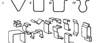
) are divided into blank and stamping. When stamping from rolled stock, a redistribution of the volume of metal occurs in the blank strands in order to bring the shape of the workpiece closer to the shape of the forging. Depending on the nature of the redistribution of metal volumes, procurement streams can be drawn-out - for drawing (lengthening) the workpiece; pinch - designed for local enlargement of the workpiece and slight redistribution of metal along the axis. The workpiece is processed in one or two strokes without turning and is transferred to the roughing or finishing stamping groove without changing position; rolling - designed to locally increase the cross-sectional area of the workpiece by reducing the cross-sectional area of adjacent sections. Rolling is performed in several blows with the workpiece being turned around the longitudinal axis by 90° after each blow; bending - used for bending the workpiece along the axis in accordance with the shape of the forging in plan; molding - to give the workpiece a shape close to the shape of a forging. The type of blanking strands is chosen depending on the shape of the forging. When stamping forgings by upsetting at the end, the blank stream is called the upsetting platform.
Rice. 3. 37 Multi-strand hammer die for stamping a connecting rod flat: a - forging of a connecting rod after trimming the flash; b - stamp; c — stamping transitions: 1 — stretch; 2 — rolling; 3 — stamping in a preliminary stream; 4 — stamping in the final stream; g - stamp streams; 1 - lingering; 2 - rolling; 3 — preliminary (draft); 4 - final
The final design of the forging takes place in the stamping streams. Stamping streams are preliminary (black) and final. Preliminary (rough) grooves are used when stamping forgings of complex shapes in order to avoid rapid wear of the final (finishing) groove. In the preliminary flow, the workpiece takes the form of a forging with slightly increased dimensions due to the absence of flash. It is located next to the finishing groove, does not have a flash groove and is designed to bring the shape of the workpiece as close as possible to the shape of the forging in order to increase the durability of the finishing groove, improve its filling and reduce metal consumption. The workpiece from the rough stream is laid loosely in the finishing stream.
After stamping in the final strand, the forging acquires the given shape and dimensions and has a flash (Fig. 3.37, c
).The groove for the flash is located in the plane of the die connector along the perimeter of the stream. The final stamping groove must be located in the center of the stamp or with as little offset from it as possible. Harvesting streams are located along the edges of the die and can be open or closed.
If several forgings are stamped from one workpiece, then a cutting stream is provided at one of the corners of the die to separate the stamped forging from the rod.
The position of the die parting plane must ensure free removal of the forging from the grooves. For this purpose, streams should have the smallest depth and greatest width. The parting surface must be flat and intersect the vertical surfaces of the forging so that the movement of one half of the die relative to the other can be easily detected. If the forging is asymmetrical, then deep cavities, bosses, and ribs should be located in the upper part of the die, since the metal flows upward better.
To facilitate the removal of the forging from the die, all vertical walls of the streams are made with slopes called stamping slopes. The angle of inclination to the vertical on the outer surfaces of hammer forgings is 7°, and on the inner surfaces - 10°. In addition, both in dies and on forgings, radii of curvature are provided at the corners of intersections of surfaces, which prevents clamping of the forging metal in the corners of the die and destruction of the latter due to stress concentration.
Let's consider a multi-strand hammer die with a wider range of strands: finishing strand
(Fig. 3.38,
a
);
black stream
(Fig. 3.38,
b
), which is located next to the finishing stream;
procurement streams: long open and closed streams
(Fig. 3.38,
c, d)
are designed to increase the length of the workpiece or its individual sections by reducing the cross-sectional area. Broaching is performed in several strokes with the workpiece being bent after each stroke.
Rolling open and closed streams
(Fig. 3.38,
d, f
)
Pinch Stream
(Fig. 3.38,
g
)
The forming groove
(Fig. 3.38, h) is designed to give the workpiece a shape corresponding to the shape of the forging in the parting plane. Forming is performed in one or two strokes without turning the workpiece. Then the workpiece is transferred directly into the finishing stream with edging around the axis at 90°.
bending stream
(Fig. 3.38,
i
)
The platform for upsetting
(Fig. 3.38,
j
) is designed for upsetting workpieces at the end to the required height and diameter. It is usually located in the front left corner of the die, closer to the heating furnace. Upsetting is carried out in one or several blows and is used to produce forgings that have a circular shape in plan or close to it. Sometimes, for better centering of the workpiece in the stamping groove of the die, the upsetting is combined with extrusion or partial piercing of the workpiece.
Bran stream - knife (Fig. 3.38, l
) is used to separate the forging from the rod and is placed in one of the corners of the die.
To accommodate the castor bean (the end of the workpiece), captured by the pincers, a recess is made in the die, connecting to one or another stream. The required number and combination of grooves in the die are determined primarily by the shape of the forging: the more complex it is and the more it differs from the shape of the workpiece, the greater the number of grooves in the die is required for its manufacture. Distance between
streams are chosen taking into account the stamp.
The stamps are installed on the hammer, combining two mutually perpendicular planes planed on the front and side edges of both halves of the stamp, forming a control angle (see Fig. 3.36). Hammer dies, due to the impact nature of the hammer’s operation, are made as solid blocks and, less often, with grooved inserts.
Stamping with hammers in closed dies is also promising. Compared to stamping in open dies, it allows you to save metal by eliminating waste from burr and castor beans, perform stamping on hammers with a smaller mass of falling parts, and eliminate the operation of trimming burr from the technological cycle.
The durability of the die depends on the mass of the falling parts of the hammer on which the die is installed, and is determined by the number of forgings obtained on the die within the tolerances between its two repairs.
The volume of the workpiece Vzag during stamping on a hammer represents the sum of the forging volumes Vpok of the volumes of technological waste. The type of technological waste depends on the stamping method (flat or upsetting). When stamping flat, technological waste is formed from flash V
about, castor bean
V
cl, and waste
V
ug Castor bean is the part of the workpiece intended for capture by mite sponges.
Thus, V zag = V pok + V rev + V cl + V kg,
When stamping by upsetting the castor bean is absent in most cases. When stamping forgings for ring parts with a hammer, a through hole cannot be obtained. In order to save metal and to facilitate subsequent piercing, indentations (marks) are made in forgings on both sides. Between the protrusions of the die, which form recesses (marks), a film remains in the forging, the volume of which V is included in the waste.
In any case, process waste should be as minimal as possible.
Before hammer stamping, various heating methods are used. For forgings with correspondingly favorable dimensions, non-oxidizing contact heating is used. The use of flame heating in methodical and semi-methodical furnaces (automotive industry) is also economically justified. In this case, the scale layer is approximately 2% of the forging volume. Due to the dynamic impact of the hammer on the workpiece, the scale is separated from the workpiece during the first blows and removed from the die parting plane by compressed air, which prevents its negative impact on the surface of the die and stamping into the forging. Expensive induction heating during hammer stamping is not economically justified.
Stamping on hammers produces forgings of a wide variety of shapes, mainly in open dies, from a wide variety of metals and alloys.
Features of hammers and crank presses
Some stamping shops now use steam-air hammers that can operate on both air and steam. This equipment is considered obsolete. To produce a stamped part using hammers, it is necessary to install bulky equipment, to fix which a very complex and deep foundation is built. Moreover, such a unit must be installed in a fairly high industrial building.
Steam-air hammer in a stamping shop
The efficiency of working with hammers is at the level of 2–3%. It turns out that during stamping a large amount of coal is burned, and the return from the process is minimal. In addition, only experienced and physically strong specialists can operate hammers. At the same time, even they are forced to make a lot of effort to ensure that the finished products meet the requirements set out in the technical specifications for the production of stamped parts. The advantages of stamping with hammers include the fact that they make it possible to produce forgings of almost any configuration at a fairly high speed.
GKShP - crank presses - have become a good replacement for bulky hammers.
Crank press for metal stamping
They operate not by impact (as happens when performing work operations on hammers), but by pressure. Such units are equipped with an electric motor, which drives the hydraulic thruster through a system of shafts, flywheels, connecting rods, gears and couplings. Crank installations stamp products in one operation, which increases their productivity by 1.5–2 times compared to the production of parts using hammers.
Other advantages of GKSHP include:
- minimum tolerances and allowances on the resulting products (no additional mechanical processing of stamped products is required);
- sufficiently high efficiency of their operation;
- safety of work operations.
Advantages and disadvantages of the process
Hot stamping has some advantages and disadvantages relative to forging.
Advantages of GOSH:
- high productivity exceeds forging hundreds of times;
- production of finished products of complex configuration;
- relative simplicity of a specialist’s work and faster training in the necessary skills;
- fewer tolerances and allowances, since only the contacting surfaces of the parts are machined, and the remaining surfaces have satisfactory geometric parameters and roughness. After calibration, tolerances are only 0.05 mm.
The disadvantages are:
- the weight of the finished product does not exceed 3.5 tons;
- the high cost of a special die tool in contrast to a forging tool. The die is made on the basis of high-quality steel and is used exclusively for a certain size of forging;
- the need to use more powerful equipment due to the deformation of the entire workpiece, and not part of it, which requires an increase in the impact force. And also the walls of the die cavity experience pressure during the flow of metal, which affects its wear resistance.
Horizontal forging machines.
These machines perform hot heading of various parts (such as a rod with a thickening, a through hole, a blind cavity, a complex configuration, etc.) from rod material or pipes in multi-strand dies. The design of the dies also allows for punching holes, cutting along a contour, cutting off a rod, etc. Horizontal forging machines are distinguished with dies being separated in the vertical and horizontal planes.
The general view and kinematic diagram of a horizontal forging machine with a vertical matrix split are shown in Fig. 48, a, b. Electric motor 1, through a V-belt drive 2, a flywheel 3 and a clutch 4, rotates the drive shaft 17. This shaft transmits rotation to the crankshaft 22 through the small 16 and large 21 gears. The crankshaft covers the connecting rod 20, which sets the main slider 19 in reciprocating motion. An eccentric 23 is mounted on the crankshaft, driving the side slider 5. The latter, moving forward, moves the system of levers 6, 7 and 8 associated with the clamping slider 9 .
Thus, rotation of the crankshaft causes translational movement of the side 5 and clamping 9 sliders; Almost simultaneously with them, the working movement (forward movement) of the landing or main slider 19 occurs.
The front stop 13 is connected to the upsetting slide through a system of levers and rollers. In the initial position of the slides 19 and 5 (this position is shown in the figure), the stop 13 is lowered into the stamping space and is located between the punch 14 and the halves 11 and 12 of the matrix. The heated workpiece fed forward comes into contact with the stop. As soon as the sliders begin to move forward (working stroke), the stop 13, using the lever 15, begins to rise and leaves the die space. The clamping slider 9, leading the upsetting slider 19, clamps the workpiece between the halves 11 and 12 of the matrix, after which the upsetting slider hits the end of the workpiece with a punch 14.
After landing, the sliders move back, the forging is released and the stamper removes it or transfers it to another stream.
The horizontal forging machine has idle and working strokes. Idling begins when the electric motor is turned on, when only pulley 3 rotates, but clutch 4 is turned off; brake 18, located on the right side of the drive shaft 17, keeps the drive shaft from rotating. When pedal 10 is pressed, compressed air enters the clutch and turns it on, which loosens the tightened brake bands and causes the drive shaft to rotate. At the same time, the air entering the brake 18 releases the tightened brake bands, and rotation from the drive shaft is transmitted to the crankshaft.
The productivity of horizontal forging machines is high (400-900 forgings per hour).
At domestic factories, horizontal forging machines are manufactured with a force of 1-31.5 MN (100-3150 tons) with a number of strokes of 95-21 per minute.
For stamping on horizontal forging machines, blanks with a diameter of 20-270 mm and a weight of up to 100 kg are used.
Date added: 2014-02-05; 6565; Does the published material violate copyright? | Personal data protection |
Didn't find what you were looking for? Use the search:
Horizontal forging units – a guarantee of efficient stamping
The most productive and economically feasible units for use are horizontal forging machines (HFOs). They are used in the production of all kinds of parts that require transitions from one technological operation to another (piercing, upsetting, separation of part of a workpiece rod, extrusion, pinching).
Manufacturing of parts at GCM ensures:
- excellent product quality;
- unique performance and efficiency of GS;
- high precision of the resulting forgings;
- absence of defects (burrs and others) on the parts.
GCMs can have two options for the matrices parting plane – horizontal and vertical. The main characteristic of such units is the amount of force (nominal) on the machine slide. Without exception, all parameters of modern domestic gas and condensate compressors are established by Gosstandart 7023–90.
A standard horizontal forging unit operates according to the following scheme:
- a movable type matrix is attached to the GKM frame, to which the workpiece is pressed;
- the movement of the installation slide begins and the metal is punched out (the grooves of the stamp are filled according to the configuration of the product that needs to be obtained as a result of the stamping operation).
Standard horizontal forging unit
The GCM usually produces parts that have thickenings of certain sizes in the middle or at the ends. Also, these machines produce a wide range of products that are separated from the original workpiece using hole-piercing technology. These include flanges, nuts, and rings.
Stamping of forgings on GCM is characterized by technological operations that differ from the GSH procedure on presses and hammers. Hammered products have higher allowances for machining than parts produced on forging units. In addition, forgings from horizontal installations require less metal waste; they do not have flash or stamping slopes. The latter are always present when stamping with hammers. For mass and large-scale production of products of the same type, for the reasons stated above, GCM should always be used.
Tools and equipment
Stamping production using cold and hot methods requires a number of tools and devices. The equipment used for stamping is conventionally divided into main and auxiliary.
The first group of tools includes dies, which in turn are divided into forging dies for making products and trimming dies for eliminating burrs after stamping.
All of them are intended to create exclusively a given part, but sometimes you can also find options with removable parts and blocks that allow reconfiguration.
Stamping tools for hot technology are made from high-quality alloy tool steel, because the products are subject to high mechanical pressure and thermal load during operation.
But this is a rather expensive material, so to save money, stamps are made with inserts made of cheaper metals.
Cold metal stamping involves the use of equipment that operates under high specific loads and ensures high accuracy of product shapes and sizes. It is characterized by high productivity and increased stroke, as it has high structural rigidity.
The process of obtaining volumetric stamps.
The second group of tools and devices for stamping includes:
- devices that allow the delivery and loading of metal into the furnace, its supply from the furnace to the hammer and the transfer of blanks from one hammer to the next;
- equipment for feeding blanks under the stamping press with their subsequent transfer from one die strand to another;
- tools for removing forgings from dies after production;
- measuring instruments and templates for periodic inspection of stamped forgings.
On a note! The design of the stamp must have such operational parameters that it allows changing the shape of the workpiece according to specific requirements, is firmly fixed on the equipment, and provides the opportunity to maintain the accuracy of its installation and comfortable transportation.
To process metal parts using hot stamping, you will need the following equipment:
- hammer dies;
- hot stamping crank presses;
- horizontal forging units.
The most common options today are double-action steam-air hammers and simple friction driven hammers. They work due to the shock-deforming effect on the metal workpiece.
High-quality redistribution of metal can be ensured by simultaneous regulation of the stroke of moving parts and impact force in combination with tilting the workpiece. Note that hammers are classified as fairly inexpensive stamping equipment.
Also, when hot stamping, crank presses with a rigid drive are often used, which does not allow changing the direction of the slide.
Forgings made using presses are distinguished by greater accuracy due to their rigid motion. This reduces the risk of machining allowances to a minimum.
The disadvantage of such equipment is the need to pre-clean the workpiece from scale, otherwise it will be pressed into the body of the forging.
When the heated metal comes into contact with the walls of the press, the workpiece cools down due to the large amount of time spent on the deformation process.
Subtleties of stamp making
Special strand molds for stamping are operated at elevated stresses and high temperatures. Naturally, this causes their rapid wear due to a decrease in the initial durability, which is understood as the number of forgings produced by the die before it fails. The level of mold resistance for a GS depends on the grade of steel used to make the die, the quality of its finishing and design, and the complexity of the grooves.
The raw materials for the production of dies are usually high-alloy steels (5ХНТ, 5ХНВ). Molds made from them do not wear out for a long time, as they have high strength and undergo special mechanical processing on milling, planing and lathes.
Dies are made according to a rather complex scheme, which includes performing a number of labor-intensive operations:
- castings or forgings – preparation of the workpiece;
- processing on metal-cutting equipment - increasing strength characteristics;
- hardening (heat treatment at a certain temperature) and tempering;
- fine-tuning
Dies for working on GKM and GKShP, as well as on hammers, are made of two parts, each of which has streams. When they come into contact, they form a cavity identical to the shape of the part being manufactured. The lower part of the stamp is mounted in a stationary press mechanism or in a special holder, the upper part is installed in the headstock of the stamping unit.
Stamp for working on GKM and GKShP
Complex products are produced in multi-strand forms. If the streams in them are made deep, it is necessary to treat them with fuel oil, which, when evaporated during the stamping operation, forms a gas mixture. It expands and makes the procedure for removing the finished product from the stream much easier and faster.
Billets for HS are heated in different types of furnaces - gas, coal, electric and oil. At the same time, they always strive to ensure that oxidation does not occur on the surface of the molds (scale does not appear). At some modern enterprises, stamping blanks are heated in high-frequency units. Such installations eliminate the possibility of overburning products, allow for complete automation of the heating operation and prevent the development of oxidative processes.