The cast stator, which forms the basis of the compressor, has an internal non-circular cylindrical surface, the contour of the base of which is calculated using a special program and has a complex geometry. This geometry allows you to optimize the pattern of movement of the plates when the rotor rotates, providing a long arc of the compression zone without distinguishing the suction and discharge zones. The cast stator forms the crankcase. The rotor, as well as its shaft, made of spherical graphite, is mounted in two roller bearings. Its location is very important for the efficiency of the compressor, so the optimal option would be one in which the gap between the rotor and stator along the forming surfaces in the area separating the compression cavity from the suction cavity is minimal.
The vanes, of which there are up to eight in this type of compressor, are made of carbon fiber bonded with an aromatic linear polymer and impregnated with polytetrafluoroethylene (PTFE or Teflon). This special treatment ensures self-lubrication in the event of a malfunction in the oil circuit. The material of the plates is very durable and can withstand high temperatures of about 180°C. At the exit of the compressor shaft from the crankcase, a classic seal is provided, consisting of a steel race, a ceramic liner and a metal bellows.
Thanks to the use of an additional circuit with a heat exchanger, the vane compressor can operate at evaporation temperatures down to −40°C. In this case, high-pressure liquid is used to feed the intermediate heat exchanger: the liquid in the main circuit is supercooled before throttling, while the gas expanded in the secondary circuit is injected into the compressor through an opening located in the compression zone. As a result of installing an additional heat exchanger, a double effect is achieved: the cooling capacity increases by approximately 20-30% with an increase in power consumption of only 8%, i.e., the refrigeration coefficient increases, and, on the other hand, the discharge temperature drops.
As for the possibility of changing the cooling capacity, this type of compressor does not provide any internal devices. Considering the low cost of such compressors and some other advantages, they are usually used only in installations where the load varies very little. If, however, there is a desire to change their cooling capacity, then it is necessary to change the compressor speed using either a multi-speed motor or a frequency converter, which can provide a continuous change in rotation speed in the range from 400 to 4000 rpm.
Vane compressors also have water hammer protection devices. Thanks to the presence of a squeezable plate with return springs, in the event of hydraulic failure, the compression cavities can be opened, as a result of which the compressor can operate continuously, even if liquid enters the suction line.
Volumetric compressors with rotational movement of the working body that compresses gas are called rotary. The most common design types of rotary compressors are: rotary vane; rotary vane with a rolling piston; liquid-ring.
Rotary vane compressors (Fig. 2.31) are available with steel plates and relief rings that reduce plate wear, as well as with plates made of non-lubricated anti-friction materials. When operating vane compressors, it is necessary to install a discharge or check valve.
Modern liquid ring compressors (Fig. 2.32) and vacuum units are supplied fully equipped in a monoblock design without a foundation, with a unit capacity of 150–400 m/min, and a discharge pressure of 0.15–0.25 MPa.
Advantages of liquid ring compressors: simplicity of design and operation, practically isothermal compression process, the ability to pump out and compress toxic, explosive, easily decomposing, polymerizing and flammable gases, vapors and liquid-gas mixtures, including aggressive ones and contaminated with mechanical impurities.
Rice. 2.31. Rotary vane compressor: 1 – housing; 2 – rotor; 3 – plate;
4 – shirt; 5.6 – suction and discharge pipes
Rice. 2.32. Liquid ring compressor: 1 – wheel; 2 – body;
3 – suction window; 4 – discharge window; 5 – liquid
The Roots type compressor (Fig. 2.33) is a valveless positive displacement machine with two rotors, two or three blades. Two identical rotors (usually symmetrical) rotate in opposite directions inside a housing made up of two cylinders. The gaps between the rotating rotors (0.1–0.2 mm) are set using synchronizing gears located outside the housing.
Rice. 2.33. Roots type gas blower
Compression occurs by the reverse flow of gas from the injection area at the moment when the rotor blade connects the cut-off portion of gas with the injection area.
The widespread use of Roots-type compressors in a number of industries is explained by the simplicity of their design and operation, the absence of rubbing elements and lubrication in the flow part, balance, and durability.
Roots type compressors are produced with a capacity from several liters per minute to 2000 m/min with a discharge pressure of up to 0.15 MPa.
For a full revolution, four portions of gas are theoretically transferred into the discharge cavity in a two-blade rotor, and six portions in a three-blade rotor.
Theoretical performance of a compressor with two-blade rotors
,
,
where L
– rotor length;
F
– rotor cross-sectional area.
When introducing k
– coefficient taking into account the useful use of area:
,
Actual compressor capacity
where k =
0.53–59 – for two-blade,
k =
0.49–0.53 – for three-blade compressors.
,
where is the productivity coefficient (=0.65–0.85).
In order to reduce vibroacoustic activity, the peripheral speed of the compressor rotor should not exceed 40 m/s. Ratio of length to radius of the cylinder = 1.6 – 3.0.
Compressor shaft power
,
=0.87–0.94 – takes into account friction losses in bearings, the end parts of the rotor on the cover, in gears, etc.
The design of the screw compressor was patented in 1934. Reliability in operation, low specific metal consumption and overall dimensions predetermined their wide distribution. Screw compressors compete with other types of positive displacement compressor machines. The absence of valves and unbalanced mechanical forces allows screw compressors to operate at high speeds, i.e. obtain greater productivity with relatively small external dimensions.
The working parts of screw compressors are rotors (1–3) with screw teeth cut on them. The most widespread are two-rotor machines. The rotors rotate in a housing that performs the functions
cylinder (Fig. 2.34).
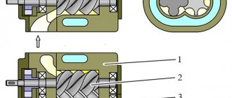
Rice. 2.34. Screw compressor: 1 – driven shaft; 2 – drive shaft;
3 – synchronization gears; 4 – body; 5 – support bearings;
6 – thrust bearings; 7 – seal unit
The rotors of modern screw compressors are helical gears with a small number of teeth of a special profile. Each pair of teeth forms a screw channel filled with gas. The drive rotor has convex wide teeth and is connected to the motor. The driven rotor has concave and thin teeth.
Screws of constant cross-section are placed in cylindrical bores of the body. The borings intersect with each other, forming a figure-eight cross-section. These cavities are connected diagonally to the suction and discharge chambers through special suction and discharge cavities (windows). The suction window has the shape of an annular sector and is located at the end of the screws, the discharge window is located on the side or at the end of the screws. In the region of gas compression, the peripheral velocities of the screws are directed towards each other and the teeth of the screws converge. On the opposite side, under the screws, the peripheral velocities are directed away from each other and the teeth of the screws diverge, due to which gas is suctioned (suction area).
Read also: What power is needed for an ice drill?
The operating principle of a screw compressor is as follows. From the suction pipe through the window, gas enters the space between the teeth, called depressions or cavities, which, when the screws rotate, are gradually filled with gas, starting from the suction end. After turning the screw at a certain angle, the steam cavity, having passed the suction window, is disconnected from the suction window.
This completes the absorption process. The volumes of gas that filled the cavities of the driving and driven screws, isolated from each other and limited by the surfaces of the rotors and the housing, are disconnected from the suction chamber, but are not yet connected to the discharge chamber. When rotating the screws, gas ,
filling the depressions, moves to a certain angle, and then its compression begins. As the tooth of the driven screw enters the cavity of the driving screw, the volume occupied by the gas decreases and the gas is compressed.
The process of gas compression in the cavity (called the steam room) continues until the ever-decreasing isolated volume of the steam cavity with compressed gas approaches the edge of the injection window. At this moment, the internal compression process in the compressor ends. Thus, the internal gas compression in the compressor for these screws depends on the location of the discharge window. With further rotation of the screws, after connecting the cavity with compressed gas to the injection chamber, the process of pushing out the gas occurs.
The internal gas compression pressure may not coincide with the discharge pressure, i.e. the pressure of the gas supplied to the consumer: if it is less than the discharge pressure, then the gas is externally pressurized to the discharge pressure; if it is higher, then there is a slight drop in the pressure of the compressed gas.
The magnitude of the internal compression pressure in a screw compressor depends on the size of the discharge window. The paired cavities formed between the screws must be isolated from the same cavities located in front or after them, and those, in turn, from neighboring ones. This is achieved by selecting the appropriate screw tooth profile. Practically, due to the inevitable gaps between the teeth (even with a theoretically hermetically sealed engagement) and the gaps between the screws and the body along the cylindrical surfaces and at the ends, there is a connection of adjacent paired cavities. The size of these gaps is kept as small as possible.
The processes of suction, compression and expulsion of gas in a screw compressor alternate for each individual pair cavity. But thanks to the continuous following of the cavities one after another at high speed, an almost continuous supply of gas is ensured.
Screw compressors are divided into two groups: dry and wet compression machines (oil-filled). Dry compression screw compressors supply dry gas ,
oil-free. The screws rotate in the housing without contact with the housing and with each other, which is ensured by the presence of synchronization gears. Oil injection into the working space makes it possible to obtain a pressure increase of up to I5–20 in a single-stage machine versus 4–5 in a dry compression compressor.
The clearances in an oil-filled compressor are 2 times smaller than in a dry compression compressor, due to the less intense temperature conditions. In addition, oil, by filling gaps, helps reduce internal leaks. The rotor speed of an oil-filled compressor is lower than that of a dry compression compressor.
A compressor (from the Latin word compressio - compression) is an energy machine or device for increasing pressure (compression) and moving gaseous substances.
A compressor unit is a combination of a compressor, a drive and auxiliary equipment (gas cooler, compressed air dryer, etc.).
The generally accepted classification of mechanical compressors according to the principle of operation, the principle of operation is understood as the main feature of the process of increasing pressure, depending on the design of the compressor. According to the principle of operation, all compressors can be divided into two large groups: dynamic and volumetric.
Operating principle of a gear compressor
The screw block is an important element of the rotary compressor design. The service life of such an element is approximately 15-20 years. It is worth considering that the compressor rotor has a special shape, due to which certain operational characteristics are ensured.
The principle of operation of the device determines that at the time of air supply there is no vibration or strong noise. The main part of the rotary compressor does not have elements that operate by reciprocating motion. Therefore, the structure can be installed in the immediate place of operation.
The operating principle is characterized by the following features:
- The body is used as the basis of the structure.
- Inside the mechanism there are two gears that are meshed.
- The mechanism has an inlet and outlet pipe.
Refers to rotary compressors devices that have gears that are meshed. It is worth considering that for significant wear of the main parts, a lubricant is added. In addition, there are models that also work without lubrication.
Recommendations for selection
When choosing a check valve, you should consider a number of parameters. These include, in particular:
- the intensity of the air flow that will be transported through the system;
- the performance of the air exchange device on which the check valve will be installed;
- the power of the air pumping device, which can be a compressor or fan;
- the degree of contamination of the working environment that will be transported through the elements of the system being created;
- temperature operating conditions.
In addition, it is necessary to take into account the type of medium with which the elements of the valve device will come into contact. This parameter has a direct impact on the choice of valve material, which must have the required durability.
General description of rotary compressors
The main purpose is to create pressure that will be higher than atmospheric. The type of mechanism under consideration refers to volumetric type equipment.
The rotary compressor received its name due to the peculiar shape of the main rotating elements. The high demand for them is determined by the fact that a huge number of compact models have appeared, which are characterized by high efficiency in use. There is also a rotary piston compressor, which differs significantly from the conventional version.
The group of devices under consideration includes the following mechanisms:
- Cam.
- Screw.
- Spiral.
- Liquid-ring.
- Lamellar.
All varieties of such devices are characterized by a large number of features, for example, a rotary vane compressor does not have many different valves, which significantly reduce the efficiency indicator. In addition, rotary versions have less weight compared to piston ones.
In most cases, a rotary vane compressor is represented by a single unit with a drive. Some versions have an intermediate gearbox that is capable of changing the transmitted force.
Today, compressor units are equipped with an electric motor. In some cases, internal combustion engines are installed, which are characterized by greater productivity.
This type of compressor is found in a wide variety of cases. Very often it is used to create a spray gun, which is required to uniformly apply a special coloring agent to the surface.
Additional functions
Many car compressors are equipped with various additional functions that make using the compressor more convenient.
- Deflator (drain valve)
– designed to relieve excess pressure. The deflator allows you to first create a pressure in the tire a little more than necessary, then turn off the compressor, and use the deflator to bleed it to the desired value. A deflator is a particularly convenient thing for jeepers who often drive off-road and lower tire pressure to increase cross-country ability. - Overheating protection system
- protects the compressor from overheating if used for too long; in the absence of such a system, you have to take frequent breaks to cool the compressor. - The built-in flashlight
is convenient if you have a flat tire in the dark somewhere outside the city. The built-in flashlight illuminates the wheel and provides additional safety by illuminating the person handling the wheel and making him visible to other drivers. - A bag for storing the compressor
is convenient so that the compressor does not hang around the trunk of the car. - Set of adapters
- designed for inflating boats, air mattresses, and balls using a compressor.
Rotary screw compressor
A rotary compressor is considered a fairly common device that is used to compress air and various process gases. Much of the efficiency depends on the design of the moving parts. High reliability and other properties determine that rotary compressors are installed in industry. The outlet pressure can reach high levels, as with suction.
The design features of the mechanism under consideration include the following:
- The main elements are represented by two screw rotors: one rotates clockwise, the second counterclockwise.
- There is a small gap between the moving element and the body.
- Both rotors are attached to a shaft, which is designed to directly transmit rotation.
- The rotary compressor is equipped with an inlet and outlet valve.
A variety of materials can be used in the manufacture of the main parts, in most cases stainless steel and cast iron.
The operating principle of this mechanism is quite simple. It is as follows:
- From the engine, rotation is transmitted to the driving element, which, due to engagement, transmits rotation to the driven element.
- Both elements are located in a sealed housing with an inlet and outlet.
An important point is that rotary compressors of this type can be oil- or oil-free. Among their distinctive properties the following should be noted:
- The oil significantly reduces the degree of wear on the structure and also acts as a cooling agent.
- Devices that are not supplied with oil last slightly less, but they supply a higher quality medium.
If there is oil in the system, a special filter is required that separates the lubricant from the main medium. If it gets into the highway, the quality of the paintwork will significantly decrease.
In addition, there are quite a large number of advantages of the mechanism in question:
- Moving parts can operate at high speed.
- There is practically no contact between the two moving elements. That is why wear is relatively low even during long-term use of the device.
- You can carry out maintenance yourself.
- Relatively small size and weight.
- The declared operational life is several decades.
- It doesn't require a lot of money to maintain performance.
The above advantages determine the widespread use of these types of rotary compressors.
They can be installed in everyday life or industry and have different sizes and weights.
Air hose length
The minimum length of the air hose must be at least 0.75 meters for wheels with a radius of 13-15 inches and at least 1 meter for wheels with a radius of 16-18 inches. An air hose of this length will allow you to place the compressor next to the wheel in any location of the nipple. If you do not want to place the compressor on dirty ground and do not want to hold it in your hands, the air hose should be another 1-2 meters longer so that you can place it on the floor of the cabin or trunk. Recently, compressors with a hose connected to the compressor using a quick-release coupling have become increasingly popular.
Rotary compressor with cam rotors
This design option is used when it is necessary to transfer a large volume of substance in a minimum period. Among the features we note:
- The moving parts do not touch. This is why the likelihood of severe wear is reduced.
- There is no need to add oil, which greatly simplifies the maintenance process.
- Larger devices have an electric motor that is connected directly to the main element. Smaller versions are equipped with a V-belt drive.
There are quite a large number of varieties of such devices. The main elements can be called:
- Frame.
- Rotor.
- Timing gears.
- Sealing gaskets.
- Bearings.
The operating principle of the device can be described as follows:
- The rotors are not in mesh during operation.
- The gas inside is not compressed.
- It is possible to install moving elements on parallel screws.
- The cams are not touching.
- Bearings and distribution parts are lubricated during operation.
The scope of application of such devices is very extensive. An example is various industrial installations, as well as equipment for applying paints and varnishes.
Type of fastener to nipple
There are two main ways to attach an air hose to a nipple:
- using a flag clamp,
- using a screw-on fitting.
Both methods of fastening are equivalent and have a right to exist. Some car owners prefer to use a flag clamp, others prefer a fitting that screws onto a thread onto a nipple.
Rotary vane compressor
In this case, the rotor is equipped with several sliding plates, which are mounted eccentrically in a cast housing. In addition, the following features of such devices are distinguished:
- Oil filled.
- The efficiency of the mechanism reaches 90%.
- Can be used to generate increased pressure in the main line.
- There are stationary and portable versions.
- A pressure of more than 13 bar can be created in one stage.
- Rotation is created by a motor.
- There are flanges for connecting the main line.
- The manufacture of the cylinder is carried out using cast iron.
The high efficiency of the device can be associated with its wide distribution. An example is cooling systems or central vacuum supply.
Performance
The capacity of a car compressor indicates the time it takes for the compressor to inflate one tire. The higher the compressor performance, the faster it will inflate the tire. Compressor capacity is measured in liters per minute.
- Compressors with a capacity of 10-15 l/min
can be used to inflate motorcycle and bicycle tires; they are not suitable for car tires, since they will take 15-20 minutes to inflate a wheel with a radius of 13-14 inches. - Compressors with a capacity of 25-35 l/min
can be used to inflate passenger car tires; to inflate a wheel with a radius of 13-14 inches they will require 3-5 minutes. - Compressors with a capacity of 45-55 l/min
can be used to inflate tires of cars, crossovers and SUVs; to inflate a wheel with a radius of 16-18 inches they will take 5-7 minutes. - Compressors with a capacity of 70 l/min and higher
can be used to inflate truck tires, as well as to connect some types of pneumatic tools.
Liquid ring compressors
Such models are considered a universal device in which pressure is created using a liquid ring. It operates on the principle of a piston. In the case under consideration, there is only one rotor located in the central part. In most cases, cast iron is used in manufacturing; the carbon steel shaft is designed to withstand large axial loads. It is worth considering that there are two types of such devices - single-stage and multi-stage.
The operating principle of this mechanism is characterized by the following features:
- The rotor and cylinder are partially filled when the liquid medium is compressed, thereby forming a ring.
- When the piston moves directly, a gas pocket is formed.
- The service liquid in most cases is represented by ordinary household water.
Such execution options do not occur as often as others. But they have the following advantages:
- Possibility of operation at sub-zero temperatures.
- Reliability. As practice shows, the mechanism can last for several years without any problems or defects.
- Efficient heat dissipation.
- Easy maintenance.
- The device can be used to operate in almost any environment.
- There is no direct contact between the rotating elements, due to which the degree of wear is significantly reduced.
In the manufacture of the main elements, steel or cast iron is used. Both materials are characterized by increased resistance to moisture or other chemicals.
Change of oil
Maintenance of oil compressor equipment includes regular replacement of the lubricant. This process in piston devices has some nuances. So, on direct-drive compressors, the first oil change is carried out after 50 hours of operation, and with a belt drive - after 100 hours, then this procedure must be repeated every 300 hours. To carry out the process, you need to perform the following sequence of actions:
- turn off the compressor, reduce the pressure in the receiver to atmospheric pressure, disconnect the device from the network;
- cool the oil to 50-80 degrees;
- unscrew the plug on the piston block;
- remove the plug and drain the waste into an unnecessary container;
- return the drain plug to its place;
- pour new oil up to the red mark on the sight glass;
- tighten the filler plug.
The unit can now be put into operation.
Scroll compressors
Spiral designs are the least common, as they are represented by volumetric machines. Inside there are spirals that are nested inside each other, due to which the required pressure is created.
Despite the fact that this technology has become widespread, it is used relatively recently. Scroll rotary compressors are widely used in industry and everyday life.
Among the design features we note:
- The housing is sealed, often produced by casting or welding. This ensures a high degree of efficiency of the spiral air blower.
- There is a coupling and a block of spirals.
- An engine is used as a source of rotation.
In most cases, the design has a vertical layout. A special crankcase is created to store lubricating fluid.
Advantages of oil units
The most common method of reducing friction that occurs during the operation of various parts and assemblies is their lubrication. This allows you to reduce the load on the product as a whole, in particular on its key part - the engine.
To solve this problem, special compressor oils are used, which can be used in various operating conditions.
Compressors of this type are cheaper to manufacture. Therefore, the cost of such equipment is significantly cheaper than oil-free analogues. But they are more expensive to operate. This is due to the fact that during operation, along with the removal of air from the working area, oil is released. By the way, it must be replaced every 2,000–3,000 hours of operation.
Since microparticles of oil are present in compressed air, oil-collecting elements, such as filters, have to be installed in the system. After a certain amount of time, they also need to be replaced, and this complicates maintenance and requires additional costs for purchasing replacement filters.
However, despite the measures taken, it is not possible to completely clean the air passing through the oil compressor. For example, after air treatment on a screw device, its pollution is 3 mg per cubic meter. The purity of air after it has been processed by a piston compressor directly depends on the level of wear of its parts and components.
This has led to the fact that the use of oil compressors is prohibited in certain technological processes.
Main parts of a screw compressor
A rotary compressor consists of several main elements, which ensure the supply of medium under high pressure. Considering the design features, we note:
- A pair of worm geared rotors, one of which is driving, the second is driven.
- The housing can be manufactured in a variety of ways and is characterized by high tightness.
- The volume of the structure depends on the shape of the rotor, as well as their dimensions.
A wide variety of rotor profiles are found in production. In general, we can say that the main operational characteristics largely depend on this.
In conclusion, we note that rotary compressors are one of the most common today. When choosing, attention is paid to the technical condition, type of materials used in manufacturing, working volume and many other points.
Ready-made delivery packages
At the customer's request, we can offer package deliveries that include more complex components, which may include the following:
• automatic condensate drain systems; • valves for dry starting with electric or pneumatic drive; • complete closed cooling water circulation systems with compensation tank and circulation pump, water-to-air heat exchanger and all necessary control and safety devices; • control panels on board the compressor.
We can also supply electrical panels for remote installation with power and control equipment and built-in PLC.
Have you decided to buy a rotary compressor? The price of the unit depends on technical capabilities and equipment. Send us a request or call the number: +7 , our specialists will help you choose the installation exactly for your purposes.
A simple version of the unit from a fire extinguisher/gas cylinder
Making a compressor with your own hands using a fire extinguisher or gas cylinder as a storage tank for air is quite simple. For example, the compressor unit itself, if you need to make a powerful unit, can be taken from a Zilov compressor. But first it needs a little tweaking.
- Drill one hole in the compressor wall through which oil will be poured into the crankcase. Which side you do it from doesn't matter. The main thing is that it is located approximately 10 mm below the crankshaft axis. An M8 thread is cut into this hole for the plug.
- A fitting is connected to the cover covering the rear bearing. An oil-resistant hose is put on it, which will be connected to the lubrication system in the form of an expansion tank (you can take a brake fluid tank from a car) installed at the level of the cylinders.
- To allow excess oil to enter the expansion tank during operation of the unit, remove the valve (7) of the oil line (see figure below), located under the bearing cover.
- Next, you should drill holes in the connecting rods and bearings, as shown in the following figure.
You should drill 2 holes in each connecting rod (assembled, together with the liners) and 1 hole in each connecting rod cap.
When the unit is operating, the oil in the crankcase will flow through these holes to the liners and reduce friction between them and the crankshaft.
Next, a receiver and automatic equipment are connected to the compressor. How to do it was discussed in the previous paragraph.
If you take a fire extinguisher for the receiver, you first need to remove all unnecessary parts from it, leaving only the container itself and the lid.
The cast iron lid should be threaded to ¼ inch. It is also necessary to place a rubber gasket under the cast iron lid, if it was not there, and tighten the lid, using fum tape to seal the threads.
Next, you should screw the adapter from 1/4 HP to 1/2 HP into the cover and install the cross.
The steps to connect all the strapping elements were described at the beginning of the article. But, since this unit is made from a ZIL 130 compressor, and is more powerful than the one previously considered, it will require the installation of a safety (emergency) valve. It will release excess pressure if for some reason the automation does not work.
You can also make a compressor from a gas cylinder. But first you need to release the gas from the cylinder, and then tighten the valve. Next, you need to completely fill the cylinder with water to remove any remaining gas. The container should be rinsed with water several times and, if possible, dried. Usually a gas burner is installed under the cylinder and all moisture is evaporated from the container.
A fitting is screwed into the hole where the valve was placed, and a crosspiece is screwed into it, to which the automation and the entire harness are attached. It is necessary to drill a hole in the lower part of the cylinder and weld a fitting to it to drain the condensate. You can install a regular water tap on the fitting.
To secure the engine and compressor unit to the receiver, a frame is made from a metal angle. The mounting bolts are first welded to the cylinder. The frame will be attached to them (see photo below).
You can also make your own compressor for inflating tires from a chainsaw, which cannot be repaired. The device is made from an engine, that is, from a piston block: the output hose is connected through a check valve instead of a spark plug, and the exhaust gas hole is closed. To rotate the crankshaft, you can use either an electric motor or a conventional electric drill.
How does he work
The above types of compressors with a piston system have slightly different operating principles.
Air
The operating principle is simple.
Its work cycle consists of only two piston movements. When forward motion occurs, gas is sucked into the working cylinder. When the piston moves backward, the gas is compressed, and this happens in the cylinder. Thus, the force of pressure increases. While all this is happening, the suction valve closes and the discharge valve is activated. It pushes the compressed gas into the line. Here is the entire operating cycle of an air piston compressor. As you can see, the scheme of action is simple.
Ship's
The compressor piston has such a drive mechanism that the movement of the compressor piston is synchronous with the movement of the diesel piston. Marine diesel engines with such a device rotate at a very low frequency. As a rule, it does not exceed 180-200 rpm. For this reason, the compressor achieves a high efficiency value.