- Straight through turning tools and their purpose
Design features of turning tools
Each turning tool consists of two parts.
- Holder. Can be square or rectangular. With its help, the cutter is secured in the mounting sockets of the machines. GOST establishes the following standard dimensions of holders.
Square - 4*4, 6*6, 8*8, 10*10, 12*12, 16*16, 20*20, 25*25, 32*32, 40*40 mm.
- Rectangular - 16*10, 20*12, 25*16, 25*20, 50*25, 40*32, 50*32, 50*40, 63*50 mm.
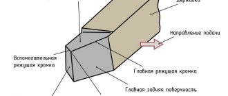
Image #1: Lathe cutter design
Geometry of turning tools
Image No. 2: turning tool geometry
Let's talk about the angles of the incisors and their purposes.
- Back auxiliary angle (α1). As it decreases, the friction force between the rear plane of the tool and the workpiece decreases.
- Apex angle (ε). Formed between the cutting edge and the rear auxiliary plane. The larger this angle, the better the heat removal conditions and the higher the strength of the cutter.
- Auxiliary plan angle (ϕ1). Its size varies from 10 to 30°. As the angle decreases, the cleanliness of the treatment improves, but the friction force increases.
- Leading angle (ϕ). Its size varies from 20 to 90°. The length and width of the cut depend on the size of the angle. The smaller ϕ, the lower the temperature and cutting force. The cleanliness of the processing is also improved. But as the angle decreases, vibration and radial cutting force increase.
- Cutting angle (δ). Formed between the rake surface and the cutting plane.
- Basic rake angle (γ). Its size varies from -5 to +15°. As the angle increases, it is easier for the tool to cut into the metal, chip removal is improved, and the cutting force, deformation of the machined surface, and power consumption are reduced. However, this reduces heat dissipation and reduces the service life of the cutting edge.
- Taper angle (β). Formed between the front and main back surfaces. Affects the sharpness and strength of the tool.
- Main relief angle (α). Its size varies from 6 to 12°. As the angle decreases, the friction force between the part and the back surface of the cutter decreases. This improves heat dissipation and extends the service life of the tool, but the cleanliness of the machined surface deteriorates.
- Angle of inclination of the main cutting edge (λ). Affects the direction of chip removal. At positive λ and λ = 0°, the chips move towards the machined surface. Cutters with positive λ (12–15°) are used when processing workpieces made of heat-resistant and hardened steels. For universal turning tools, λ = 0°. Cutters with negative λ are used for finishing.
Classification and types of incisors
According to design parameters:
- Whole (one-piece). The cutter head is made as a single unit with the rod (holder). As a rule, such cutters are made of carbon tool steel or high-speed steels (for small cutters).
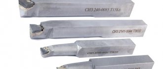
- With welded or soldered plates. The cutter head includes a welded or soldered plate made of high-speed steel or hard alloy (T5K10, T15K6, VK8, etc.). They have a wide range of applications.
- With mechanical fastening of plates. The insert is fixed in the cutter head mechanically. This method is especially useful for plates made of mineral-ceramic based material.
By feeding direction:
- Rights. The main cutting edge of the cutter, facing the surface of the workpiece, is located on the left side.
Left. The main cutting edge of the cutter, facing the surface of the workpiece, is located on the right side.
According to the location of the main cutting edge relative to the cutter shaft:
- Direct. The projection axis of the cutter part in the top plan and side view has a straight line.
- Bent back. The projection axis of the cutter part in the top view has a curved line, and in the side view it has a straight line.
- Curved. The projection axis of the cutter part in the top view has a straight line, and in the side view it has a curved line.
According to the material from which the working part is made:
From hard alloys:
- VK8 – tungsten cutters (designed for processing parts made of cast iron, non-ferrous metals and their alloys, as well as non-metallic materials);
- T15K6, T5K10, T14K8, T30K4 – titanium-tungsten cutters (used for processing all types of steel);
Made from high-speed steel grades:
- Р6М5, Р18, Р12 and Р9 – cutters of normal productivity;
| Material | Application |
| For processing materials by cutting | |
| VK8 | Rough turning with uneven cut section and intermittent cutting, planing, rough milling, drilling, rough drilling, rough countersinking of gray cast iron, non-ferrous metals and their alloys and non-metallic materials. Processing of stainless, high-strength and heat-resistant difficult-to-machine steels and alloys, including titanium alloys |
| T15K6 | Semi-rough turning during continuous cutting, finishing turning during intermittent cutting, threading with commercial cutters and rotary heads, semi-finishing and finishing milling of solid surfaces, drilling and boring of pre-machined holes, finishing countersinking, reaming and other similar types of processing of carbon and alloy steels |
| T5K10 | Rough turning with uneven cut section and intermittent cutting, shaped turning, cutting with turning tools; finishing planing; rough milling of discontinuous surfaces and other types of processing of carbon and alloy steels, mainly in the form of forgings, stampings and castings on crust and scale |
| T30K4 | Finish turning with a small cut section (diamond cutting type); thread cutting and reaming of unhardened and hardened carbon steels |
| T14K8 | Rough turning with an uneven cut section and continuous cutting, semi-finish and finishing turning with intermittent cutting; rough milling of solid surfaces; drilling cast and forged holes, rough countersinking and other similar types of processing of carbon and alloy steels |
Marking of turning tools, meaning of numbers and symbols
According to the standard, the marking of turning tools may include 9 or 10 characters.
- The first is the method of attaching the cutting insert.
- The second is its shape.
- The third is the type of cutter.
- The fourth is the rear corner of the cutting insert.
- Fifth - cutting direction.
Image No. 6: possible values of parameters 1–5
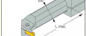
- The sixth is the height of the holder.
- The seventh is the width of its tail section.
- The eighth is the total length of the incisor.
- The ninth is the size of the cutting plate.
Image No. 7: possible values of parameters 6–9
- The tenth is indicated if necessary. Indicates the accuracy of some cutter parameters.
Image No. 8: possible values for parameter 10
Turning cutters. Basics of the metal cutting process
Conditions for high productivity of mechanical cutting tools
The action of cutting tools used on metal machines, in particular turning tools, depends on three main conditions: 1) on the stability of the workpiece, i.e. on the strength of its material and the method of fixing it on the machine; 2) on the strength of the tool, in other words, on its size and method of fastening; 3) on the shape of the cutting part of the tool.
Proper stability and strength of the machine is also, of course, necessary.
The person working on the machine usually has to sharpen and install the cutters required for the job himself, and therefore he must be well acquainted with the requirements for them.
Turning cutters
Forged turning tools
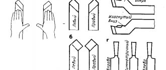
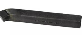
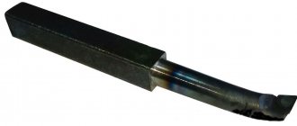
- The scoring cutter (on the right in the figure) is used for end (frontal) turning. Has side and front clearance. The cutting edge is sharpened at such an angle that the cutter does not touch the rear center of the machine when approaching the center of the surface being ground. The cutter has only a transverse slope. There is no longitudinal slope.
- The sharp-nosed incisor (right in the figure) is now rarely used, as it has been replaced by “normal” Taylor incisors.
- Curved, sharp-nosed incisor (left in the picture). The ends of most types of incisors often bend to the right or left. For some jobs, eg when processing shoulders, this is convenient.
- Normal through cutter. This type of cutter was developed by Taylor as a result of many years of experience, which showed that this form of cutter is the most advantageous for turning. The average longitudinal slope is 8°, the average transverse slope is 14°. In what follows, for brevity, this incisor is called “normal.”
- Cut-off cutter. Discussed in detail in §§ 147 and 148.
- Round-nosed incisor. The cutting edge is rounded to an arbitrary radius, which distinguishes it from a normal cutter. Used for cutting semicircular grooves, fillets (fillets), shoulders, etc.
- Brass cutter. It is sharpened like a type 6 cutter, the tip of which is rounded to a small radius. It has neither longitudinal nor transverse slope, in order to avoid cutting the cutter into soft brass.
- Wide finishing cutter. Very useful for aligning front centers and turning short tapers. It is often used with large feeds to remove the finest finishing chips from cast iron. It has no longitudinal slope.
- Spring cutter. For turning wide shoulders and other shaped work where it is necessary to remove wide chips, as well as for finishing cast iron and steel (with water). When this cutter springs, its cutting edge moves away from the surface being processed.
- Flat (blunt-nosed) incisor. Very convenient for frontal turning of large diameter ends when a lot of metal needs to be removed. Feed from the circumference to the center. It is also used for finishing steel, with large feeds and small depths of cut (“thin chips”). For the cleanest finish, cool with water and soda. It has only a longitudinal slope, no transverse one. Lateral clearance - on both sides, therefore, can work as a right-handed or left-handed cutter.
- Centering cutter (cutter-drill). It is sharpened at an angle of 120°—corresponding to the angle of the tip of the twist drill. Works similar to the perk. The gap of both cutting ribs is directed in opposite directions. Used to mark the center of holes to be drilled with a twist drill.
- Cutter for cutting screw threads. Its toe is sharpened exactly according to the thread profile. For details, see chap. 16,
- Boring cutter. See § 162.
A lathe is used for a wide variety of work - turning, threading, boring holes, etc., and each operation requires specially shaped cutters. In fig. 62 shows various types of forged turning tools. However, recently they are gradually being replaced by more economical cutters of small sizes, inserted into special holders (see Fig. 66).
The basic principles underlying the choice of cutter sharpening angles, clearance angles, etc., set out in further paragraphs, are common to all metal cutting tools. Anyone who knows why a turning cutter is sharpened this way and not another, knows why certain bevel angles are chosen, etc., and knows how to hold the cutter on a grinding wheel while sharpening, will quickly learn how to properly sharpen other tools and understand which they must have a form.
The material from which the cutters are made must be sufficiently hard and tough to withstand the forces exerted on the cutter during cutting. Therefore, metal cutting tools are made of steel, hardened and then tempered.
Cutter point angle
The action of each cutting tool is similar to the action of a wedge, which pushes the particles of material apart. In relation to the cutters, the angle of the wedge formed by its edges is called the point angle of the cutter or, in short, the angle of the cutter (see Fig. 63).
The harder the material being processed, the stronger the cutter blade should be, i.e. the greater the angle of its sharpening should be. The angle of the cutter, suitable for wood, is not suitable for processing iron or steel, since its value will soon change due to the fact that the cutting edge will round off (“give in”) under the influence of the high cutting resistance of the metal. For metal cutters, the sharpening angle is made from 60° to 80°, depending on the hardness of the metal being processed.
Clearance angles
The action of a cutter removing shavings from metal is similar to the action of a knife used to peel an apple. The chips being removed rub against one of the faces forming the wedge, while the other face should not touch the product and therefore makes a certain small angle with it, the so-called. side clearance angle (Fig. 63). This angle should not, generally speaking, be more than 6°, since as it increases, the angle of the cutter decreases, therefore, the cutter will have to be sharpened more often.
The action of the cutting resistance force on the turning cutter is directed tangentially to the circumference of the workpiece being turned at the point of contact of the cutter with the workpiece (see Fig. 64). Since the top is the so-called. the toe of the cutter is usually installed at the height of the center line or slightly above it, then in order to avoid friction between the product and the front edge of the cutter, this face is given some slope. The angle between the rake face and the cutting direction is called the rake clearance angle or, in short, the clearance angle. Its usual value is about 10°. However, it depends on the height of the cutter in the support.
Cutting edge slope angles
In order to obtain the required sharpening angle, it is necessary to grind off the upper (cutting) edge of the cutter so that it has both a longitudinal slope - from the cutting edge back - and a lateral slope - from the cutting edge in the direction opposite to the feed. Otherwise, the sharpening angle of the cutter will not be sharp enough. The slope from the toe of the cutter back is called the longitudinal slope angle of the cutting edge, and the lateral slope is called its transverse slope angle (Fig. 65). The magnitude of these angles depends, naturally, on what sharpening angle is required, since the greater the slope, the smaller the angle of the cutter, i.e. the sharper the cutting wedge formed by its edges. For turning cast iron and tool carbon steel, the cutter angle should average about 70°, for mild semi-finished steel - 60°. When sharpening a cutter, first remove the clearance angle, then the slope angles, in such a way as to obtain the sharpening angle required for processing the material.
Compared to steel, brass is a soft metal and therefore, to process it, it would not be necessary to give the cutter the same large sharpening angle as a cutter for steel. However, in reality, bevel angles are usually not sharpened on brass cutters, since sharp cutters tend to “eat in”, i.e. delve into soft material.
Tool holders
High speed steel cutters are approximately twice as productive as carbon tool steel cutters. Therefore, recently turning cutters, as well as other cutting tools for metal processing, have been made mainly from high-speed steel. Since it is much more expensive than carbon steel, various holders have become widespread, in which a small piece of high-speed steel, sharpened accordingly, is securely fixed. This results in savings not only on the cost of steel, but also on the costs of forging cutters.
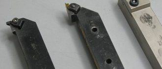
In fig. Figure 66 shows several common types of tool holders. In fig. 67 are shown on the right - inserted turning cutters (plates) made of high-speed steel, sharpened for various jobs, on the left - the operation of these cutters mounted in holders.
Sharpening cutters
A properly sharpened cutter, when used under normal conditions, remains sharp for quite a long time. As soon as it shows signs of dullness, it is necessary to immediately resharpen it, otherwise not only the cutter will suffer, but also the product being processed by it. A dull cutter does not so much cut metal as tear out particles of it, so the surface being processed cannot be smooth. One of the main factors in the productive operation of the machine is a sharply sharpened cutter.
It must be remembered that improper sharpening of cutters places a heavy burden on the cost of products simply by the cost of excessively worn material of cutters and grinding wheels. Where should the cutter be sharpened - from above, from the front, from the side, or from all sides a little? It is impossible to give definite rules in this regard, and when sharpening a cutter you should proceed from the work for which it is intended. The method of sharpening largely depends on how long the cutter should work without regrinding and how long it should last in total.
When sharpening a carbon steel cutter, you should not press it too hard against the grinding wheel, otherwise the cutting edge will heat up (usually it turns blue) and release, i.e. its hardening will be lost. It is preferable to use a wet sharpener. High-speed steel cutters do not lose their hardening so easily, but sometimes, if there is not enough water, cracks appear on their surface. Therefore, firstly, you should not spare water, and secondly, you should not press too hard on the cutter while sharpening.
Do not keep the cutter in one place, move it so that it is pressed against different places on the cylindrical surface of the circle. In this case, the cutter must be gradually rotated, as shown in Fig. 68, i.e., so that it takes sequential positions a, b, c.
Small cutters should not be sharpened in holders, because, firstly, it is inconvenient, and secondly, the end of the holder can be ground down at the same time. In fig. 69 shows how to hold such cutters while sharpening.
It is recommended for a beginner to practice first on small pieces of simple ornamental steel of a suitable shape and only then proceed to sharpening high-speed steel insert cutters. At first, obtaining the correct clearance angle on such a cutter by sharpening presents some difficulties, since for work the cutter is inserted into the holder at a known angle. Therefore, at first, while there is no skill, it is best to use a template. In cases where it is necessary to obtain a relief angle of 10°, it is convenient to use a template for turning centers (see Fig. 85), the angle of which is 60°, since in most holders the cutter is fixed so that its upper edge is 20° with the horizontal (Fig. 70). If the cutter angle is other than 60°, it is not difficult to cut a corresponding template from a piece of sheet metal.
What not to do when sharpening a cutter
- Don't sharpen the cutter at random; be aware of where and how much metal needs to be removed.
- Hold the cutter firmly and confidently.
- Do not press the cutter to the circle with your left hand; hold it properly, that's the easiest thing.
- Don't skimp on water.
- Do not keep the cutter in one place on the grinding wheel all the time, otherwise you will cut a groove on it.
- If possible, do not use a circle that has lost its correct cylindrical shape or whose surface is heavily chipped.
- Do not sharpen a cutter on the end surface of a circle unless necessary: when you need to sharpen on the end, its surface will no longer be flat, but scratched by you or someone else.
- Do not rest the insert cutters on the tool rest: hold them in your left hand and rest your hand on the tool rest.
- Do not move the tool rest further than 1.5-2 mm from the grinding wheel.
- Do not round the tip of a thread cutter or turn a round nose cutter into a thread cutter: this is a waste of material and time.