Due to the peculiarities of their design, groove cutters (also called slotting cutters) are considered multifunctional tools that can be used to form grooves on workpieces of cylindrical and conical configurations. Such technological operations (especially those associated with radial grooving) are characterized by significant loads, which are successfully carried by a cutter of this type, characterized by high structural rigidity. Moreover, groove cutters are successfully used for axial grooving and facing, making them versatile turning tools.
Grooving cutters for internal and external grooves with mechanical fastening of replaceable cutting inserts
It is advisable to use groove turning tools to obtain parts with complex configurations. The versatility of cutters of this type in such cases allows us to minimize the number of tools used and reduce the time for equipment changeover. It is also noteworthy that the use of a groove cutter when performing many technological operations makes it possible to form surfaces with higher quality characteristics than when using a conventional turning tool.
Particularly successful is the use of a groove cutter when creating wide grooves on the surface of workpieces. When performing this technological operation, such a tool demonstrates exceptional durability; wear of its cutting plate occurs evenly even when performing a large number of passes. What is also important is that when using a groove cutter, the chip separation process is well controlled.
Requirements for groove-type cutters, which are produced in a wide variety of standard sizes, are specified by the provisions of GOST 18874-73.
GOST 18885-73 and 18874-73 regarding groove cutters
The contents of GOST 18874-73 “Slotting and parting cutters made of high-speed steel” and GOST 18885-73 “Threaded turning cutters with hard alloy plates” can be found below:
GOST 18874-7
GOST 18885-73
Damn.3
Type 3
______________
* At a length not less than the thread pitch.
Damn.3
Table 5
Dimensions in mm
| Cutter section | Designation of plates according to GOST 25422-90, GOST 25412-90 | |||||||
| 0,60 | 11,3 | 0,75 | 48010 | |||||
| 0,96 | 1,00 | |||||||
| 20x12 | 1,33 | 15,3 | 1,25 | 18,0 | 48030 | |||
| 1,56 | 1,75 | |||||||
| 25x16 | 0,25 | 1,93 | 16,9 | 2,00 | 22,0 | 48050 | ||
| 2,67 | 2,50 | |||||||
| 13,0 | 3,39 | 18,9 | 3,00 | 29,0 | 48090 | |||
| 32x20 | 4,12 | 3,50 | ||||||
| 18,0 | 5,32 | 23,7 | 5,00 | 28,5 | 48130 | |||
| 40x25 | 0,50 | 22,0 | 6,78 | 10,0 | 30,7 | 6,00 | 37,0 | 32230 |
| 28,0 | 8,24 | 12,0 | 34,7 | 7,00 | 32250 |
Types of groove cutters
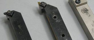
Turning tools for forming grooves include cutters for internal and external machining. Both the first and second can be made entirely of carbide materials or have a replaceable cutting part. Carbide cutters are a fairly expensive tool, so their use must be economically feasible. When performing external work, products with replaceable inserts are usually used; using carbide groove cutters in such cases does not make sense.
The situation is completely different with the processing of internal grooves. Here it is necessary to take into account the diameter of the hole into which the cutter is to be inserted, as well as the rigidity of the tool. The requirements for a cutter to have a minimum size of its holder and sufficient rigidity to perform metal processing are met only by carbide groove tools.
Naturally, when the processing conditions and geometric parameters of the workpiece allow it, it is more advisable to use an inexpensive tool with replaceable inserts to form external and internal grooves.
Tips for choosing quality cutters when purchasing
To choose the right cutters for a particular case, you need to rely on the following important parameters:
Which metal is processed most often? What operations are performed on the equipment? It is important to prioritize in advance between wear resistance, processing efficiency and product quality.
If a turner is just starting to work, then he only needs to purchase three types of tools:
- Boring SDQCR.
- Neutral external type
- Pass-throughs for processing ends. SDACR.
Sets with lathe cutters are relevant if long-term operation is planned. The advantage is kits with replaceable plates. There is no need to purchase new holders; it is enough to change the consumable components.
As for manufacturers, here are a few names worthy of attention:
- Caliber.
- Sieve.
- Proma from the Czech Republic.
- Hoffman Garant from Germany.
The first two manufacturers are Russian. It would be important to purchase a special sharpening machine. Then, if the incisors wear out, returning them to working capacity on your own will not be a hassle. No need to waste time waiting for the masters.
Two wheels with abrasive properties and support for the cooling system are becoming important components for modern sharpening and grinding units. One disk is made of silicon carbide, the other is based on electrocorundum. The front part of the cutter is processed first, followed by the rear surfaces and the addition. The goal is to obtain a smooth edge that can cut through materials.
Geometry and dimensions of groove type cutters
Since groove-type cutters experience significant load during processing, which determines increased requirements for their rigidity, they are manufactured with soldered carbide plates, the characteristics of which are specified in GOST 2209-82. The requirements for the cutter itself, as stated above, are given in GOST 18874-73.
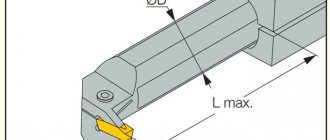
The main feature of the geometry of groove-type cutters is that the shape of their cutting part must exactly match the shape of the groove that is planned to be obtained with their help. The grooves created on the surface of the workpiece are usually small in width. Accordingly, the cutting part of the tool with which they are formed is also quite narrow, which makes it very vulnerable to mechanical damage. In addition, the working head on each side has a narrowing towards the holder (by 1–2 degrees). Such a narrowing of the sides of the cutting part is necessary in order to reduce their friction against the walls of the groove being formed.
Geometric parameters of the groove cutter
To increase the strength of the cutting head of a groove turning tool, its height is made significantly larger than its width. This also requires a small rake angle and a sharpening of the cutting edge with a small radius (curvilinear). The optimal cutting angles for groove-type cutters are 15–250 (front), 8–120 (rear).
The width of the working part of the groove tool, which, according to the requirements of GOST 18874-73, can vary over a wide range, is selected depending on the width of the groove that needs to be formed on the outer or inner surface of the workpiece.
Damn.2
Type 2
_______________
* At a length not less than the thread pitch.
Damn.2
Table 3
Dimensions in mm
| Cutter section | Designation of plates according to GOST 25398-90 | |||
| 10x10 | 11150 | |||
| 12x12 | 10,5 | |||
| 16x16 | 13,5 | 11190 | ||
| 20x20 | 12,5 | 11,5 | 17,5 | 11210 |
| 25x25 | 16,0 | 15,0 | 22,0 | 11230 |
Table 4
mm
| Thread pitch | 0,75 | 0,80 | 1,00 | 1,25 | 1,50 | 1,75 | 2,00 | 2,50 | 3,00 | 3,50 | 4,00 | 4,50 | 5,00 | 5,50 | 6,00 |
| 0,050 | 0,055 | 0,072 | 0,090 | 0,110 | 0,125 | 0,145 | 0,18 | 0,215 | 0,250 | 0,288 | 0,325 | 0,360 | 0,400 | 0,430 |
Selection rules
The first thing you should focus on when choosing a groove turning tool is a drawing of the finished product, which indicates both the dimensions and shape of the grooves, as well as the tolerances for the accuracy of their geometric parameters. Naturally, the choice of cutter and its geometric parameters is influenced by the material from which the workpiece is made.
External groove cutter
When forming grooves on small parts, it is especially important to maintain a low cutting force, which minimizes the distortion that occurs during processing. Compliance with this requirement is ensured by the sharp sharpening of the groove tool, which, however, can lead to its breakage if the carbide plate material and cutting conditions are selected incorrectly - the rotation speed of the workpiece and the feed rate.
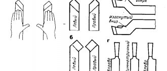
When choosing a groove cutter, you should also take into account the shape of its cutting edge, which can be straight and sharpened with a small radius. Naturally, you should not choose a product with a curved sharpening of the cutting edge if the bottom of the groove, according to the provided drawing, should be straight.
Internal groove cutter
Wood cutters for a lathe: purpose and design of elements
The main purpose of wood turning tools is manual processing of a part rotating in a special machine. The lathe used for these purposes is designed to impart rotation to the body. Wooden blanks, which are initially round in shape, are mounted on a lathe using two clamps. One clamp is connected to an electric motor, which sets the part in motion.
The choice of the type of turning cutter, its sharpening and condition largely determines the possibility of certain operations and the manufacture of parts of the required configuration
Important! On the motor side, the fixation must be rigid so that rotational movements do not occur at idle. Cutters, which are fixed to the rotating mechanism, perform processing of a rotating body
Depending on the strength, shape and sharpness of the cutter, marks are formed on the wooden workpiece. This also determines the shape of the workpiece
The cutters, which are fixed to the rotating mechanism, perform processing of the rotating body. Depending on the strength, shape and sharpness of the cutter, marks are formed on the wooden workpiece. This also determines the shape of the workpiece.
The design of a lathe cutter consists of a working metal part and a wooden handle. The working element conventionally consists of a blade, body and shank. The blade consists of a front, back and pointed angle. The size of the sharpening angle depends on the material of the workpiece. Most often, craftsmen use sharp corners when working with wood. The body is the main part for which the turner holds the cutter on the armrest of the machine with his non-working hand. The shank is a narrowed part into which the body of the tool goes. It is on this that the handle of the turning tool is attached.
The handle structure consists of a base and a neck. The base is the larger part of the handle that the turner holds with his hand. The neck is represented by a small cylindrical part with a metal fastening ring. It is designed to prevent the handle from cracking while being pressed onto the shank of the working part.
Wood turning tools consist of a back corner, a pointed corner and a rake corner.
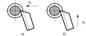
Features of turning using a groove cutter
The cutting modes when using groove-type cutters have some differences from the modes of processing the workpiece with other types of turning tools. Thus, the depth of cut is taken to be a value equal to the width of the groove being formed, and the tool feed per revolution of the part is measured in the direction perpendicular to its axis. The feed rate, depending on the material from which the cutting part of the groove tool is made, is selected in the range of 0.07–0.2 mm/rev, and the cutting speed is 15–180 m/min.
Several types of grooves can be obtained on the surface of the workpiece.
- Narrow grooves, the width of which corresponds to the width of the cutting part of the tool, are made in one pass of the cutter, which is fed manually. Before this, the exact location of the groove is determined on the surface of the part, and then the cutter is placed opposite this place and fed.
- The grooves on the ledges and ends of the part are made according to the same principle; their diameter is set using the transverse feed dial, and their depth is set using the longitudinal movement dial of the caliper.
- Wide grooves are made in several passes according to the following scheme. First, determine the location of the right edge of the groove and place the cutter opposite this location. Using a transverse feed, the cutter is cut into the part to a depth that is 0.5 mm less than the depth of the groove being cut (this allowance is left for finishing). Then, using a longitudinal feed, the groove tool begins to move to the left edge of the groove being cut, the boundary of which has been previously marked. After the rough groove is formed, its bottom is processed cleanly - to the required depth, carrying out the longitudinal feed of the cutter from left to right. In the event that it is necessary to form a groove with a very precise location of its left and right edges, allowances can also be left on them during roughing, which are then removed using the transverse feed of a groove or scoring cutter.
Types of work performed by grooving cutters
Damn.1
Type 1
_______________
* At a length not less than the thread pitch.
Damn.1
Table 1
Dimensions in mm
| Cutter section | Designation of plates according to GOST 25398-90 | |||
| 16x10 | 13,5 | 15,5 | 11130 | |
| 20x12 | 15,0 | 16,0 | 19,0 | 11190 |
| 25x16 | 18,6 | 20,0 | 22,5 | 11210 |
| 32x20 | 23,3 | 26,0 | 29,0 | 11230 |
table 2
mm
| Thread pitch | 0,50 | 0,75 | 0,80 | 1,00 | 1,25 | 1,50 | 1,75 | 2,00 | 2,50 | 3,00 | 3,50 | 4,00 | 4,50 | 5,00 | 5,50 | 6,00 |
| 0,072 | 0,108 | 0,115 | 0,144 | 0,180 | 0,216 | 0,252 | 0,288 | 0,360 | 0,432 | 0,504 | 0,576 | 0,648 | 0,720 | 0,792 | 0,870 | |
| 0,047 | 0,079 | 0,085 | 0,113 | 0,146 | 0,179 | 0,213 | 0,249 | 0,317 | 0,389 | 0,459 | 0,529 | 0,601 | 0,670 | 0,742 | 0,812 |
Labeling and manufacturers
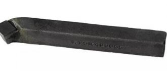
The description of groove turning tools will be incomplete without mentioning the markings, which determine the composition of the material of their cutting part. For example, the T5K10 cutter is made of a hard alloy of the titanium-tungsten group, which contains 5% titanium carbide and 10% cobalt. The markings of products made from other materials are deciphered in a similar way.
The most famous manufacturers of grooving turning tools are:
- Dnepropetrovsk industrial tools plant (Ukraine);
- (Ukraine);
- Zenitech company (Switzerland);
- Proma company (Czech Republic);
- Itertool company (China).
Main purpose of the tool
This cutting tool is used in mechanical engineering on a variety of machines: milling; planing; slotting; turning
With the help of this tool, a wide variety of parts are processed with a certain precision. To obtain a product of the desired shape, several layers of metal are removed from the part. To do this, it is firmly fixed in the tool holder.
The working surface of the tool has a very sharp edge, reminiscent of a wedge. It cuts into the workpiece and deforms its outer surface. As a result, it begins to chip. The front surface of the tool shifts it, turning it into chips.
The forward movement continues, the chipping process does not stop, and chip formation continues. Its appearance greatly depends on several factors:
- Part rotation speed.
- Innings.
- coolant
Depending on the type of operation, equipment is divided into several types:
- Turning.
- Slotting.
- Planing.
To move the workpiece together with the tool in the horizontal direction, a planing cutter is installed. If cutting occurs vertically, use a slotting device. Both devices work on the same principle. They differ from similar turning equipment, since on this machine the cutting process occurs continuously. When planing or chiselling is performed, plunging occurs only during the working stroke.
According to the technological process, the processing of a workpiece can have several operations:
- Chernova.
- Semi-finish. The cutter has a cutting plate with a rounded cutting edge. As a result, the surface roughness is improved.
- Finishing.
- Fine turning.
Blind hole machining
Very often there are designs where the parts do not have through holes. To bore them, a special boring cutter for blind holes is used. All types of such instruments are standardized. In GOST you can see the dimensions of the cutter, as well as its design.
When it comes to processing blind holes, a cutting insert in the form of a triangle is installed. For ease of use, the working part of the holder has a slight bend. Based on the diameter of the hole, the corresponding dimensions of the holder are selected.
Boring through holes
To use a curved cutter, a hole is pre-drilled into the part. Its depth is directly dependent on the size of the holder. The longer it is, the greater the depth of the hole. The thickness of the layer of metal removed during this treatment is approximately equal to the amount of bending of the cutting part.
Boring tool for working on a lathe
Turning of parts is considered one of the most important operations in mechanical engineering. Using a boring tool, blind or through holes are processed.
The use of boring tools makes it possible to obtain high processing accuracy and excellent surface roughness. Boring operations are performed only in certain situations:
- When drilling does not provide accurate dimensions and the required surface cleanliness.
- The required tool is not available to obtain the required diameter.
- It is necessary to obtain a straight hole with the exact location of the axis. The diameter of the hole being machined is much larger than the standard drill size.
- Very short hole length.
For processing non-ferrous metals, plastics and other light materials, cutters are used, for the manufacture of which tool steel is used. If a carbide insert is installed in the work head, durable stainless steel is used.
During operation, the cutting part begins to wear out, and the carbide plate begins to chip. The cutters have to be sharpened.