Due to the peculiarities of their design, groove cutters (also called slotting cutters) are considered multifunctional tools that can be used to form grooves on workpieces of cylindrical and conical configurations. Such technological operations (especially those associated with radial grooving) are characterized by significant loads, which are successfully carried by a cutter of this type, characterized by high structural rigidity. Moreover, groove cutters are successfully used for axial grooving and facing, making them versatile turning tools.
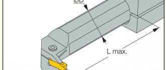
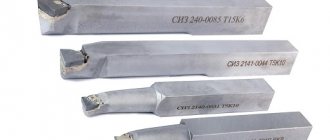
Grooving cutters for internal and external grooves with mechanical fastening of replaceable cutting inserts
It is advisable to use groove turning tools to obtain parts with complex configurations. The versatility of cutters of this type in such cases allows us to minimize the number of tools used and reduce the time for equipment changeover. It is also noteworthy that the use of a groove cutter when performing many technological operations makes it possible to form surfaces with higher quality characteristics than when using a conventional turning tool.
Particularly successful is the use of a groove cutter when creating wide grooves on the surface of workpieces. When performing this technological operation, such a tool demonstrates exceptional durability; wear of its cutting plate occurs evenly even when performing a large number of passes. What is also important is that when using a groove cutter, the chip separation process is well controlled.
Requirements for groove-type cutters, which are produced in a wide variety of standard sizes, are specified by the provisions of GOST 18874-73.
Geometric parameters and tool dimensions
The design of any groove cutter is characterized by its geometric parameters.
- Geometry of the body or holder: L – length of the body, B and H – dimensions of the cross-sectional sides.
- Location of the cutting element in the body. The socket for the plate can occupy the entire width of the case or one of the corners. In the latter case, the width of the socket is indicated by the letter n. The plate can be placed in the socket at a certain angle to the body.
Shape of the working cutting plate: l – length of the working part of the cutter, b – height of the plate body, S – thickness.
The blade for cutting the workpiece also has its own parameters, expressed in angles.
- “Gamma” displays the front sharpening angle - this is the main element of the cutting edge.
- “Alpha” is the rear main sharpening angle.
- “Alpha” with index 1 is the rear corner for auxiliary purposes.
- "Lambda" is the angle at which the cutting edge is inclined.
- “Phi” is the main purpose angle located in plan.
- “Phi” with index 1 is an auxiliary angle located in plan.
Types and purpose of turning cutters
In the generally accepted classification of metalworking tools, cutters are divided into groups that differ in processing methods and technologies. The name of the device reflects the essence and purpose of the tool. For example, boring cutters are used to work with through holes.
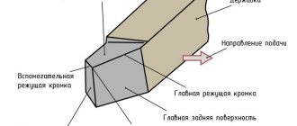
The design of a cutting tool, regardless of its type, consists of two parts:
- Holder. This part is fixed in the lathe chuck of the machine or in another mechanism provided for by the design of the machine.
- Head. A working element that is in direct contact with the workpiece being processed. Consists of several planes with cutting edges. The sharpening angle depends on the design requirements.
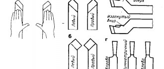
Based on their appearance, turning cutters are divided into the following groups:
- Direct. The classic shape, in which the holder and the cutting part are located on the same axis.
- Curved. The holder of these cutters has one bend, the location and angle of which depend on the type of tool.
- Bent back. In this case, the working head has some displacement relative to the axis of the fastening part.
- Retracted. This type of design is characterized by the width of the working part, which is smaller than the holder. This allows you to perform work in hard-to-reach places with a small area of impact on the surface.
Among the instruments under consideration, there are several types. Let's take a closer look at them.
Pass-through bent
A universal type cutter is used to chamfer products, process the end parts of parts and perform other work. The direction of bending depends on the specifics of the work. Pass-through bent cutters are used for both roughing and finishing of metal.
Manufacturers are required to follow the requirements of interstate standard 18868-73.
They produce many models that differ in product dimensions. The most common dimensions are the following (height*width*length, mm):
- 16*10*110;
- 25*20*170;
- 32*25*170;
- 40*32*240;
- 50*40*240.
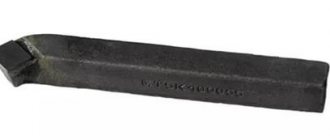
Pass-through persistent
Manufacturers do not recommend processing parts with high rigidity with this cutter.
They produce right- and left-handed models. It is noteworthy that square cutters with dimensions 20*20 and 50*50 can only be persistent left, without reverse bending.
Markings used
The designation of groove cutters is encoded, which provides a complete definition of the geometric parameters of the tool included in the tables of regulatory documents. The main product markings mention parameters such as the alloy with the percentage of metal components in the alloy. For example, if you take a T5K10 cutter, then there will be an alloy based on the titanium-tungsten group, where titanium carbide is up to 5%, and cobalt is up to 10%.
To select cutting groove products, it is not enough to know only the composition of the alloy; you need to proceed from all the parameters specified by GOST.
Prefabricated structures
Speaking about the types of devices for metal processing, it should be noted that cutters have a prefabricated structure. This instrument is considered universal because you can put almost any records in it. For example, by fixing different types of cutting blades in one holder, you can make a device for working with metal workpieces at different angles and with different levels of productivity.
In most cases, these types of cutters are used on machines equipped with CNC, or for boring through and blind holes, contour high-precision turning and other work.
GOST standards for groove cutters
Regulatory documents have been developed for groove cutters of various modifications:
- GOST 18874-73 regulates the standards for cutting and slotting equipment, which specifies the dimensions and design of the tool, which is made of high-speed steel.
- GOST 18885-73 describes the design features of groove cutters for thread production, which are equipped with carbide plates.
- GOST 18884 - 73 - this normative act gives instructions on the size and design of cutting tools for turning, the plates of which are tipped with carbide alloys.
- GOST 28978-91 - the document defines the standard for prefabricated groove cutting tools.
Features of turning using a groove cutter
The technological cycle of turning operations has its own specifics, which depend on the machine fleet, the materials processed and the complexity of the parts produced. The work begins with analyzing the sketch of the part and breaking it down into elementary operations using one tool. If there are a large number of parts of the same type, it makes sense to perform one operation for all of them at once, without changing the tool. For example, it is necessary to make a selection at the end of a dozen workpieces: a cutter for end grooves is installed, the tool is adjusted to the specified dimensions, and all parts are drilled.
The speed of grooving with a cutter directly depends on the capabilities of the equipment: at low speeds it is not possible to process hardened workpieces or obtain a shaped surface. A spindle with play leads to runout of the workpiece, and as a result, it is not possible to comply with the specified parameters and tolerances. In the worst case scenario, the part can jam and break the cutter head or injure the operator. In many production shops there are machines manufactured in the USSR that have long exhausted their resources; it is very difficult to maintain tight tolerances on them - the feed calipers simply cannot provide the standard 0.07-0.2 mm/rev feed. On such machines, it is optimal to use groove cutters of a composite design with cutting plates that are relatively easy to change and sharpen.
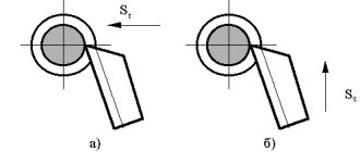
In general, deep grooves are drilled using roughing (roughing) and finishing (semi-finishing) tools. First, the cut is made rough, leaving about 0.5 mm to the specified dimensions, the remainder is removed with a finishing tool. In the case of very tight tolerances, fine turning cutters are used; the outer surface is processed with radial cutters when the tool is perpendicular to the turning axis. For machines operating in automatic or semi-automatic mode, it is typical to use tangential cutters; the feed caliper moves parallel to the axis of the workpiece; in this mode, high surface cleanliness can be achieved.
Recommendations for selecting groove cutters
When choosing a groove cutter, you should be guided by the following considerations:
- First of all, they analyze the drawing according to which the part will be manufactured. The drawing shows all the parameters of the grooves: width, depth, shape, as well as standards for manufacturing accuracy and possible tolerances.
- The metal from which the part is made. For carbide metals, appropriate cutters with a carbide blade are used; for soft metals, ordinary grooved ones are used.
- When choosing a tool for cutting grooves inside a hole, the diameter of the holder and the size of the protruding edge of the knife are important. Here, too, it is more advisable to use carbide equipment.
- Equipment for carrying out operations. The choice of groove cutter is determined in this case depending on the possible operating modes of the machine, the configuration and type of tool holder.
- Features of the technological process. The technical process can affect the processing speed of the product. The higher the speed, the stronger and more durable the grooving equipment must be used to achieve processing goals.
- Is there any provision for lubrication of the treatment area during the operation? Lubrication has a positive effect on the work, removing part of the load from the groove tool and thereby making it possible to use simpler equipment.
How to install a parting cutter
In order to perform cutting correctly without increased wear of the cutting plate, as well as to ensure the required quality of the end after cutting, it is necessary to align the cutter strictly perpendicular to the part. In addition, it must be installed opposite the axis of rotation with a vertical deviation of no more than ± 0.1 mm. Placing the edge of the blade even a few tenths of a millimeter higher can cause the cutting blade to break, and placing it too low can leave an uncut step on the workpiece. Cutting must be done as close to the chuck jaws as possible, using a cutter with a minimum overhang.
Main advantages
The use of replaceable carbide inserts allows you to reduce the cost of purchasing tools. If necessary, you can simply replace the worn plate; the holder is made of ordinary structural steel. It is cheaper than purchasing a solid cutter. The next advantage is saving time. The same cutter can be used for different operations with a simple insert change. In this case, no additional soldering or sharpening is required, and the cutting mode can be changed almost “on the fly.” Thanks to unification, the process of selecting plates is simplified and time spent on processing parts is reduced.