GOST 20872-80
GOST 20872-80 Group G23
INTERSTATE STANDARD
ASSEMBLY TURNING CUTTERS FOR CONTOUR TURNING WITH MECHANICAL FASTENING OF MULTIFEDAL CARBIDE INSERTS
Design and dimensions
Contour turning tools with mechanically clamped cemented carbide indexible inserts. Design and dimensions
MKS 25.100.10 OKP 39.2192
Date of introduction 1982-01-01
ENTERED INTO EFFECT by the Decree of the USSR State Committee on Standards dated November 17, 1980 N 5382 INSTEAD GOST 20872-75 REISSUE.
1. This standard applies to cutters for contour turning with mechanical fastening of polyhedral carbide inserts, intended for operation on numerically controlled machines and on universal machines.
2. Cutters must be made of the following types:
1 - cutters with parallelogram-shaped cutting plates with a leading angle = 93°, right and left:
2 - the same with a lead angle = 63°;
3 — cutters with cutting plates of regular triangular shape with a leading angle = 93°, right and left;
4 - the same, with a leading angle = 63°.
3. The main dimensions of the cutters must correspond to those indicated in Figures 1-4 and in Tables 1-4.
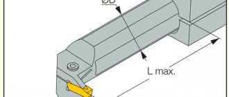
Type 1
1
- holder;
2
— cutting plate according to GOST 19062-80;
3
— support plate according to GOST 19079-80;
4
- sticking;
5
- screw;
6
— pin Fig.1
Marking
The marking describes the main mechanical and physical parameters of the tool. For example, 2130-0255 VK6 GOST 18884-73 says that this is a groove cutter, corresponds to GOST 18884-73, right-handed in version 1, with a cross-section of 25X16 mm and a plate made of VK6 hard alloy. Unlike a conventional cutting cutter according to GOST, the groove cutter is distinguished by the presence of a plate with VK6.
The cutting cutter according to GOST 18884-82 has an even more high-strength plate made from VK8 alloy or harder. Such tools can be used in automatic mode. You can select a product with the required parameters using the appropriate reference books.
Damn.3. Type 3
Type 3
1
- holder;
2
— cutting plate according to GOST 19046-80;
3
— support plate according to GOST 19073-80;
4
- wedge;
5
- screw;
6
— pin Drawing 3
Table 3
| mm | ||||||||||
| Right incisors | Left incisors | Cutter section | Pos.2 . Cutting insert according to GOST 19046-80 Col. 1 | Pos.3 . Support plate according to GOST 19073-80 Col. 1 | ||||||
| Designation | Applicability | Designation | Applicability | |||||||
| Designation | ||||||||||
| 2103-0671 | 2103-0672 | 16×16 | 16 | 19 | 20 | 125 | 01114-160304 | 701-1604 | ||
| 2103-0673 | 2103-0674 | 01114-160308 | ||||||||
| 2103-0675 | 2103-0676 | 01114-160312 | ||||||||
| 2103-0677 | 2103-0678 | 01114-160408 | 701-1603 | |||||||
| 2103-0681 | 2103-0682 | 01114-160412 | ||||||||
| 2103-0695 | 2103-0696 | 20×20 | 20 | 24 | 25 | 150 | 01114-220408 | 701-2204 | ||
| 2103-0697 | 2103-0698 | 01114-220412 | ||||||||
| 2103-0701 | 2103-0702 | 01114-220416 | ||||||||
| 2103-0711 | 2103-0712 | 25×25 | 25 | 29 | 32 | 01114-220408 | ||||
| 2103-0713 | 2103-0714 | 01114-220412 | ||||||||
| 2103-0715 | 2103-0716 | 01114-220416 | ||||||||
| 2103-0717 | 2103-0718 | 32×25 | 32 | 36 | 170 | 01114-220408 | ||||
| 2103-0721 | 2103-0722 | 01114-220412 | ||||||||
| 2103-0723 | 2103-0724 | 01114-220416 | ||||||||
| 2103-0725 | 2103-0726 | 32×32 | 40 | 01114-270612 | 701-2704 | |||||
| 2103-0727 | 2103-0728 | 01114-270616 | ||||||||
| 2103-0731 | 2103-0732 | 40×32 | 40 | 44 | 200 | 01114-270612 | ||||
| 2103-0733 | 2103-0734 | 01114-270616 | ||||||||
An example of a symbol for a type 3 cutter, cross-section = 25×25 mm, length = 150 mm, equipped with a cutting insert 01114-220412, right:
Cutter 2103-0713 GOST 20872-80
Recommendations for selecting a cutter
When choosing a tool, you must be guided by the functional purpose of the cutters. As for the material, sharpening angles and other parameters, it is necessary to take into account the hardness of the material of the workpiece being processed. It is also necessary to decide what is the most priority factor when carrying out work - quality, productivity, tool life.
The recommended minimum set of cutters consists of:
- Passage necessary for end processing;
- Outer neutral;
- Boring.
This basic set is sufficient to perform most standard operations, but of course, for more complex work you will need an expanded set of tools, including shaped and threaded cutters. For large-scale professional work, a reasonable option would be to purchase a set of cutters with replaceable inserts. This will allow you to subsequently spend less money on the purchase of consumables, as they wear out, only replacing the plates, and not the entire cutters.
Classification of cutters for turning
The classification of turning tools is regulated by the requirements of the relevant GOST. According to the provisions of this document, cutters are classified into one of the following categories:
- one-piece tool made entirely of alloy steel. There are also cutters that are made entirely of tool steel, but they are used extremely rarely;
- cutters, onto the working part of which a plate made of hard alloy is soldered. Instruments of this type are most widespread;
- cutters with removable carbide plates, which are attached to their working head using special screws or clamps. Cutters of this type are used much less frequently compared to instruments of other categories.
Classification of incisors
We will analyze the main features by which metal turning tools for manually controlled machines, semi-automatic and CNC automatic machines are classified.
Working part material
Cutter heads for metal lathes are made from materials with high hardness and wear resistance.
Tool high-speed steels
The main alloying element in such alloys is tungsten (P9, P18). Some grades of high-speed steels also contain molybdenum (P6M5) and cobalt (P6M5K5). Monolithic cutters are mainly made from these relatively inexpensive alloys. They are used for processing workpieces made of ordinary non-hardened steels, non-ferrous materials and their alloys.
One of the significant disadvantages of high-speed steels is a decrease in hardness when heated above 200 °C. Cutters quickly lose their properties when machining at high spindle speeds and feeds, with insufficient coolant supply.
Hard alloys
The basis of all hard alloys is carbides. Cobalt is used as a binder. Due to the high price, carbide is produced primarily in the form of plates, which are soldered or mechanically secured to cutter heads. There are also monolithic carbide tools (centering tools, drills) of small size.
Hard alloys are produced by sintering and hot pressing. They have high hardness (86 – 92 HRA) and red resistance (up to 1150 °C), therefore they are used for the manufacture of parts from difficult-to-cut materials: cast iron, stainless steel, heat-resistant, titanium-containing and hardened steels. Based on their chemical composition, hard alloys are divided into the following groups:
- Tungsten-cobalt (VK3, VK6, VK8).
- Titanium tungsten cotalt (T15K6, T5K10).
- Titanium-tantalum-tungsten-cobalt (TT7K12, TT20K9).
Due to the high cost of tungsten, tungsten-free hard alloys based on titanium carbides and cyanides were created. Carbide inserts with wear-resistant coatings are produced as a separate group of materials and have the letter marking VP.
Most foreign manufacturers of hard alloys use their own markings. Most often, it does not contain information about the composition of the material and coating, since this information is considered a trade secret. Instead, manufacturers provide clear recommendations for use.
Hard alloys have a number of limitations and disadvantages in comparison with high-speed steels: they are low-tech and have low impact strength (prone to cracking upon impact). To sharpen metal turning tools with carbide tips, a specialized abrasive tool (mostly diamond) is used.
Processing quality
Some sources suggest dividing cutters into rough, semi-finish and finishing. In fact, the quality of processing (surface roughness) depends not only on the design features of the cutting tool, but also on the quality of its sharpening and the processing mode - feed per revolution and allowance. Therefore, the same cutter can be used for both roughing and finishing turning operations.
Types of incisors according to operations performed
Screw-cutting lathes are capable of performing many types of processing and can be used to produce parts of different shapes. Depending on the purpose (operation performed), cutters for them are divided into several types:
- Pass-throughs are used for processing external surfaces of cylindrical and conical shapes, forming chamfers. Feeding is performed parallel to the workpiece axis.
- Scoring machines are used for trimming parts. The cutter is fed perpendicular to the axis of the workpiece.
- Passing thrust cutters perform all of the above operations. They are widely used in the manufacture of stepped shafts.
- Boring cutters are used for processing internal cylindrical and conical surfaces. One of the features of their design is a massive holder. Dimensional accuracy depends on the rigidity of this element.
- Threaded (external and internal) cutters are used for cutting metric and pipe threads. Their sharpening angles are 60° and 55°, respectively. For persistent and trapezoidal threads, specialized shaped cutters are used.
- Cutting machines are used for cutting workpieces.
- Slotting (groove) cutters are used for turning external and internal grooves (for the exit of the grinding wheel, for installing retaining rings, etc.)
- Shaped – highly specialized tools of various shapes for creating profile surfaces.
- Cutters for contour turning. This type of tool appeared relatively recently and is used mainly on CNC machines for finishing complex surfaces. Such cutters are equipped with diamond-shaped plates, have an acute sharpening angle and are designed to work with small allowances (up to 2 mm).
USE CAUTION!
No doubt you've heard that a burr should not be used to shape the outside of bowls and plates.
The discussion of this point, as well as the change of name in the English-language literature, arose in connection with the increase in the number of wood turners who believed that a roughing cutter would be a good idea to use for rough processing of bowls and plates. This caused numerous accidents.
And that's why this happens.
Firstly, when turning at centers, the fibers are oriented parallel to the axis. For the most part, wood is removed by cutting perpendicular to the grain. However, a traditional bowl has two areas where the wood grains are oriented perpendicular to the surface, i.e. the ends. The ends are much more difficult to process than the cross grains. Therefore, sharp jumps in cutting force occur at the time of processing.
You should also be careful when handling workpieces that contain knots. Essentially, these are the same end fibers
That’s why I recommended that for your first training in turning you choose a workpiece without knots (Fig. 15).
Rice. 15. Blanks for turning in centers and frontal turning (bowls)
Secondly, the design of the wide rail is such that its profile is made by bending a flat blank, and not by milling from a round rod, and has a thin shank that is inserted into the handle. The joint between the shank and handle of the tool (Fig. 16) is the weak link of the tool: it is not as strong as that of a bowl cutter, where a round bar is inserted into the handle (Fig. 17).
Rice. 16. Place of insertion into the handle of the wide rail
Rice. 17. Place of insertion into the handle of the cutter for bowls
Now you understand that when you process a bowl blank with a roughing cutter, the cutting edge collides with the end grain twice per revolution. Making a heavy cut or, worse, knocking off the corners left by the chainsaw, the tool takes a lot of hits and can break where the shank enters the handle.
Unfortunately, the trajectory of a cutter fragment can be unpredictable, and the consequences are sad.
Lathe cutter design
The structural elements of a turning tool are the cutting part or head and the holder, with the help of which the equipment is fixed in the tool holder of the machine. The cutter and holder can be square or rectangular. The cutter size must correspond to the standard range ranging from 160x100 to 630x500 mm for a rectangular configuration and from 40x40 to 400x400 mm for a square one.
The main working part of the cutter is the head, the cutting properties of which determine the angles of the edges. It is the angles of the turning cutter that determine the nature of metal removal from the workpiece. Basic angles:
- Main rear - located between the cutting planes and the rear surface of the cutter. The friction force parameter, the quality of processing and the wear rate of the tool depend on it. Selected according to the density of the material being processed.
- Main front - determines the level of deformation of the material during cutting, the cutting force and the efficiency of heat removal. It should be inversely proportional to the hardness of the material being processed - the higher it is, the smaller the angle.
- Cutting. Located between the front and back surfaces of the head.
- Points. Located between the front and back surfaces. The strength and sharpness of the equipment depends on it.
- Basic in plan. The amount of material removed depends on it.
- Secondary in plan. The roughness depends on it. The lower it is, the higher the quality of the surface.
- The vertex between the back auxiliary surface and the cutting edge. It has a direct correlation with the strength indicator.
- Inclination of the cutting edge - determines the geometry of the contact patch between the cutter and the surface of the part.
- Rear auxiliary - determines the friction between the rear plane and the workpiece.
All structural elements of a turning cutter are made from the same grade of steel. Metal-ceramic hard alloys T5K10 or similar are recommended.
How to make a cutter with your own hands for a wood lathe
Many carpenters prefer homemade wood turning tools. Therefore, they often make tools themselves rather than purchasing factory products. Of course, a tool manufactured in a factory meets all standards, since its production complies with technical specifications and occupational safety requirements, however, with the right approach, you can make cutters that are in no way inferior to branded ones.
The main difficulty in the initial stage of manufacturing is the correct selection of blanks.
In addition to how hard the cutting edge should be, it is important to consider the method of attaching the tool to the holder. Thanks to this component, the tool is fixed
In this regard, it is important to consider the importance of overall dimensions.
The next point is the selection of procurement materials. Ideally, it is best to use tool steel blanks, but the disadvantage for processing them in home workshops is the hardness of the material. Because of this, a number of improvised materials are mainly used, which are hardened after preliminary treatments.
According to many professional home craftsmen, to make a high-quality cutter with your own hands, you can use the following blanks:
rasps or files. Often processing is carried out with already worn tools that have lost their original condition.
It is important to check before this that there are no cracks or significant chips on the material; steel reinforcing bars. Craftsmen recommend using models with a square cross-section and original dimensions that do not differ much from the factory ones; car springs
The main difficulty is primary processing, since the workpiece will need to be given a rectangular shape using an autogen or welding machine.
After the desired shape has been ensured for the future tool, its initial sharpening is performed. After sharpening, the cutting edge is hardened. To carry out this operation, the edge of the cutter must be heated to a glowing temperature (reddening of the metal), then cooled in machine oil, and lower the cutter there.
In the process of making cutting tools yourself, it is important to know:
- that with a smaller size of the working part, it is much more difficult and problematic to hold it during the turning process. The length of the size should be ensured by a full grip with the hand, plus stops on the armrests, plus distances from the armrests to the workpieces, plus reserves for wear and sharpening. Therefore, the initial length of the working parts should be at least 200 mm, but dimensions exceeding 400 mm cause inconvenience in the work process. The optimal length is considered to be 200-300 mm;
- The shorter the tang size, the more likely it is to be pulled out of the handle. Based on this, when manufacturing a cutting tool made from a file or rasp, the size of the shank is lengthened by at least 1.5 times;
- The thinner and narrower the working part of the tool, the more likely it is to be damaged when processing the workpiece during turning. Because of this, at the initial stage of turning, when the workpiece does not have an absolute cylindrical shape and runout occurs on the surface of the blade, as well as with a large diameter, when the cutting force has large values, cutters with a sufficient thickness should be used.
- A wood turning tool must be equipped with a handle that is at least 250 mm. If its dimensions are significantly smaller, then during turning the cutter will be difficult to hold in the hand, which will lead to poor processing quality.
To prevent possible dangerous situations, you need to check the quality of work using homemade tools on soft wood. After grinding a small part of the workpiece, you need to check how much the original geometry of the cutter has been preserved.
Contour turning cutters.
| Cutting insert grade – Composite 09 PTNB. Used for finishing turning of HRC 55…65 steels. |
| Designation | Dimensions , mm | Cutting insert | Weight, kg | |||||||
| Right | Left | λ° | γ° | h | b | L | h1 | f | ||
| 2102-4052К MCLNR 2022 K12 | 2102-4052К -01 MCLNL 2022 K12 | -6 | -6 | 20 | 20 | 125 | 20 | 25 | CNMM-120408 PNTB | 0,9 |
| -02 MCLNR 2525 M12 | -03 MCLNL 2022 M12 | 25 | 25 | 150 | 25 | 32 | 1,3 | |||
| -04 MCLNR 3232 P12 | -05 MCLNL 3232 P12 | 32 | 32 | 170 | 32 | 40 | 1,8 | |||
The difference between modern Composite 09 PTNB is the absence of impurities and high dispersion of the material, produced in two modifications: PTNB-micro grain size 1.0 microns; PTNB - nano grain size 0.1 microns. New tools provide a 5-10-fold increase in processing productivity for hard-to-cut materials, processing accuracy up to 0.5 microns and surface finish up to Ra 0.1 microns without subsequent grinding and finishing operations. The performance characteristics of OJSC OIZ tools are not inferior to similar tools from foreign companies, since they are equipped with composites of significantly finer grain size, which contain less binder fraction and, accordingly, higher physical and mechanical properties. By special order it is possible to produce plates of any other shapes. equipped with composites based on cubic boron nitride and polycrystalline diamond.
General rules and safety precautions
Principles of safe work on a wood lathe:
- You should work in special clothing, which must be put on before turning on the machine;
- there should be no unnecessary objects or tools on the machine;
- be sure to check the workpiece for knots and cracks;
- check the serviceability of the cutting tool and its sharpness;
- wear safety glasses;
- when working, apply the cutter to the part only when the shaft reaches full rotation speed;
- do not tilt your head close to the machine;
- take measurements of the part only after stopping rotation;
- You must not leave the machine while it is working.
After work, it is recommended to remove chips with a special brush.
When working on a wood lathe, you need a whole set of different cutters. Each of them performs its own function and is designed for a specific job. Such cutters can be purchased in stores or made independently.
Lathe boring cutters.
Designed for boring through and blind holes on boring machines and CNC lathes. Fastening system - S (screw). Used for semi-finish and fine boring.
Boring cutters
for blind holes.
| Designation | d | h | h1 | f | L | l | Cutting inserts | Weight, kg | |
| Right | Left | ||||||||
| 2140-4059 S20Q SCLCR09 | — | 20 | 19 | 9 | 13 | 180 | 8 | 05229-09T308 CCMT-09T308 | 0,425 |
| 2140-4061-00 S25T SCLCR12 | 2140-4061-01 S25T SCLCL12 | 25 | 23 | 11,5 | 17 | 300 | 6 | 05229-120408 CCMT-120408 | 1,57 |
| 2140-4061-02 S32U SCLCR12 | 2140-4061-03 S32U SCLCL12 | 32 | 30 | 15 | 22 | 350 | 10 | 2,06 | |
Boring cutters for through holes.
| Designation | d | h | h1 | f | L | l | Cutting inserts | Weight, kg | |
| 2140-4060 S20Q SSKCR | 20 | 19 | 13 | 13 | 180 | 6 | 03229-09T308 SCMT-09T308 | ||
The cutters in the basic version are supplied with a cutting insert manufactured by Sandvik. * The grade of carbide, the number of cutting inserts and the manufacturer of the cutting inserts are specified when ordering.
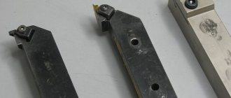
Fastening the cutting elements of the cutter
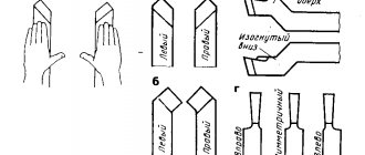
The cutting inserts are connected to the cutter head by soldering, welding or mechanically. In the first two cases, a groove of one shape or another is pre-milled on the cutter head: open, semi-closed, closed (Fig. 5). However, when brazing, carbide inserts are exposed to temperature changes, which causes microcracks to appear and cutters to fail. The best option for securing the plates is their mechanical fastening.
Rice. 5. Shapes of grooves for the plate
- a – groove at the front angle;
- b – regrinding diagram with a plate in a closed groove;
- c – open groove;
- g – semi-closed groove;
- d – closed groove
In Fig. Figure 6 shows some diagrams for fastening carbide inserts with a hole. Steel pin 1 is pressed into the holder (Fig. 6, a), and plate 3 is put on it. Double-sided wedge 4, when screwing in screw 5, presses the plate to the pin and. thus securing it. More successful, due to the reduction in the number of joints, is the design in Fig. 6, b, where by turning the axis 6 with the eccentric, the plate is pressed against the base ledge of the holder 2. Here, to ensure self-braking, high accuracy of the dimensional chain ledge - axis and eccentric - plate must be ensured.
Rice. 6. Methods for mechanical fastening of carbide inserts with a hole
In Fig. 6b shows a self-braking design that allows for greater clamping force. Clamping plate 3 in the design in Fig. 6, g is carried out by rod 7, moved by spring 8.
In the above designs, the forces acting during cutting improve the fastening of the plates. During the cutting process, the plate gradually crushes the supporting surface of the socket, which leads to the formation of a gap, the occurrence of variable loads and breakage of the plate. Therefore, in modern designs, the bearing surface of the socket is protected by a hardened steel or carbide gasket 9 (Fig. 6, a) of the same configuration as the cutting plate.
In addition to turning cutters, lathe machines use axial cutting tools for machining holes: drills, countersinks, reamers, taps, as well as dies for cutting external threads.
The cutters on lathes and screw-cutting lathes are fixed in the tool holder, the axial tool is fixed in the conical boring of the tailstock quill using auxiliary mandrels, chucks, etc.
On turret lathes, cutters and axial tools are secured in the sockets of the turret head also with the help of auxiliary equipment. On rotary lathes, all the mentioned methods of securing a tool are used.
Damn.2. Type 2
Type 2
1
- holder;
2
— cutting plate according to GOST 19062-80;
3
— support plate according to GOST 19079-80;
4
- sticking;
5
- screw;
6
— pin Fig.2
Table 1
| mm | ||||||||||||
| Right incisors | Left incisors | Cutter section | Pos.2 . Cutting insert according to GOST 19062-80 Col. 1 | Pos.3 . Support plate according to GOST 19079-80 Col. 1 | ||||||||
| Designation | Applicability | Designation | Applicability | Right | Left | Right | Left | |||||
| Designation | ||||||||||||
| 2101-0601 | 2101-0602 | 20×20 | 20 | 27 | 25 | 150 | 08116-170405-130 | 08116-170405-230 | 741-1704-1 | 741-1704-2 | ||
| 2101-0603 | 2101-0604 | 08116-170410-130 | 08116-170410-230 | |||||||||
| 2101-0605 | 2101-0606 | 08116-170410-136 | 08116-170410-236 | |||||||||
| 2101-0607 | 2101-0608 | 08116-170415-130 | 08116-170415-230 | |||||||||
| 2101-0611 | 2101-0612 | 08116-170415-136 | 08116-170415-236 | |||||||||
| 2101-0637 | 2101-0638 | 25×25 | 25 | 32 | 32 | 08116-190605-130 | 08116-190605-230 | 741-1904-1 | 741-1904-2 | |||
| 2101-0641 | 2101-0642 | 08116-190610-130 | 08116-190610-230 | |||||||||
| 2101-0643 | 2101-0644 | 08116-190610-136 | 08116-190610-236 | |||||||||
| 2101-0645 | 2101-0646 | 08116-190615-130 | 08116-190615-230 | |||||||||
| 2101-0647 | 2101-0648 | 08116-190615-136 | 08116-190615-236 | |||||||||
| 2101-0651 | 2101-0652 | 32×25 | 32 | 39 | 170 | 08116-190605-130 | 08116-190605-230 | |||||
| 2101-0653 | 2101-0654 | 08116-190610-130 | 08116-190610-230 | |||||||||
| 2101-0655 | 2101-0656 | 08116-190610-136 | 08116-190610-236 | |||||||||
| 2101-0657 | 2101-0658 | 08116-190615-130 | 08116-190615-230 | |||||||||
| 2101-0661 | 2101-0662 | 08116-190615-136 | 08116-190615-236 | |||||||||
| 2101-0663 | 2101-0664 | 32×32 | 40 | 08116-190605-130 | 08116-190605-230 | |||||||
| 2101-0665 | 2101-0666 | 08116-190610-130 | 08116-190610-230 | |||||||||
| 2101-0667 | 2101-0668 | 08116-190610-136 | 08116-190610-236 | |||||||||
| 2101-0671 | 2101-0672 | 08116-190615-130 | 08116-190615-230 | |||||||||
| 2101-0673 | 2101-0674 | 08116-190615-136 | 08116-190615-236 | |||||||||
| 2101-0675 | 2101-0676 | 40×32 | 40 | 47 | 200 | 08116-190605-130 | 08116-190605-230 | |||||
| 2101-0677 | 2101-0678 | 08116-190610-130 | 08116-190610-230 | |||||||||
| 2101-0681 | 2101-0682 | 08116-190610-136 | 08116-190610-236 | |||||||||
| 2101-0683 | 2101-0684 | 08116-190615-130 | 08116-190615-230 | |||||||||
| 2101-0685 | 2101-0686 | 08116-190615-136 | 08116-190615-236 | |||||||||
An example of a symbol for a type 1 cutter, cross-section = 25×25 mm, length = 150 mm, equipped with a cutting insert 08116-190610-130, right:
Cutter 2101-0641 GOST 20872-80
table 2
| mm | ||||||||||||
| Right incisors | Left incisors | Cutter section | Pos.2 . Cutting insert according to GOST 19062-80 Col. 1 | Pos.3 . Support plate according to GOST 19079-80 Col. 1 | ||||||||
| Designation | Applicability | Designation | Applicability | Right | Left | Right | Left | |||||
| Designation | ||||||||||||
| 2101-0757 | 2101-0758 | 20×20 | 20 | 27 | 25 | 150 | 08116-170405-130 | 08116-170405-230 | 741-1704-1 | 741-1704-2 | ||
| 2101-0761 | 2101-0762 | 08116-170410-130 | 08116-170410-230 | |||||||||
| 2101-0763 | 2101-0764 | 08116-170410-136 | 08116-170410-236 | |||||||||
| 2101-0765 | 2101-0766 | 08116-170415-130 | 08116-170415-230 | |||||||||
| 2101-0767 | 2101-0768 | 08116-170415-136 | 08116-170415-236 | |||||||||
| 2101-0795 | 2101-0796 | 25×25 | 25 | 32 | 27 | 08116-190605-130 | 08116-190605-230 | 741-1904-1 | 741-1904-2 | |||
| 2101-0797 | 2101-0798 | 08116-190610-130 | 08116-190610-230 | |||||||||
| 2101-0801 | 2101-0802 | 08116-190610-136 | 08116-190610-236 | |||||||||
| 2101-0803 | 2101-0804 | 08116-190615-130 | 08116-190615-230 | |||||||||
| 2101-0805 | 2101-0806 | 08116-190615-136 | 08116-190615-230 | |||||||||
| 2101-0807 | 2101-0808 | 32×25 | 32 | 39 | 170 | 08116-190605-130 | 08116-190605-230 | |||||
| 2101-0811 | 2101-0812 | 08116-190610-130 | 08116-190610-230 | |||||||||
| 2101-0813 | 2101-0814 | 08116-190610-136 | 08116-190610-230 | |||||||||
| 2101-0815 | 2101-0816 | 08116-190615-130 | 08116-190615-230 | |||||||||
| 2101-0817 | 2101-0813 | 08116-190615-136 | 08116-190615-236 | |||||||||
| 2101-0821 | 2101-0822 | 32×32 | 32 | 08116-190605-130 | 08116-190605-230 | |||||||
| 2101-0823 | 2101-0824 | 08116-190610-130 | 08116-190610-230 | |||||||||
| 2101-0825 | 2101-0826 | 08116-190610-136 | 08116-190610-230 | |||||||||
| 2101-0827 | 2101-0828 | 08116-190615-130 | 08116-190615-230 | |||||||||
| 2101-0831 | 2101-0832 | 08116-190615-136 | 08116-190615-236 | |||||||||
| 2101-0833 | 2101-0834 | 40×32 | 40 | 47 | 200 | 08116-190605-130 | 08116-190605-230 | |||||
| 2101-0835 | 2101-0836 | 08116-190610-130 | 08116-190610-230 | |||||||||
| 2101-0837 | 2101-0838 | 08116-190610-136 | 08116-190610-236 | |||||||||
| 2101-0841 | 2101-0842 | 08116-190615-130 | 08116-190615-230 | |||||||||
| 2101-0843 | 2101-0844 | 08116-190615-136 | 08116-190615-236 | |||||||||
An example of a symbol for a type 2 cutter, cross-section = 25×25 mm, length = 150 mm, equipped with a cutting insert 08116-190610-130, right:
Cutter 2101-0797 GOST 20872-80
How to install on the machine
To obtain the proper quality and precision of processing, correct installation of the cutter is necessary. Also, installation errors contribute to rapid wear of the cutting edge.
The tool is installed in the tool holder strictly in the center. To adjust it in height, the turner must have metal plates with a thickness of 1 to 4-5 mm in his arsenal. Setting below center causes the part to be pushed out, which is dangerous for both the tool and the worker. If the cutting edge is too high, it overheats and wears out quickly.
When installing a cutting tool, you need to follow simple rules:
- Wipe the supporting surface of the tool holder.
- Secure the tool with at least two bolts.
- The overhang of the head should not exceed 1.5 times the height of the holder.
- When roughing, it is allowed to overestimate the cutting edge by 0.3-1 mm.
After installing the tool, you need to remove test chips. If the surface is flat and smooth, the chips do not wrap around the cutter, you can start working.
Important!
Do not use more than three gaskets. Also, they should not protrude beyond the tool holder.
Turning cutters through passage.
Used for semi-finish and finishing turning. The plate fastening system is P (lever).
| Designation | h = h 1 | b | f | L | Cutting inserts | Weight, kg | |
| Right | Left | ||||||
| 2102-4036 PSSNR2525M12 | 2102-4036-01 PSSNL2525M12 | 25 | 25 | 32 | 158,3 | 03123-120412 SNMA-120412 | 0,96 |
| -02 PSSNR3225P15 | -03 PSSNL3225P15 | 32 | 180,2 | 03124-150612 SNMM-150612 | 1,08 | ||
| Designation | h = h 1 | b | f | L | Cutting inserts | Weight, kg | |
| Right | Left | ||||||
| 2102-4035 PCLNR2525M16 | 2102-4035-01 PCLNL2525M16 | 25 | 25 | 32 | 150 | 05124-160412 CNMM-160412 | 0,72 |
| -02 PCLNR3225P16 | -03 PCLNL3225P16 | 32 | 170 | 1,06 | |||
| Designation | h = h 1 | b | f | f1 | l | L | Cutting inserts | Weight, kg | |
| Right | Left | ||||||||
| 2109-4009 PTFNR2525M16 | 2109-4009-01 PTFNL2525M16 | 25 | 25 | 32 | 17,4 | 20,2 | 150 | 01124-160408 TNMM-160408 | 1,43 |
| -02 PTFNR2525M22 | -03 PTFNL2525M22 | 24,4 | 25,2 | 01124-220408 TNMM-220408 | 1,57 | ||||
| -04 PTFNR3225P22 | -05 PTFNL3225P22 | 32 | 170 | 2,75 | |||||
Various options and their purpose
The variety of cutting tools for wood when rotating on a lathe is very large. Experienced craftsmen create cutters of the shape they consider convenient for the implementation of individual tasks. Therefore, one personal cutter is not similar to another. However, there are standards for factory tools, some of which are basic, others highly specialized.
Reyer
This is one of the basic incisors. It can be recognized by its characteristic shape - the working part of the rail is not flat, but curved, forming a groove. Sharpening is done from the inside of the curve. They work with a rake, bringing it to the workpiece with the groove up.
Thanks to the shape of the blade, this cutter selects wood in a semicircle. Its longitudinally curved shape makes it very durable, making it well suited for rough turning of workpieces. With the help of a reyer you can also make smooth transitions and grooves with a semicircular profile.
Expert opinion Dmitry Konstantinovich Levin
The width of the rib ranges from 4 to 30 mm, and the sharpening angle is about 30 degrees.
Meysel
If a reyer is a relatively simple tool, which is intended primarily for rough, rough work, then a meisel is already much more difficult to use. It is unlikely that you will be able to master it in a couple of days of practice. This cutter is used already when the outlines of the wooden product are formed. However, for an experienced turner, the use of a meisel gives an even, smooth surface of wood of a given geometry.
The Meisel is a bit like a regular flat hammer chisel, but its blade is angled. Accordingly, the master must have at his disposal at least two meisels - left- and right-handed - in order to process mirrored areas.
Sharpening the meisel can be done either by beveling one side until it comes out flat, or by equally removing the metal layer from both sides. In this case, the width of the blade can reach up to 40 mm, and the bevel angle ranges from 60 to 75 degrees. When sharpening a cutting edge on both sides, the angle should be 20 – 25° on each side.
Shaped
After the main processing of the part in the headstocks has been completed, it is the turn of the figured cut. For this purpose, shaped cutters are used. They can have different shapes for turning grooves, grooves, and select grooves of complex shapes.
Klukarza.
The most common “styles” are:
- Klukarza. The shape of the cutter is similar to the reyer, but has a bend in the working part near the blade. Thanks to this shape, the cranberry can be used for small and complex work; it can reach places where tools with a straight working part cannot reach.
- Comb. It makes parallel grooves and grooves. With the proper level of skill, a thread is cut using a comb.
- Hook. Allows you to make an internal recess with a protruding edge, as well as various curved grooves.
- Crescent or dovetail. Used for turning round and faceted beads.
The process of turning a workpiece on a lathe significantly depends on the sharpening angle of the tool. Small angles (20 – 30°) are intended for fine work
They remove wood well, but if moved carelessly they can damage the workpiece or break themselves. Large angles (60 – 75°) are designed for rough work in hard rocks
They can remove less in one pass, but they are not afraid of knots and pressure created by the turner.
Manufacturers
When choosing cutters, you should focus not on the best price, but on the product’s compliance with the requirements of the state standard. Cutters produced according to technical specifications are unlikely to last long, and sharpening them will be problematic. Non-compliance with the standard directly indicates a change in the composition of materials towards cheaper prices. For example, for the VK8 alloy, a difference of a few percent of cobalt radically changes the strength and temperature characteristics.
Only products manufactured in accordance with GOST can provide the declared parameters and ensure an uninterrupted technological cycle.
Damn.4. Type 4
Type 4
1
- holder;
2
— cutting plate according to GOST 19046-80;
3
— support plate according to GOST 19073-80;
4
- wedge;
5
- screw;
6
— pin Fig.4
Table 4
| mm | ||||||||||
| Right incisors | Left incisors | Cutter section | Pos.2 . Cutting insert according to GOST 19046-80 Col. 1 | Pos.3 . Support plate according to GOST 19073-80 Col. 1 | ||||||
| Designation | Applicability | Designation | Applicability | |||||||
| Designation | ||||||||||
| 2101-0915 | 2101-0916 | 16×16 | 16 | 19 | 9 | 125 | 01114-160304 | 701-1604 | ||
| 2101-0917 | 2101-0918 | 01114-160308 | ||||||||
| 2101-0921 | 2101-0922 | 01114-160312 | ||||||||
| 2101-0923 | 2101-0924 | 01114-160408 | 701-1603 | |||||||
| 2101-0925 | 2101-0926 | 01114-160412 | ||||||||
| 2101-0941 | 2101-0942 | 20×20 | 20 | 24 | 11 | 150 | 01114-220408 | 701-2204 | ||
| 2101-0943 | 2101-0944 | 01114-220412 | ||||||||
| 2101-0945 | 2101-0946 | 01114-220416 | ||||||||
| 2101-0955 | 2101-0956 | 25×25 | 25 | 29 | 15 | 01114-220408 | ||||
| 2101-0957 | 2101-0958 | 01114-220412 | ||||||||
| 2101-0961 | 2101-0962 | 01114-220416 | ||||||||
| 2101-0963 | 2101-0964 | 32×25 | 32 | 36 | 170 | 01114-220408 | ||||
| 2101-0965 | 2101-0966 | 01114-220412 | ||||||||
| 2101-0967 | 2101-0968 | 01114-220416 | ||||||||
| 2101-0971 | 2101-0972 | 32×32 | 01114-270612 | 701-2704 | ||||||
| 2101-0973 | 2101-0974 | 01114-270616 | ||||||||
| 2101-0975 | 2101-0976 | 40×32 | 40 | 44 | 200 | 01114-270612 | ||||
| 2101-0977 | 2101-0978 | 01114-270616 | ||||||||
An example of a symbol for a type 4 cutter, cross-section =25×25 mm, =150 mm, equipped with a cutting insert 01114-220412, right:
Cutter 2101-0957 GOST 20872-80
4. The geometric parameters of the cutters and the design of their parts are given in the Appendix.
5. Technical requirements - according to GOST 26613-85.
Geometric parameters and tool dimensions
- Geometry of the body or holder: L – length of the body, B and H – dimensions of the cross-sectional sides.
- Shape of the working cutting plate: l – length of the working part of the cutter, b – height of the plate body, S – thickness.
- Location of the cutting element in the body. The socket for the plate can occupy the entire width of the case or one of the corners. In the latter case, the width of the socket is indicated by the letter n. The plate can be placed in the socket at a certain angle to the body.
The blade for cutting the workpiece also has its own parameters, expressed in angles.
- “Gamma” displays the front sharpening angle - this is the main element of the cutting edge.
- “Alpha” is the rear main sharpening angle.
- “Alpha” with index 1 is the rear corner for auxiliary purposes.
- "Lambda" is the angle at which the cutting edge is inclined.
- “Phi” is the main purpose angle located in plan.
- “Phi” with index 1 is an auxiliary angle located in plan.
Features of product geometry
The geometry of a shaped cutter depends on its design, which in turn depends on the size and profile of the part. The main ones are cutting angles, sharpening, the main front and back, and also for some products additional angles are introduced into the design. The parameters can be very different. Proper design of the tool shape and the correct selection of the grade of steel/steels for its manufacture will help to obtain a high-quality part from a workpiece. The profile of a future product is calculated by specialists in 2 ways: analytical and graphical, each of which requires certain skills and the ability to use specific reference books and literature
Work experience is also important
Features of using a groove cutter
Cutting workpieces on turning equipment occurs in compliance with certain modes. Thus, the groove type of cutters requires a different application than other types of cutting equipment. If we take depth processing, then in one feed they do not go deeper than the width of the edge. The expansion of the groove occurs through several passes of the tool along the axis of the part. The feed speed is influenced by many factors: the material being processed and the type of cutting equipment, so there are limits from 0.2 to 0.07 millimeters per revolution.
The grooves that can be produced on the surface of the workpiece are of different types.
- Narrow in width, where the size is equal to the size of the working part of the cutter. This processing is carried out manually and only one pass is used here. The tool is fed precisely to the location of the future recess according to the drawing.
- Grooves formed on the ledges of a part or its ends. In this case, a dial is used to feed in the transverse direction - this is how the diameter of the future recess is set, and the required depth is achieved using the dial for moving the caliper in the longitudinal direction.
- Wide-sized recesses. They are obtained in several passes. First, the groove cutter is fed to the required depth (taking into account 0.5 millimeters of allowance) from the right side of the groove. The allowance is left in order to do the finishing at the final stage. Then, moving from right to left, they reach the other end of the groove. Next, the part is cut clean in the opposite direction.
Groove turning cutters.
| The cutter is used for internal contour boring and cutting internal grooves. Right. Drawing 2130-4120. Designation S32S-CSFCR 5. Left. Drawing 2130-4020-01. Designation S32S-CSFCL 5. Insert TGMF 508 IC908 “Iscar”. Weight 1.5 kg. |
| Used for cutting internal grooves and shaped turning. Cutting insert TSC 4 TT7220 "Taegu Tec". |
| According to drawing / Designation | Dimensions , mm | Weight, kg | ||||||||
| Right | Left | d | L | H | H1 | H2 | Dmn | B | W | |
| 2130-4021 S25R-CSFCR3 | 2130-4021-01 S25R-CSFCL3 | 25 | 200 | 11,5 | 30,7 | 23 | 38 | 38 | 2,65; 3; 3,15 | 1,1 |
| -02 S32S-CSFCR3 | -03 S32S-CSFCL3 | 32 | 250 | 15 | 34,2 | 30 | 42 | 41,5 | 1,5 | |
| -04 S25R-CSFCR4 | -05 S25R-CSFCL4 | 25 | 200 | 11,5 | 30,7 | 23 | 38 | 38 | 4; 4,15 | 1,1 |
| -06 S32S-CSFCR4 | -07 S32S-CSFCL4 | 32 | 250 | 15 | 34,2 | 30 | 42 | 41,5 | 1,5 | |
Types
The basic classification of shaped cutters given below is based on the flank configuration and design features.
In addition, the taxonomy uses such parameters as:
- feed direction;
- position of the hole and mounting base;
- position of the front surface;
- shape of forming surfaces;
- design.
Rod
In design, shaped rod cutters are in many ways similar to turning ones, but differ in the edge corresponding to the configuration of the target surface of the workpiece. They are designed for short shaped surfaces and have a low working part height. This results in a small number of regrinds, which is the main disadvantage of rod cutters. Therefore, they are rarely used in production. They have a standard method of fastening in the machine support.
Round
Models with a round configuration perform rotation. To form the front surface and ensure chip flow, they have an angular groove. Due to the installation of the cutter axis above the workpiece axis, positive clearance angles are obtained at the edge. For options with an axis parallel to the axis of the workpiece, the edges are perpendicular to it, and their angles are equal to zero. The rear surface formed when the edge rotates relative to the tool axis is the end plane. When working, she comes into contact with the object. As a result, there is no gap between them, which reduces cutting ability. This is also typical for prismatic shaped cutters with standard installation. To form positive rear angles of the edges perpendicular to the axis of the workpiece, round cutters with an inclined axis relative to the object, as well as prismatic ones with an inclined mounting base, are used. Such options are capable of processing undercuts with inclined feed.
These tools are most suitable for creating stepped channels using axial feed. There may be a shank for installation.
Used for working with external and internal surfaces. They are distinguished by the largest number of sharpenings among all types of shaped cutters, therefore, this is the most technologically advanced option.
Disc models are easier to manufacture and can have many regrinds, but are characterized by lower fastening rigidity compared to prismatic ones. They are relevant for objects with a shallower profile depth.
Prismatic
Made in the configuration corresponding to the name. The side face with a cylindrical surface serves as the rear surface, and the flat end serves as the front surface. The back corners of the edge are created by inclined installation. Cutters of this type have many sharpenings. They are designed for processing complex, long shaped surfaces. Compared to round ones, they are distinguished by greater edge strength, a wider range of clearance angles, more reliable fastening, better heat dissipation, and greater accuracy of work. However, they are not suitable for internal processing.
Shaped cutters
- Home /
- Mechanical restoration /
- Shaped cutters
Shaped cutters are non-standard cutters.
Shaped cutters are used for processing parts with a complex generatrix shape. Compared to conventional cutters, they provide identical shape, dimensional accuracy of the part, which depends mainly on the manufacturing accuracy of the cutter, high productivity due to the simultaneous processing of all sections of the shaped profile of the part, and greater savings in machine time. Cutters are designed to process a specific part, and their use is economically justified in large-scale and mass production.
Rice. 1. Shapes of shaped cutters.
| A) | b) |
| V) |
Shaped cutters are classified according to the following criteria:
1. In shape - rod (Fig. 1, a), prismatic (Fig. 1, b) and round (Fig. 1, c).
- Rod cutters are used for processing short shaped surfaces. Their disadvantage is the small number of regrinds due to the low height of the working part.
- Prismatic shaped cutters have a greater number of grinds and can process longer shaped surfaces. Fastening and basing of the cutter in a special tool holder is carried out using a dovetail fastening. The disadvantage of prismatic cutters is the inability to process internal shaped surfaces.
- Round shaped cutters are used for processing both external and internal shaped surfaces. They are more technologically advanced than prismatic ones and allow a greater number of regrindings. The cutters are installed in a special tool holder and aligned along the hole and end.
2. In the direction of supply: radial (Fig. 2, a) and tangential (Fig. 2, b).
Rice. 2. Radial and tangential shaped cutters. Sr - radial feed of the cutter, St - tangential feed.
3. According to the location of the axis of the hole or the mounting base of the cutter in relation to the axis of rotation of the workpiece: with a parallel or inclined arrangement.
4. By design: solid and composite, for example, with soldered carbide plates.
Table 1
Geometric elements of the blade of the working part of shaped cutters
| Workpiece material | Front angle g, deg. | |
| BRS | TS | |
| Aluminum, copper | 20 — 25 | 10 — 15 |
| Bronze, lead brass | 0 — 10 | 0 — 5 |
| Steel with sv, MPa: | — | — |
| up to 500 | 25 | 20 |
| 500 — 800 | 20 — 25 | 15 — 20 |
| 800 — 1000 | 10 — 15 | 5 — 10 |
| Cast iron with NV: | — | — |
| up to 200 | 12 — 15 | 8 — 10 |
| over 200 | 8 | 8 |
| Rear angle, a | 8 — 15 | 8 — 12 |
| Note: BRS - high-speed steel, TS - carbide | ||
table 2
Dimensions of shaped disk cutters with holes for pins, mm.
| Workpiece profile depth, tmax, mm, no more | D | D (H8) | d1 | bmax | K | r | D1 | d2 |
| 6 | 50 | 13 | 20 | 9 | 3 | 1 | 28 | 5 |
| 8 | 60 | 16 | 25 | 11 | 3 | 2 | 34 | 5 |
| 11 | 75 | 22 | 34 | 15 | 4 | 2 | 42 | 5 |
| 14 | 90 | 22 | 34 | 18 | 4 | 2 | 45 | 6 |
| 18 | 100 | 27 | 40 | 23 | 5 | 2 | 52 | 8 |
| 25 | 125 | 27 | 40 | 30 | 5 | 3 | 55 | 8 |
Table 3
Dimensions of shaped disk cutters with end grooves, mm.
| Workpiece profile depth, tmax, mm, no more | D | D (H8) | d1 | bmax | K | r | D1 | d2 |
| 4 | 30 | 10 | 16 | 7 | 3 | 1 | — | — |
| 6 | 40 | 13 | 20 | 10 | 3 | 1 | 20 | 3 |
| 8 | 50 | 16 | 25 | 12 | 4 | 2 | 26 | 3 |
| 10 | 60 | 16 | 25 | 14 | 4 | 2 | 32 | 3 |
| 12 | 70 | 22 | 34 | 17 | 5 | 2 | 35 | 4 |
| 15 | 80 | 22 | 34 | 20 | 5 | 2 | 40 | 4 |
| 18 | 90 | 22 | 34 | 23 | 5 | 2 | 45 | 5 |
| 21 | 100 | 27 | 40 | 25 | 5 | 2 | 50 | 5 |
Notes:
- For a given profile depth tmax, it is allowed to use cutters with large overall dimensions, for example, for a workpiece with a profile depth of 7 mm, cutters with overall dimensions for tmax< 14 mm can be used.
- The rake angle g is selected according to the table. 1
- The size of Lp depends on the length of the surface being processed.
- Dimensions
| Rice. 3. Tool holder for round shaped cutter | Rice. 4. Tool holder for prismatic shaped cutter |
- Turning cutters
- Axial tool
Labeling and manufacturers
The description of groove turning tools will be incomplete without mentioning the markings, which determine the composition of the material of their cutting part. For example, the T5K10 cutter is made of a hard alloy of the titanium-tungsten group, which contains 5% titanium carbide and 10% cobalt. The markings of products made from other materials are deciphered in a similar way.
The most famous manufacturers of grooving turning tools are:
- Dnepropetrovsk industrial tools plant (Ukraine);
- (Ukraine);
- Zenitech company (Switzerland);
- Proma company (Czech Republic);
- Itertool company (China).