Buy GOST 26810-86 - a paper document with a hologram and blue seals. more details
We have been distributing regulatory documents since 1999. We punch checks, pay taxes, accept all legal forms of payment without additional interest. Our clients are protected by law. LLC "CNTI Normocontrol"
Our prices are lower than other places because we work directly with document providers.
Delivery methods
- Express courier delivery (1-3 days)
- Courier delivery (7 days)
- Pickup from the Moscow office
- Russian Post
Applies to metalworking and assembly non-mechanized metalworking tools manufactured for the needs of the national economy and for export.
The validity period has been lifted: Protocol No. 7-95 MGS dated 03/01/95 (IUS 11-95)
Table of contents
1. General Provisions
2 Control of the appearance and markings of instruments
3 Control of dimensional parameters and parameters characterizing the roughness of tool surfaces
4 Control of parameters characterizing coatings, hardness and strength of tools
5 Performance tests
| Date of introduction | 01.01.1987 |
| Added to the database | 01.09.2013 |
| Update | 01.01.2019 |
This GOST is located in:
- Ecology section
- Section 25 MECHANICAL ENGINEERING
- Section 25.140 Hand Tools
- Section 25.140.30 Hand Operated Instruments
- Electricity section
- Section 25 MECHANICAL ENGINEERING
- Section 25.140 Hand Tools
- Section 25.140.30 Hand Operated Instruments
Organizations:
| 27.01.1986 | Approved | USSR State Committee for Standards | 202 |
| Published | Publishing house of standards | 1994 | |
| Published | Publishing house of standards | 1986 |
Fittter tools. Acceptance rules
For free
download this document in PDF format, support our site and click the button:
How is scraping done?
The word “scraping” itself, which can be translated as “scraping”, came to us from Germany. It very accurately corresponds to the essence of the technological operation that it denotes. During this operation, irregularities are scraped off the surface of the part, which makes it as smooth as possible.
The scrapers used to perform this operation are made of tool steel. The design of this tool consists of a four- or triangular-shaped handle and a cutting part. To give the working part of the scraper the required degree of hardness (64–66 HRC units), it is subjected to hardening.
Doctors are made mainly of standard length (20–40 cm), and the width of their cutting edge depends on the type of operation being performed. Thus, rough scraping is performed with a tool whose working part width is 20–30 mm; for finishing scraping, this interval is 15–20 mm.
The type of scraping performed also influences the angle of the tip that should be formed on the tool. Plumbing experts recommend using the following sharpening angles for the cutting tip:
- 75–90° – for roughing;
- 90° – for finishing scraping;
- 90–100° – for finishing operations.
It should be borne in mind that the sharpening angle of the cutting edge of the scraper is measured relative to its axis.
Sharpening depends on the shape of the working part of the scraper
The geometric parameters of the tool for scraping are not regulated by any GOST, although many, out of ignorance, try to find such data in the standard under number 1465-80. Meanwhile, GOST 1465-80 refers to files and has nothing to do with scrapers. As for the scrapers themselves, in the relevant GOSTs one can find only the requirements for the metal for their manufacture, as well as for the rules for accepting such a tool belonging to the metalworking group.
Types of tools for scraping
Today, specialists use various types of scrapers, differing from each other in several parameters. One of these parameters is the shape of the cutting part of the tool, depending on which scrapers are divided into flat, triangular and shaped. Unlike flat and triangular type tools, shaped scrapers have a working part that completely follows the shape of the surface of the workpiece.
Scrapers with various working parts
Triangular scraper with wooden handle
A tool, the working part of which has several edges, mainly processes cylindrical and concave surfaces, and flat scrapers successfully cope with the processing of various grooves and grooves. In practice, disc and ring-shaped scrapers are often used. With the help of the former, parts with wide surfaces are processed, and the latter are used for scraping products that have a round shape.
According to their design, scrapers can be one-piece or dismountable, single- or double-sided. More durable are double-sided scrapers, which differ from single-sided scrapers in that they have two working parts located on both sides of the handle.
Composite scraper device
The working part of the scraping tool, according to its location relative to the handle, can be flat or curved. Scrapers, the working part of which has a curved shape, are most conveniently used for processing soft metals, as well as parts with sharp corners.
Relatively recently, only hand scrapers were used in plumbing, but today many manufacturers offer tools equipped with a pneumatic or electric drive. You still have to manipulate such a tool manually, but this requires much less effort than when using a hand scraper.
Universal scraper BIAX
Device and characteristics
In its simplest form, a scraper is a hand tool, which is a metal rod, on one side of which there is a handle for easy holding and safe operation, and on the opposite side there is a cutting part with a certain sharpening angle.
The end faces, if we talk about a flat tool, are its cutting edges.
In addition to one-piece versions, there are also composite models with a holder equipped with a clamping screw for fixing replaceable cutting inserts.
This design is designed for the use of attachments of various shapes, which allows you to solve a wide range of problems with one tool.
In industry, along with hand tools, the following are most often used:
Pneumatic scraper (pneumatic scraper) - in a small body there is an impact mechanism with a piston, which transmits translational movements of a certain frequency to a removable attachment - a chisel. The tool is powered by compressed air, and therefore a compressor pneumatic hose is connected to its back. On average, the operating frequency reaches 2.2 - 4.5 thousand vibrations per minute, air flow is about 100 - 115 l/min.
An electric scraper (electric scraper) is a tool with a built-in electric motor, powered by a battery or mains. Can be used as an electric chisel or chisel. The average power consumption, depending on the model, is 150 – 350 W.
Among the classic scrapers, there are double-sided versions, where the working elements are located on both sides of the handle.
Also, for processing wide surfaces, a disk tool is used, where a sharpened carbide disk acts as the working part.
Material
The shaft of a hand tool is usually made of tool steel.
The working part is a carbide cutting element.
The material for the handle is plastic or wood.
Composite scrapers are equipped with replaceable plates, the raw materials for which are often alloys with high hardness values (64 - 70 HRC).
To work with soft materials and plastics, ceramic versions of the tool are used, equipped with a one-, two-, or even three-component handle.
As for pneumatic models, their body is made of lightweight but durable materials that can withstand high loads, such as aluminum alloys.
Electric versions usually have a plastic housing, rubberized where it is held by hand.
Dimensions and weight
The dimensions of a hand scraper depend on its purpose and the configuration of the cutting part, as a rule, they are within the following limits:
- Length: 190 – 550 mm.
- Width of the working part (depending on the scraping method): 5 – 75 mm
- End thickness: 2 – 4 mm.
For disk versions, the disk diameter is on average 50 - 60 mm with a thickness of 3 - 4 mm.
Hand scrapers weigh about 100 – 600 g.
The dimensions of pneumatic and electric options correspond to the characteristics of medium-sized drills.
Areas of application for scrapers
Using a scraper, a specialist removes the thinnest layer of metal from the workpiece, the thickness of which can vary between 0.005–0.7 mm, which allows the degree of surface roughness to be brought to the required level. With the help of such a technological operation, parts are often processed that will subsequently mate and move relative to each other. The most common parts for finishing which various types of scrapers are used are:
- parts of machine tools and high-precision instruments;
- elements of sliding bearings;
- various measuring instruments and devices for carrying out control operations;
- blades of cutting tools (to sharpen them, a so-called sharpener-scraper is used).
Scraping - finishing the lathe slide guides
One of the advantages of scrapers is their versatility, so their scope of application is not limited to the above points. Using such tools, they perform engraving work on the surface of soft materials, process the edges of parts, and remove old coating. They have also found application in cosmetology; manicurists use them to perform their manipulations.
The scrapers used to solve various problems can be distinguished from each other even by photos, since they have different designs and geometric parameters. Thus, a miniature manicure tool is made in the form of a spatula with a comfortable handle, and devices for scraping large workpieces can be produced in the form of carbide plates. It is quite difficult for a non-specialist to guess that such a plate is a scraper, even if he sees it in person and not in a photo. To use this tool, you need a special lock, equipped with a comfortable handle for performing metalwork manipulations.
The scraping technology depends both on the size and configuration of the workpiece, and on the hardness of the material from which it is made. A specialist who is going to perform such a technological operation must correctly select the sharpening angle of the working end part of the scraper relative to its axis. When processing different materials, this angle must be within the following limits:
- when scraping soft metals – 35–400;
- when processing the surfaces of steel parts – 75–900;
- when performing scraping of parts made of cast iron and bronze - more than 900.
What material can the scraper process?
Scrapers are produced in different types, each of them has its own purpose.
Processing surfaces using the scraping method implies a tight, hermetically sealed fit between the tool and the workpiece, therefore it is used when working only with:
- Metal – guides of machine tools, surfaces of sliding bearings, fixtures and tools, individual parts of devices for the repair of units and components.
- Wood - well-sharpened models of a certain shape are required, depending on what result is planned to be obtained: rectangular, “swan neck” type and others.
- Plastic – allows you to process and clean the surfaces of plastic products of various shapes.
NOTE:
When working with metal parts, scraping technology, as well as the configuration of the tool, is determined, among other things, by the hardness of the material being processed.
For example:
- for aluminum and other soft metals such as brass, the sharpening angle of the working part should be within 35 - 40 degrees;
- for steel – 75 – 90 degrees;
- for bronze and cast iron products – 90 degrees or more.
Several recommendations for using a scraper tool
In order for the scraping tool to serve you as long as possible and allow you to obtain high-quality surfaces, you need to follow simple recommendations for its operation. The main one of these recommendations, of course, is the correct choice of tool.
Many plumbing specialists have entire sets of scrapers, from which they select the one that is optimally suitable for solving a specific technological problem. You can do otherwise and purchase a universal tool with replaceable inserts, which can be quickly replaced with those needed in a certain situation.
Homemade head for scraper plates
You should not immediately start scraping if there are large scratches and other significant defects on the surface of the part that needs to be processed. Such a part must first be subjected to rougher processing, for which a milling machine or other equipment can be used.
After the surface is prepared for scraping, it is necessary to identify areas on the part that should be given special attention. To do this, you need to apply a thin layer of special paint to the surface plate and move the workpiece along its surface. As a result of such a simple manipulation, all the protrusions on the surface of the workpiece will be colored. This is where you should start scraping. The surface plate with paint must be used repeatedly, after completing each processing cycle.
Rough (scraping) scraping is used to remove the piled-up top layer from the plane
To perform scraping, the part is securely fixed in a vice, and large-sized products are processed on site. The tool itself is held with both hands in the middle part of the handle and moved towards you. It is very important to maintain the angle of inclination of the scraper in relation to the surface being processed (it should be about 800).
When starting scraping, you should keep in mind that the most convex areas are processed first.
Fitter's tools. Acceptance rules
Date of introduction 1987-01-01
The validity period was lifted by decision of the Interstate Council for Standardization, Metrology and Certification (IUS 11-95)
* REISSUE (January 1996) with Amendments 1, 2, 3, approved in November 1986, August 1987, June 1990 (IUS 2-87, 12-87, 11-90)
DEVELOPED by the Ministry of Machine Tool and Tool Industry**
PERFORMERS**
G.A.Astafieva, A.M.Krasnoshchekova**
INTRODUCED by the Ministry of Machine Tool and Tool Industry**
Deputy Minister V.M. Voevodin**
APPROVED AND ENTERED INTO EFFECT by Resolution of the USSR State Committee for Standards dated January 27, 1986 N 202** ________________ * Information data are given from the official publication, M.: Standards Publishing House, 1986. - Note from the database manufacturer.
This standard applies to metalworking and assembly non-mechanized tools manufactured for the needs of the national economy and for export.
Scraper and scraping - everything about them.
The scraper and the operation carried out with it, called scraping, are used to ensure a tight fit of the surfaces of the mating parts. This is a rather labor-intensive and specific metalworking operation that allows you to bring (or restore) the mating planes of various parts to the ideal and thereby achieve the accuracy of various machines and equipment, as well as the normal mating of parts rubbing against each other.
In this article, intended more for beginners, I will describe in great detail such a tool as a scraper, all its types, its correct sharpening and finishing, and will also describe how to correctly scrape, allowances for scraping, scraping accuracy, quality control, scraping guides machine beds and many other nuances.
First, let's look at what types of scrapers there are and what they are used for.
A scraper - what is it for, what they are and other nuances.
With the help of this tool, an operation such as scraping is performed, which, as I have already said, is used to ensure a tight fit of the rubbing parts of various mechanisms and machine tools. Scraping, with skillful actions, allows you to obtain surface accuracy from 0.003 to 0.01 mm (I will write more about the scraping process below).
In one pass, using a scraper, you can remove a layer of metal approximately 0.005 - 0.07 mm thick. And with average pressure on the tool, the thickness of the removed metal (chips) usually does not exceed 0.01-0.03 mm. With fine scraping and low pressure on the tool, as a rule, very thin chips are removed, only 0.002 - 0.005 mm thick
According to the shape of the cutting part, scrapers are divided into flat, shaped and triangular. And according to the number of cutting edges (faces), scrapers can be single-sided or double-sided. Below we will look at these nuances in more detail, but first it should be said that factory scrapers are made from carbon tool steel grade U10A or U12A. After manufacturing, they are hardened to a hardness of HRC56-64.
Flat scrapers. They are the most common and are used for scraping flat surfaces (beds of metal-cutting machines, etc.), open planes, as well as various grooves, grooves and other cavities that do not have curved surfaces.
Scrapers: a - flat one-sided, b - with a curved end, c - double-sided (with a flat and rounded end), d - triangular, e, f - shaped (three and tetrahedral).
Depending on the number of cutting ends, flat scrapers are either double-sided or single-sided - with handles at the other end (see Figure 1) and double-sided.
Important recommendations. It should be remembered that the shape of the cutting edge (blade) of the scraper is important. The most common and rational is a slightly convex (semicircular) blade shape (see Figure 1c, and photo above).
When making a tool and sharpening a semicircular cutting edge, I advise you to outline the edge (blade) itself and make it with an arc of radius of about 30-40 mm - this is if you are doing semi-finish scraping. For finishing scraping, I recommend making (sharpening) a semicircle blade with a slightly larger radius - approximately 40 - 55 mm.
The main advantage of scrapers with a semicircular cutting edge over a flat cutting edge is that if there is no rounding at the edge of the blade, the scraper removes metal using the entire plane of the cutting edge (the entire blade) and this will require more force, but this is not the main thing.
And the fact is that with a lack of experience and with the slightest deviation (to the right or left) of the flat cutting edge of the tool, the sharp corners of the flat blade cut into the metal and cause the appearance of deep scratches on the processed surface of the parts.
The semicircular shape of the blade also has rounded corners (this can be clearly seen in the very first photo above, which shows rounded replacement blades) and with such a tool it is impossible to make deep scratches even with insufficient experience, so I recommend that beginners work only with the semicircular shape of cutting blades.
It is recommended to use the flat shape of the scraper blade only for rough scraping, and at the same time I advise you to make the cutting blade wider to increase labor productivity and reduce the possibility of deflecting the tool to the right and left (of course, if the surface has a large area and allows a wider tool to fit).
And for semi-finish scraping, the width of the blade is reduced, and if there is not enough experience (or for fine scraping), it is best to use scrapers with semicircular sharpening, or with one-sided radius sharpening (see Figure 1).
Triangular and shaped scrapers. This tool (see Figure 1 d, e, f, as well as Figure 2 c, d) is made straight and curved and is usually used for scraping curved surfaces, for example, holes in plain bearings (liners - more on that below) and other parts that do not have flat surfaces.
shaped and composite scrapers: A - composite flat, B - triangular straight, C - triangular curved, D - shaped.
The differences between each instrument are clearly visible when viewed from its end and side (see Figures 1 and 2).
Shaped scrapers also come in the form of hardened steel plates (and replaceable ones too), which are secured with a nut at the end of a rod with a handle (Figure 2d).
And the shape and dimensions of the cutting blade of such a tool (see Figure 2 d) of course depend on the size and shape of the shaped surfaces that are subject to scraping.
Composite scrapers. They are usually lighter in weight compared to other types of scrapers. For example, a flat scraper 40 cm long weighs a little more than 450 grams, and a composite scraper with a length of 60 cm weighs approximately 350 - 370 grams.
The shape of the cutting part of composite scrapers can be flat (see Figure 2), triangular straight and triangular curved (and dihedral too). It should be noted that composite scrapers are highly sensitive, spring well (have good elasticity) and therefore are convenient to work with and adjust the thickness of the metal layer being removed.
Ring scrapers (ring). These tools are made from races of worn tapered roller bearings, by sharpening them on grinding wheels (position A in Figure 3) and then finishing their end on a fine-grained or diamond wheel (position B in Figure 3).
ring scrapers: A - sharpening on a grinding machine, B - finishing, D - scraping the liner with a ring scraper.
They are usually used for scraping liners - position B in Figure 3 (about scraping liners below) and for other curved surfaces.
Doctors with replaceable cutting blades . These are now the most common tools due to their convenience and advantages over other types and this type is shown in the topmost photo and in Figure 4 below. The main advantage is, of course, the ability to quickly change cutting inserts, which are made from various hard alloys.
Composite scrapers (with a replaceable blade) l - the main parts of the scraper, ll and lll - methods of attaching the blades.
And the ability to quickly change plates allows you to select a tool (depending on the shape of the plate) for almost all purposes and tasks and for different surfaces to be processed. In addition, if the plate becomes dull, it can always be replaced if you do not yet have a sharpening machine.
Well, another important argument is that it is not difficult to make a plate of the desired shape yourself, for example, from some old disk cutter, hacksaw blade and other similar (flat) tools made of high-speed steel or hard alloys.
But now you can buy high-quality factory records from foreign companies (see the very first photo above) or find Soviet records of excellent quality.
A scraping tool with replaceable cutting blades and methods for securing these blades are shown in Figure 4 (and the top photo).
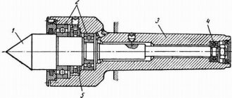
A scraper with a radius sharpening . Such a tool is shown in Figure 5 a, and its main difference from other types is that the cutting part 1 is sharpened along a certain radius, which greatly facilitates scraping, since such a tool requires much less effort (than when scraping with a flat scraper).
Radius and disc scrapers
We make the radius of curvature approximately 30 - 40 mm for preliminary scraping, and 40 - 55 mm for final scraping.
A disk scraper is shown in Figure 5b and, as can be seen there, the cutting part of such a tool is made in the form of a steel disk made of hardened (or high-speed) steel. This tool is used for scraping wide surfaces and can be made independently from a small disk cutter by grinding off its teeth and then finishing the edge of the disk on a sharpening machine.
The disk has an outer diameter of approximately 50-60 mm, with a thickness of 3-4 mm and is usually attached with a nut 2 to the end of the tool rod 3. And if the cutting edge of the tool becomes dull, you just need to turn the disk a little, loosening nut 2, then tighten it and you can continue working with the undull area. Of course, when the entire cutting edge of the disk becomes dull, it is removed and sharpened on a cylindrical grinding machine.
Sharpening and finishing of scrapers.
The sharpening of this tool is carried out on sharpening machines (more about the machines here) and anyone who is familiar with sharpening and finishing turning tools (more about sharpening the tools here) can sharpen almost any scraper without any problems. In this matter, it is important to choose the right sharpening angle and sharpen the cutting edges of the tool at the desired angle.
And the sharpening angles of the cutting faces (edges) should be selected depending on the material of the parts being processed, as well as on the nature of the work. The cutting edges of flat scrapers are their end ribs. Figure 6 shows the sharpening angles of a flat scraper depending on the material being processed, and also indicates the angles (installation angles) at which the tool should be held when working.
Angles of installation of the scraper and its finishing: a - finishing of the end of the scraper, b - finishing of the side surface of the scraper; Sharpening angles of scraper for scraping: c - cast iron and bronze, d - steel, d - soft alloys.
So for scraping parts made of cast iron and bronze, the sharpening angle is 90-100°, for scraping steel, as a rule, the sharpening angle is 75 - 90° (the softer the steel, the smaller the angle), but for scraping parts made of soft metals, the sharpening angle is only 35-40°.
In addition to Figure 6, recommended sharpening angles, depending on the material being processed, are shown in the table. In addition, the sharpening angles of triangular scrapers are indicated there, as well as the installation angles of the tool during operation and cutting angles.
The most common tool sharpening is at a sharpening angle of 90°, since scraping is mainly used to restore the guides of metal-cutting machines, in which the guides are made of cast iron. With a sharpening angle of 90° and setting the tool at an angle of 15-25º, the cutting angle will be approximately 105-125º.
At this cutting angle, the tool removes metal quite easily and does not cut into it too much, nor does it slip. Well, as I already said, the most common and rational form of blade sharpening is the radius shape.
TABLE of recommended cutting angles for flat and triangular scrapers.
The angle of installation of the tool can be much larger (75-80°) when working with the forward method, but more about this below, in the “scraping practice” section.
Practice sharpening and finishing scrapers.
As mentioned above, sharpening of the cutting surfaces of the tool is carried out on sharpening machines, with a grinding wheel (see the link above for information on sharpening machines and various grinding wheels). For flat scrapers, the side edges should be sharpened first, and only after that the end surface of the tool should be sharpened. Well, after this, finishing is carried out, which is done manually on a cast-iron plate coated with fine abrasive powder or paste.
During finishing operations, the tool is placed in a strictly vertical position (see Figure 6a above) and first the end cutting edge is adjusted (tucked) (moving the edge of the tool along the plate back and forth, with slight pressure), while it is important to hold the tool strictly vertically. Well, after that the side edges are finished (see Figure 6b) by moving the tool along the cast iron plate to the right and left (indicated by the arrow in the figure).
If you polish the tool in the sequence I described above, this will allow you to get the sharpest edges of the cutting edge, while there will be no blockages on the tool from finishing the end face. During intensive work, refueling (straightening, fine-tuning) of scrapers usually needs to be done again after a couple of hours of intensive work.
And after four or five refills, the tool must be sharpened and fine-tuned again. Although this is, of course, approximate data and everything depends on the quality and hardness of the material of the cutting blade of the tool, and on the hardness of the workpiece.
Scraping process, precision and quality control.
Scraping is the final finishing treatment of the surfaces of parts by scraping (removing) a very thin layer of material from the desired areas using a scraper, described in detail above. Scraping is used in cases where it is necessary to ensure very precise contact of the surfaces of rubbing parts and to obtain a tight fit of the surfaces of mating parts, and to give the parts precise shapes and sizes.
This operation is often used to restore the tight fit of the rubbing surfaces of metal-cutting machine parts (for example, bed guides and calipers) and restore the accuracy of worn machines.
Allowances for scraping should be small, as it was said above, during the scraping process the tool removes very thin chips, only 0.002 - 0.005 mm thick. And of course, the allowances depend on the length and width of the surface being machined (or on the diameter and length of the hole being machined).
Below are the values of allowances for scraping in millimeters, depending on the length and width of the planes and holes:
- The width of the processed surface is up to 100 mm, and the length is from 100 to 500 mm—the allowance is 0.10 mm.
- The width of the processed surface is up to 100 mm, and the length is from 500 to 1000 mm - the allowance is 0.15 mm.
- The width of the processed surface is up to 100 mm, and the length is from 1000 to 2000 mm - the allowance is 0.15 mm.
- The width of the processed surface is up to 100 mm, and the length is from 2000 to 4000 mm - the allowance is 0.15 mm.
- The width of the processed surface is up to 100 mm, and the length is from 4000 to 6000 mm—the allowance is 0.15 mm.
- The width of the processed surface is 100-500 mm, and the length is from 100 to 500 mm - the allowance is 0.15 mm.
- The width of the processed surface is 100-500 mm, and the length is from 500 to 1000 mm - the allowance is 0.20 mm.
- The width of the processed surface is 100-500 mm, and the length is from 1000 to 2000 mm - the allowance is 0.25 mm.
- The width of the processed surface is 100-500 mm, and the length is from 2000 to 4000 mm - the allowance is 0.30 mm.
- The width of the processed surface is 100-500 mm, and the length is from 4000 to 6000 mm - the allowance is 0.40 mm.
- The width of the processed surface is 500-1000 mm, and the length is from 100 to 500 mm - the allowance is 0.18 mm.
- The width of the processed surface is 500-1000 mm, and the length is from 500 to 1000 mm - the allowance is 0.25 mm.
- The width of the processed surface is 500-1000 mm, and the length is from 1000 to 2000 mm - the allowance is 0.30 mm.
- The width of the processed surface is 500-1000 mm, and the length is from 2000 to 4000 mm - the allowance is 0.45 mm.
- The width of the processed surface is 500-1000 mm, and the length is from 4000 to 6000 mm - the allowance is 0.50 mm.
The surfaces of parts intended for scraping are prepared in advance on planing, milling or grinding machines, and the surfaces of small parts are filed manually, first with a large (scraper) file and then with a small (personal) file.
Of course, this does not apply to the surfaces of machine tools (guide frames and supports) that wear out and need to be restored using scraping (on the topic of restoring machine bed guides and supports, I will write a separate article someday - the article has already been written and is located here and those interested can click on link and read). Although some machines (their guides) are first restored by grinding, but of course everything depends on the degree of wear of the surfaces and on the capabilities of the repair shop.
Before scraping the surface, you still need to process (remove) sharp edges along the entire perimeter of the workpiece surface. Next, you will need a surface plate, which is thoroughly wiped with a clean rag and then a uniform thin layer of paint is applied to it, which is a mixture of motor oil and soot powder or blue (Prussian blue), which should be crushed so much that you can’t even feel it between your fingers. small grains (you can use a coffee grinder as a grinder).
To obtain an even and uniform layer, apply the prepared paint using a canvas rag, and apply the paint from the inside of the rag. And protruding through the pores of the rag, the paint, when moving along the surface of the slab of the rag, covers the slab with a thin and uniform layer.
Now you should thoroughly clean the surface of the part with a clean rag and place the part on a paint-coated plate. Well, then all you have to do is apply light pressure on the part, make two or three circular movements on the plate, then carefully separate the part from the surface plate and examine the surface of the part. Painted spots on the surface of the part indicate protruding areas that need to be removed by scraping.
In the same way, the mating parts of the machines are checked, for example, the slides of the supports and the guides of the frames, only instead of a plate we paint a special ruler, for example ШД - 630 (GOST 8026) and apply it to the guides of the frame along which the machine support moves (or paint one of mating planes of the longitudinal and transverse slides of the caliper). As I already said, this topic is for a separate article and I will definitely write it (I have already written it and the link to the article is just above), since it is quite relevant.
The practice of scraping.
The scraping process itself consists of gradually removing metal from painted areas (painted areas mean bulges, and unpainted areas mean depressions). To begin with, we proceed to the so-called “breaking” of large spots, in which we remove (scrape off) the shavings from the convex (painted) places with strong movements of the scraper.
Next, we clean the surface of the part from chips and again check for paint as described above, and after that we repeat the scraping process again, scraping the metal from the convex places. And when the spots on the surface are evenly distributed, we finish the “breakdown” and begin to increase the number of spots, scraping off the newly appearing (after checking for paint) painted areas.
Scraping practice - a - installing a scraper, b - self-scraping, c - checking the accuracy of scraping.
Of course, each subsequent removal of metal (chips) will help reduce the height of the irregularities, which will be divided into several smaller convexities, and their total number will increase each time, while the direction of the working stroke of the tool should be changed each time, but more on that in a moment Later.
During the scraping process, we hold the scraper with our right hand by the handle (if you are right-handed), and set it at the desired angle in relation to the workpiece surface (I wrote above about angles, depending on the hardness of the material, and showed them in Figure 6). Well, with your left hand we press on the tool (see Figure 7a) approximately slightly below its middle.
It should be approximately taken into account that the pressure of the hand on the tool should be within 2-5 kg, no more. Well, during the reverse (idle) stroke back, we don’t put any pressure on the tool at all. Even beginners should take into account that scraping is performed in several transitions, and the tool should be moved in different directions so that the next stroke (stroke) overlaps the previous one.
More precisely, the next stroke should be at an angle of 45 - 90 degrees to the previous stroke. This is how the so-called “frost” of various shapes appears, that is, symmetrically located marks (stripes) or cells, or diamonds (see Figure 7). They also help retain the lubricant on the rubbing parts mating to each other, which is important (as important as the risks from the hone, which keep the engine oil on the surface of the engine cylinders). I hope this is clear to beginners, let's move on.
When semi-finishing and finishing scraping, it is best to use the method on yourself, in which the scraper, which has a length of approximately 45 - 55 cm (sometimes more - depends on the height of the worker), is grasped by the middle part with both hands, and the upper part with its handle rests against the worker’s shoulder. In this case, we try to position the tool at an angle of 75-80° relative to the surface being processed.
With this method, the working stroke of the tool is the movement of the blade towards itself and with this method it is much more convenient to work, the position of the tool is more stable, accordingly the quality of processing improves and, in addition, higher productivity is achieved (about 1.5 - 2 times) compared to using the usual scraping method.
Well, another important point - with this method, the long scraper springs better, which ensures smooth cutting of the blade and much greater processing accuracy.
Checking the scraping quality.
The quality is first checked by external inspection, and the scraped surface should not have deep scraper marks or scratches. Well, the accuracy of scraping is checked by the number of spots located on the area of a square, each side of which is 25 mm. As a square, special frames are used (see Figure 7c) with sides equal to 25 mm, which are easy to cut yourself.
Having attached the frame to the scraped surface, you should then count the number of spots inside it (inside a square with sides of 25 mm). Moreover, the number of spots on the entire scraped surface is determined as the arithmetic mean value calculated from several checks in different areas of the entire surface of the part.
In an area limited by a frame of 25x25 mm, for very rough scraping it is enough to achieve only four spots; for rough scraping, nine spots are enough; 16 spots are enough for precise scraping; well, for very precise scraping it is necessary to achieve 20 - 25 spots.
Precise scraping. For precision scraping, a paint test is not used, but usually a coarse or medium polishing paste from GOI (State Optical Institute) is used. After one or two passes with a scraper over the surface of the part, polishing paste is diluted with kerosene and applied to the surface plate. Then the part is placed on the surface of the slab with the surface to be rubbed and the scraped surface is rubbed in until the paste turns from green to black and this process is repeated three or four times.
After this, having thoroughly cleaned the surface of the part, inspect the surface on which shiny spots have appeared (which mean bulges) and darker spots remain, meaning depressions. Now you need to remove the shiny spots using a scraper, and again rub the surface with paste and repeat scraping until a surface of the required quality is obtained, which is determined again using a frame measuring 25x25 mm.
With the method described above (using paste), an important circumstance should be taken into account: the polishing paste can work not only on the surface of the part, but also on the surface of the surface plate. Therefore, it is imperative, before and after work, to carefully monitor the condition of the surface of the surface plate, for example, using a measuring ruler (in the light - the magnitude of the deviation from straightness is judged by the size of the light slit).
Despite the above-described troubles with checking the condition of the slab, the use of GOI paste allows you to increase the productivity of precision scraping by one and a half to two times.
Scraping curved surfaces (bearing shells).
Scraping curved surfaces, such as bearing shells, has some special features. Firstly, triangular straight or curved scrapers are used here (they are described above), and secondly, there are differences in operation.
scraping the liners: 1 - scraping the liner with a semicircular scraper, 2 - transparent celluloid template mesh for quality control, 3 - scraping with a shaped triangular scraper, 4 - scraping with a ring scraper.
First, apply a thin and even layer of paint to the area of the shaft that will come into contact with the liner. Then the painted shaft is placed on the lower liner(s) and then evenly (crosswise) and the bearing cap is tightened with slight force. We tighten the cover nuts to such an extent that the shaft can be turned with some effort to the right and left, a couple of turns.
At the initial stage, you can not clamp the bearing caps, but simply place the shaft in the lower bearings and, pressing it a little, turn it to the right and left 2-3 turns.
After this, unscrew the nuts and remove the bearing cap and shaft, and then scrape down the painted areas of the liner (meaning bulges) by moving the tool along the shape of the liner’s circumference. We tilt the scraper towards the surface of the liner so that the middle part of the cutting edge of the tool removes the metal.
The tool is given a slight rotational movement and at the same time pressed against the surface of the workpiece. Next, we repeat the paint and scraping test until at least 3/4 of the liner's surface area is evenly covered with paint stains.
But more precisely, the quality of scraping can be checked by cutting out a template from cardboard, which has the same 25x25 mm window and applying it (by bending the template) to the surface of the liner. If the insert is large, then you can make a template from transparent plastic (celluloid - shown in the figure just above), on which to draw a grid, with cells again measuring 25x25 mm.
Mechanization of scraping. Scraping is a rather labor-intensive plumbing and fitting (finishing) operation. For example, to scrape a cast iron surface with an area of 2 square meters, it is necessary to spend more than 100 hours of labor of a qualified worker. Therefore, the mechanization of such work in production is of great importance.
For mechanized scraping, various special devices are used to speed up and facilitate the scraping process. These include pneumatic scrapers, operating on the principle of a jackhammer using compressed air, and electro-mechanical tools, powered by electricity. All of them have practically the same operating principle - the conversion of electricity (or air pressure energy) into the reciprocating movement of the scraper cutting plate.
But still, mechanical scraping is more suitable for large areas and volumes of work in production. Therefore, I will not describe it in detail. Well, the manual method is considered more accurate and accurate, and it is best suited for garage craftsmen and their workshops.
Defects during scraping and measures to prevent it.
- Type of defect: complete covering of the scraped metal surface with paint. Reason for defect: applying too thick a layer of paint to the surface plate (or ruler). Precautionary measure: carefully apply paint (Prussian blue) in a thin layer.
- Type of defect: coloring of the edge or middle of the surface being scraped. Reason for defect: improper pre-treatment of the metal surface. Precautionary measure: check the correctness of the surface pre-treatment.
- Type of defect: the presence of shiny stripes on the metal surface being scraped. Reason for defect: scraping in one direction only. Preventative measure: we scrape in different directions so that the strokes are located at angles of 45 - 60º.
- Type of defect: uneven distribution of stains on the surface to be scraped. Reason for defect: too much pressure on the scraper, or scraping with too long strokes. Precautionary measure: when scraping, be careful and do not put strong pressure on the tool, and also do not make too long working strokes of the tool. When rough scraping, the tool stroke should be no more than 10 - 15 mm, and when finishing scraping, the stroke should be no more than 5 - 10 mm.
- Type of defect: formation of scratches on the metal surface being scraped. The reason for the defect: poor quality filling (finishing) of the tool, or the presence of burrs on its edges, or solid impurities getting into the paint. Preventative measure: check the quality of the threading and the condition of the cutting edge of the scraper blade. Next, we check its operation on an unnecessary part. We check the quality and composition of the paint; by the way, if it is applied through a swab made of finely porous fabric, then the likelihood of solid particles getting in is reduced to zero.
- Type of defect: deep depressions on the surface being scraped. Reason for defect: too much pressure on the scraper. Preventative measure: we prepare the part for scraping in advance using preliminary filing and rough scraping with small gaps. When scraping, do not put too much pressure on the tool and remove chips of small thickness.
- Type of defect: the presence of burrs and roughness on the surface being scraped. The reason for the defect: improper sharpening and finishing of the scraper, as well as its incorrect movement during scraping. Preventative measure: we sharpen and fine-tune the tool correctly to avoid working with a dull blade, and also read above about the correct use and correct movements of the tool.
- Type of defect: inaccuracy of the scraped surface. The reason for the defect: the use of an inaccurate verification tool, or improper use of it, or incorrect movement of the scraped part along the verification tool (or vice versa, the tool over the part) when checking for paint. Preventative measure: we promptly check the accuracy (or straightness) of the calibration tool, and also keep the working surfaces of the calibration tool and the surfaces of parts clean. Well, we don’t press too hard on the testing tool when checking for paint (we use the tool correctly).
That seems to be all, if I remember anything else, I’ll definitely add it. I hope that the tool described here - the scraper, and the scraping process itself, I have described in sufficient detail and this material will be useful to novice craftsmen, good luck to everyone.
If this article is useful to you, please share it on social media. networks by clicking the buttons below. Thank you.
RќСЂР°РІРёС‚СЃСЏ
CONTROL OF APPEARANCE AND MARKING OF INSTRUMENTS
2.1. Defects in the appearance of tools are divided into critical and minor according to GOST 15467-79.
The classification of defects is indicated in Table 2.
Critical defects are not allowed.
2.2. The appearance of the tools must be checked according to a one-step control plan in accordance with Table 6.
2.3. The batch is considered to have passed acceptance control if the number of defects in the sample is less than or equal to the acceptance number specified in Table 6, and the batch is considered to have failed acceptance control if the number in the sample is equal to or more than the acceptance number specified in Table 6.
2.4. Control of the appearance and marking of instruments for export must be continuous.
Section 2. (Changed edition, Amendment No. 2, 3).
Class of defects in the appearance of tools according to GOST 15467-79
Prefabricated tool: the absence of elements or parts of a prefabricated tool that affect the performance of its main functions.
Defects in tools that impair performance and durability, affecting safety at work:
hot-stamped and cast tools have cracks, delaminations, caps, hairlines, sunsets, chains, shells, sand, fistulas, bubbles, burns, sprues, profits, traces of corrosion, burrs (keys, wire cutters, pliers, pliers, vices, hammers, chisels , bits, center punches, screwdrivers);
welded tools have fistulas in the welding areas and visible rupture of the solder layer over 50% of the total length along the soldering contour (pipe and socket wrenches, stamps, compasses);
synthetic parts of instruments have cracks, delaminations, cavities, bubbles, gouges, and chips;
wooden parts of tools have cracks, gouges, bumps, chips, chips, rot, wormholes, and sprouts.
A tool designed to work under electrical voltage: lacks electrical insulation.
Tool handles: presence of sharp edges, burrs, flash and burr
Stamps, beards, punches, crimps, chisels, crosscuts: the presence of crumbled places and blockages on the cutting, working and impact parts.
Nippers, scissors, combination pliers:
the presence of blockages, nicks, chips and burns on the cutting and working edges.
The presence of blockages, dents and burrs on the teeth of the pliers tool
Hammer heads: presence of crumbled areas on the striker and toe.
Hammer handle (from the head side): the presence of more than one healthy fused knot with a diameter of more than 5 mm at a distance of 2/3 of the length.
Presence of cracks, rot, growth, wormholes, sagging, cavities, bubbles, dents and flash
Vices, clamps, wrenches, pipe wrenches: the presence of broken threads on the threads
Fuzzy markings
The presence on non-working surfaces that are not subject to machining, nicks, rough spots, dents from scale, blockages, traces of corrosion with an area of no more than 10%, traces of stamping along the parting line
Tool handles: the presence of dull remains of flash and burr no higher than 0.3 mm
Hammer handle (from the head side): the presence of one healthy fused knot with a diameter of no more than 5 mm at a distance of 2/3 of the length