- Straight through turning tools and their purpose
Lathe cutter design
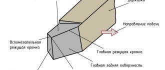
Different types of cutters for a lathe differ in shape, the presence of additional blades, and teeth. However, the overall design remains unchanged. The equipment consists of two main elements:
- Rod is another name for “holder”. A piece of equipment that is attached to equipment.
- Working part. The sharpened element of the cutter that comes into contact with the workpiece. Depending on the design features, the plate in contact with the workpiece may consist of many cutting edges and working planes.
When working with equipment for turning equipment, we must not forget about the importance of sharpening angles of the working part. There are three angles in total, changing which will affect the result.
What are the current standards and the explanation of their markings?
The main standard by which turning tools are manufactured is GOST:
- Cutting and groove - GOST 18874-73.
- Boring - GOST 18872-73.
- Walkthroughs - GOST 18871-73.
- Shaped - GOST 18875-73.
- Threaded - GOST 188885-73.
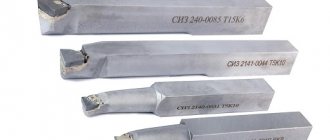
Marking according to the material of the working part:
- Tungsten - VK8, VK2.
- Titanium tungsten - T5K10, T15K6, T30K4.
- Titanium-tantalum-tungsten - TT7K12, TT8K6.
- High carbon steel - U10A, U12A.
- High-speed steel of normal efficiency - P9, P12, P18.
- High-performance high-speed steel - R18F2, R18F4, R6M3.
This is interesting: How to restore chrome: cleaning and restoration of chrome coating
Cutter geometry
There are different types of cutters, which differ in size, shape of the holder and the number of planes on the working head. For example, the rod for securing the equipment can be round, rectangular, or square. The working element of the device is a set of surfaces
— Incisors are divided into right-handed and left-handed. The difference lies in how the cutting edge is positioned relative to the holding part.
Tips for choosing quality cutters when purchasing
To choose the right cutters for a particular case, you need to rely on the following important parameters:
- Which metal is processed most often? What operations are performed on the equipment?
- It is important to prioritize in advance between wear resistance, processing efficiency and product quality.
If a turner is just starting to work, then he only needs to purchase three types of tools:
- Boring SDQCR.
- Neutral external type
- Pass-throughs for processing ends. SDACR.
Sets with lathe cutters are relevant if long-term operation is planned. The advantage is kits with replaceable plates. There is no need to purchase new holders; it is enough to change the consumable components.
As for manufacturers, here are a few names worthy of attention:
- Caliber.
- Sieve.
- Proma from the Czech Republic.
- Hoffman Garant from Germany.
The first two manufacturers are Russian. It would be important to purchase a special sharpening machine. Then, if the incisors wear out, returning them to working capacity on your own will not be a hassle. No need to waste time waiting for the masters.
Two wheels with abrasive properties and support for the cooling system are becoming important components for modern sharpening and grinding units. One disk is made of silicon carbide, the other is based on electrocorundum. The front part of the cutter is processed first, followed by the rear surfaces and the addition. The goal is to obtain a smooth edge that can cut through materials.
This is interesting: How to weld stainless steel with ferrous metal: technology features
Classification of cutters for turning
There are state standards that describe the classification of turning tools. One of the classifications is the division according to the type of processing of metal surfaces:
There is a division according to the type of material from which the working part of the equipment is made. A separate classification concerns the integrity of the equipment design:
- One-piece fixtures. They are accessories for lathes made from alloy steel. Models made of tool steel are rare.
- Devices with additional plates. They are made at the factory from different types of hard metals and alloys.
- Models with removable plates. They are fixed to the holder using screws. Rarely used during serial processing of metal parts.
The main classification is the division of devices into separate types according to shape and design. We need to talk about them separately.
Cutting speed, feed rate and depth of cut
Determination of cutting speed, feed rate and chip thickness
The cutting speed of any operation consisting of removing chips or cutting metal is expressed in meters per minute or millimeters per second. For lathes, the cutting speed is equal to the length traversed by the cylindrical (with cylindrical turning) or end (with frontal turning) surface of the product per unit time along the cutter blade. If one could accurately measure the length of chips removed by a cutter in a minute (or second), it would represent the cutting speed.
The feed rate or simply feed (feed) during turning is the amount of movement of the cutter along the workpiece per one revolution of the latter. If, for example, when turning a shaft, the feed is 0.5 mm, this means that when the product makes 100 revolutions, the caliper will move by 0.5 x 100 = 50 mm. The expressions often used are: “large” or “large” feed, “small” or “thin” feed. These expressions make sense only when talking about machines of approximately the same power. It is clear that the same feed can be “small” for a large machine and “large” for a low-power machine.
The cutting depth is the thickness of the metal layer removed by the cutter; This is sometimes also the name for the thickness of the chips removed, although these values are not quite the same due to the deformation of the metal during cutting. Let us assume, for example, that a steel blank with a diameter of 50 mm needs to be turned on a lathe to a diameter of 47 mm in one pass. It is clear that the cutting depth should be (50 - 47) /2 = 1.5 mm.
Time Element
One of the main factors that determines the productivity of a machine or workshop is time. The time at which the metal is removed from the product depends on the time it takes to completely process it. The amount of chips removed depends, in turn, on three elements - depth of cut, feed rate and cutting speed. Let's take turning as an example.
- Let's assume that it is necessary to reduce the diameter of the product from 50 mm to 47 mm, i.e. The cutting depth should be 1.5 mm. If the cutter can take such chips in one pass, then there is no point in making two passes, removing 0.75 mm chips, since turning would require twice as much time. Therefore, the first productivity factor is the depth of cut.
- If, with one revolution of the product, the cutter is fed by 0.4 mm, while it could be given a feed of 0.8 mm, then to pass a certain length, twice the number of revolutions of the product will be required, in other words, all other things being equal, twice as long. Thus, the feed rate is the second factor affecting the processing speed.
- Let the diameter of the product be 50 mm and its rotation speed 65 per minute. The cutting speed is obviously: π ✖ 0.050 ✖ 65 = 10 meters per minute. If the cutter can operate (without abnormally frequent regrinding) at a cutting speed of 20 meters/min, then it is uneconomical to give the machine spindle only 65 rpm. Therefore, the third productivity factor is cutting speed.
The task of productive and economical workshop operation therefore comes down to the skillful selection of cutting speed, feed rate and depth of cut for each job and the selection of the appropriate machine. Successful selection of these elements requires a lot of experience. It’s easier to find them by counting using known formulas.
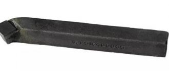
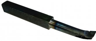
Boring cutters for through holes
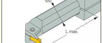
This is equipment for industrial equipment. It is used for boring holes created by drilling. The depth of machining of the holes depends on the length of the part fixed in the caliper. The element with the cutting edge has a bent head. The thickness of the material removed by the cutting edge is almost equal to the bend. The maximum length of the holding part is 300 mm.
How to install on the machine
To obtain the proper quality and precision of processing, correct installation of the cutter is necessary. Also, installation errors contribute to rapid wear of the cutting edge.
The tool is installed in the tool holder strictly in the center. To adjust it in height, the turner must have metal plates with a thickness of 1 to 4-5 mm in his arsenal. Setting below center causes the part to be pushed out, which is dangerous for both the tool and the worker. If the cutting edge is too high, it overheats and wears out quickly.
When installing a cutting tool, you need to follow simple rules:
- Wipe the supporting surface of the tool holder.
- Secure the tool with at least two bolts.
- The overhang of the head should not exceed 1.5 times the height of the holder.
- When roughing, it is allowed to overestimate the cutting edge by 0.3-1 mm.
After installing the tool, you need to remove test chips. If the surface is flat and smooth, the chips do not wrap around the cutter, you can start working.
Important!
Do not use more than three gaskets. Also, they should not protrude beyond the tool holder.
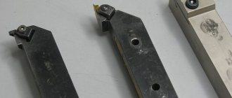
Prefabricated cutters
Perform various technological operations. The design allows you to attach different carbide inserts to the holder. The presence of several working elements allows you to increase the versatility of the device. The cutters, which are assembled from different plates, are fixed in the spindles of equipment controlled by a CNC system. Using prefabricated devices, holes are machined, contours are made, and grooves are selected.