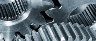
In this tutorial we will learn how to create gears. A gear wheel (gear) is the main part of a gear transmission in the form of a disk with teeth and is designed to transmit rotation between shafts. There are 2 main types of gears - cylindrical (straight, helical, chevron, circular teeth, etc.) and conical (with circular (screw) and straight teeth). Construct a gear profile using conventional Compass-3D tools, such as extrusion And extrusion cutting is problematic, since the gear tooth profile is built along a complex curve - an involute.
Video course on this topic
Video course “Basics of design in KOMPAS-3D v19”
0 out of 5
The video course is aimed at mastering the basics of design in CAD KOMPAS-3D. Training is carried out using the example of creating models of components and assembling an industrial device from them, analyzing the features of modeling and visualizing the results in...4500 rub.
Add to cart Quick view
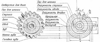
Involute meshing of gears
For these purposes, Compass-3D has a library Shafts and mechanical transmissions , which is located in the application - mechanics .
As an example, let's take a helical gear with the number of teeth z=55, module m=10 and inclination angle =15°13′21″ .
When you launch the library, a panel of basic settings for the future gear appears on the left, such as the type of gearing, chamfer sizes, model display parameters and a table with teeth parameters. The choice between the construction of the driving and driven wheels is carried out with the button Change element . To edit the parameters of the teeth, click the Calculation in the “KOMPAS-GEARS” module and select the geometric calculation in the menu that appears. In the table that opens, set the required values for the drive wheel and, if required, for the driven wheel on the page 1 and go to the page 2 .
Page 1 of geometric calculation
On this tab we will also adjust the values, if necessary. To start the calculation, click the Calculation button, after which the program will perform the calculations and indicate possible errors or their absence at the bottom of the window.
Page 2 geometric calculation
On this page you can also write the received data to a separate file or view the data in a separate window. mesh rendering button is only available in 2D creation mode. To complete the calculations and proceed to building the model, you need to click finish calculations. Now, after closing the window for constructing teeth, you can add adjustments to the main gear parameters and click OK
The resulting gear model
The result is a gear model with a given module, diameter, tooth angle , etc. Now you can move on to constructing the remaining elements of the wheel: holes, splines, grooves and other elements provided for by the design.
In addition to teeth, gears use holes or shafts (gear shafts) with keyed or splined connections, created in accordance with current GOSTs, to transmit rotation. These elements are also created in the Compass-Gears library, but their creation will be described in more detail in the lesson “Mechanical gears in Compass-3D”
Creating a bevel gear model is done in the same way, the only difference is in choosing a library; instead of a cylindrical one you need to select a bevel one.
Library path for bevel gears
Then also launch the “ KOMPAS-GEARS module and enter the data of your bevel gear .
Window for entering parameters for constructing a bevel gear
Further actions are similar to those for constructing a cylindrical gear.
Manufacturing materials
The gear worm gear is characterized by increased jamming and wear of the working surfaces. This occurs due to unfavorable operating conditions of the node. Due to the non-formation of an oil wedge at the point of the engagement pole. To increase wear resistance and prevent jamming, structures are made of metals with high anti-friction properties.
The following alloys are used in the production of worm wheels:
- high- and low-tin bronze;
- soft gray cast irons;
- brass;
- tinless bronze.
To save metal, the worm wheel is designed as a composite wheel. The crown is made of brass or bronze. The central part of the gear is made of steel, cast iron. Designs can be of the following types:
- bandaged;
- bolted;
- bimetallic.
In the first case, the bronze crown is installed with tension on the center of the wheel. Additionally secured with screws, from 3 to 8 pieces. In a bolted design, the crown has a flange with holes. 4 to 8 tight-fitting bolts are installed in them without clearance for fastening to the center of the wheel. In mass production, the bimetallic method of producing gears is more often used. The center of the wheel is first set in the mold, and then molten metal is poured. The crown material for the worm wheel is selected depending on the operating conditions and the required wear resistance of the product. Bronze is more expensive than steel, so components up to 16 centimeters in size are made entirely from it.
Creating a Gear Drawing
In addition to creating models, this library allows you to create flat drawings, while they are created annotative and if in the future you can create a three-dimensional model from them.
To create such a drawing, create file and open the library Applications – Mechanics – Shafts and mechanical transmissions 2D – building a model. Let's select Elements of mechanical transmissions – Gears and racks – Spur gear with external teeth, or another one from the list. A window with spur gear data opens. As you can see, most of the fields are inactive and without data. In the Gear Type , you can change the gearing type. To enter data for constructing the gear, click the Start calculation .
Data window for gear construction
As before, select Geometric calculation and the appropriate calculation option in the appearing windows. Next, in the same way as in three-dimensional modeling, we will fill out the data table for the geometric calculation of our future gear. To continue the calculation, you must fill in both columns of the Drive Wheel and Driven Wheel, otherwise page 2 will be unavailable. If you need to create only one wheel for your work, then you can enter arbitrary the number of teeth and the width of the ring gear
Window of gear geometric parameters
Next, we repeat all the steps as in the previous section on building a three-dimensional model of a gear. After entering all the data, a window will appear with the parameters already entered. At the bottom of the window you can set chamfer, rounding and backing .
Data window for constructing a gear with entered gear parameters
To finish, click OK at the top of the window.
The resulting gear drawing
To edit the drawing, in the construction tree, select the line labeled Macro:36 (the numbers may be different) and click Edit macroelement. Then, in the Shafts and Mechanical Gears 2D , select the required gear from the list and double-click on it with the left mouse button .
Editing a macronutrient
Advantages and disadvantages
In comparison with analogues that have other design designs in terms of action, worm gears are more popular. Transmission units produce higher torque. When moving, the worm thread moves along the axis, which pushes and directs the teeth of the wheel in the desired direction.
The main advantages of gear worm wheels are as follows:
- compact dimensions, convenient assembly;
- high level of gear ratios, 8-80, sometimes up to 100;
- silent operation of the unit;
- smooth ride;
- self-braking system.
A high level of gear ratios allows you to increase the possibility of reducing rotation speed and increasing torque. The wheels provide a high level of grip, which eliminates noise.
A pair of worm and worm wheel has a smooth motion and is capable of rotating in both directions. Allows for the smoothest braking during operation. When the transmission stops moving, the self-braking system slows down the speed of the drive shaft to a full stop.
The disadvantages of worm gears in gearboxes include the following disadvantages:
- high friction causing low efficiency due to increased transmission ratio parameters, energy losses;
- when there is an excess of kinetic energy and the impossibility of its complete transfer, overheating of the unit occurs;
- noticeable play of the output shafts, which increases with intensive use;
- relatively short service life, on average up to 10 thousand hours.
GOST 2.402-68 ESKD. Conventional images of gears, racks, worms and chain sprockets
STATE STANDARD OF THE USSR UNION
UNIFIED SYSTEM OF DESIGN DOCUMENTATION
RULES FOR EXECUTION OF DRAWINGS OF VARIOUS PRODUCTS
CONVENTIONAL IMAGES OF GEARS, RACKS, WORMS AND SPROCKES OF CHAIN TRANSMISSIONS
GOST 2.402-68 (ST SEV 286-76)
MOSCOW - 1998
STATE STANDARD OF THE USSR UNION
| Unified system of design documentation CONVENTIONAL IMAGES OF GEARS, PEEK, WORMS AND CHAIN TRANSMISSIONS Unified system for design documentation. Conventional representation of gears, racks, worms and chain wheels | GOST 2.402-68 (CT SEV 286-76) Instead of GOST 3460-59 |
Approved by the Committee of Standards, Measures and Measuring Instruments under the Council of Ministers of the USSR in December 1967. The introduction date is set
from 01.01.71
1. This standard establishes conventional images used when making drawings of gears, racks, worms and chain sprockets, as well as when making assembly drawings containing these parts.
The standard corresponds to CT SEV 286-76.
2. Conventional images of gears, racks, worms, and sprockets of chain drives must be made according to the rules set out in paragraphs. 3 - 12, and correspond to the drawings indicated in table. 1 and 2.
3. The teeth of gear wheels, chain sprockets and turns of worms are drawn in axial sections and sections, the teeth of racks - in transverse ones.
In other cases, the teeth and turns are not drawn and the depicted parts are limited to the surfaces of the protrusions (Table 1, Figures 1 - 9).
If it is necessary to show the profile of a tooth or coil, draw the tooth or coil on the extension element; it is allowed to show them in a limited area of the image of the part (Table 1, Figure 1 b
, 6).
4. The circles and generatrices of the surfaces of the protrusions of teeth and turns (cylinders, cones, etc.) are shown with solid main lines, including in the engagement zone (Table 1, Figures 1 - 9; Table 2, Figure 1 - 4, 9, 11, 12).
5. The drawings of gears, racks, worms, and sprockets of chain drives show pitch circles, pitch lines forming pitch surfaces (cylinders, cones, etc.) and circles of large bases of pitch cones (Table 1, drawings 1 - 6 , 8, 9).
6. Assembly drawings of gears and worm gears show initial circles, initial lines forming the initial surfaces and circles of the large bases of the initial cones (Table 2, drawings 1 - 11).
7. In the drawings of globoid worms and the wheels mating to them, as well as in the assembly drawings of globoid worm gears, the design circles and generatrices of the design surfaces are shown (Table 1, Drawing 7; Table 2, Drawing 12).
8. The dividing, initial, and calculation circles and lines forming the dividing, initial, and calculation surfaces, the circles of the large bases of the dividing and initial cones are shown with dash-dot thin lines.
9. The circles and generatrices of the surfaces of the tooth cavities and turns in sections and sections are shown along the entire length by solid main lines.
On the views of cylindrical gears, worms, racks and sprockets of chain drives, it is allowed to show the circles and generatrices of the surfaces of the tooth cavities or turns, and they are drawn with solid thin lines (Table 1, Figure 1 b
, 8;
table 2, damn. 1 a
).
10. If the cutting plane passes through the axis of a gear wheel or sprocket, then in sections and sections of gear wheels and sprockets, as well as in transverse sections and sections of racks and worms, the teeth and turns are conditionally aligned with the plane of the drawing and are shown uncut, regardless of the angle of inclination of the tooth and helix angle (Table 1, Fig. 1 - 9).
11. If the cutting plane runs perpendicular to the axis of the gear or sprocket, along the worm or along the rack, then the gears, sprockets, worms and racks are usually shown uncut.
If it is necessary to show them dissected, a local cut is used and hatching is carried out to the line of the surface of the depressions (Table 2, Fig. 11 b
).
12. If the secant plane passes through the axes of both gear wheels that are in mesh, then in the section in the mesh zone the tooth of one of the wheels (preferably the drive) is shown located in front of the tooth of the mating wheel (Table 2, Fig. 1a
, 2 , 4
A
, 5 — 7 ).
If the secant plane passes through the axis of the worm wheel or worm, then the worm turn is shown located in front of the wheel tooth (Table 2, Fig. 11, 12).
If the secant plane passes through the axis of the rack and pinion gear, then the gear tooth is shown in front of the rack tooth (Table 2, Figure 3).
In the listed cases, invisible contours may not be drawn if this does not make the drawing difficult to read.
13. If it is necessary to show the direction of the teeth of a gear wheel, rack or worm turns, then three solid thin lines with a corresponding slope are applied to the image of the surface of the teeth or turns (usually near the axis).
In the image of a gear or rack gear, the direction of the teeth is indicated on one of the gearing elements (Table 2, Figure 1 b
,
c
,
d
, 4
b
; 9).
14. When depicting engagement by bevel gears with the intersection of the axes at an angle other than a straight line, the bevel wheel, the axis of which is inclined to the projection plane parallel to the axis of the paired wheel, is depicted by the circle of the larger base of the initial cone, aligned with the plane of the drawing; the same wheel, projected onto a plane perpendicular to the axis of the paired wheel, is represented by a triangle, the apex and base of which are obtained by projecting the apex and diameter of the large base of the initial cone (Table 2, Fig. 5, 6).
15. When depicting a helical engagement with the intersection of the axes at an angle other than a straight line, the wheel, the axis of which is inclined to the projection plane, is depicted as an initial circle aligned with the drawing plane (Table 2, Drawing 10).
16. When depicting chain drives, the chain is shown with a dash-dot thin line connecting the pitch circles of the sprockets (Table 2, Figure 13).
Table 1
| Name | Conditional image |
| 1. Spur gear | Crap. 1 |
| 2. Spur gear with internal teeth | Crap. 2 |
| 3. Bevel gear wheel | Crap. 3 |
| 4. Flat gear wheel | Crap. 4 |
| 5. Toothed worm wheel | Crap. 5 |
| 6. Cylindrical worm | Crap. 6 |
| 7. Globoid worm | Crap. 7 |
| 8. Toothed rack | Crap. 8 |
| 9. Chain sprocket | Crap. 9 |
table 2
| Name | Conditional image |
| 1. External engagement with cylindrical gears | Crap. 1 |
| 2. Internal engagement with cylindrical gears | Crap. 2 |
| 3. Rack gear | Crap. 3 |
| 4. External engagement with bevel gears with axes crossing at right angles | Crap. 4 |
| 5. External engagement with bevel gears with the intersection of axes at an angle other than straight | Crap. 5 |
| 6. Flat-conical gearing | Crap. 6 |
| 7. Palloid engagement | Crap. 7 |
| 8.Hypoid gearing | Crap. 8 |
| 9. Helical gearing with cylindrical gears with axes crossing at right angles | Crap. 9 |
| 10. Helical gearing with cylindrical gears with the intersection of axes at an angle other than straight | Crap. 10 |
| 11. Engagement with a cylindrical worm | Crap. eleven |
| 12. Engagement with a globoid worm | Crap. 12 |
| 13. Chain drive | Crap. 13 |