Requirements for installation, repair and operation
All gearboxes are supplied with a passport for compliance with technical manufacturing conditions and a passport for lubrication. The gearbox passport specifies the characteristics of the gearbox and the conditions of application. Operating personnel enter information about operating conditions, design changes, major repairs and safety devices, and inspection results into the gearbox passport. The lubricant certificate supplied with the gearbox indicates the recommended type of lubricant, quantity and frequency of replacement. The certificates are sent to the customer along with the gearbox and are used during the entire period of operation. Filling out and maintaining the passport is a mandatory condition to ensure normal operation of the gearbox.
8.6: Step gearboxes
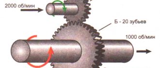
In some situations, a project may require the use of a mechanical advantage that cannot be achieved with a simple gear ratio, or is impractical. For example, if a VEX robot project requires a gear ratio of 12:500, this may be a problem since a 500-tooth gear does not exist. In this situation, the designer can use several gear reducers in one mechanism. This is called a step change in gear ratio (gear reduction).
In a stepped transmission system there are several pairs of gears. Each pair has its own gear ratio, and the pairs are connected to each other using an axis. The result is a stepped transmission system that, as before, has a drive and driven gear, and also has a gear ratio (now called a "compound ratio"). The complex gear ratio is calculated by multiplying the gear ratios of all gear pairs taken.
For the example presented above, the total gear ratio is calculated as follows:
Complex Gear Ratio = Number 1 x Number 2 = (60 / 12) x (60 / 12) = (5) x (5) = 25
This means that the output shaft rotates 25 times slower than the input shaft at 25 times the torque. Complex gear ratios add up easily!
The example above shows a gearbox consisting of twelve 12:60 gears in a stepped gearbox. This achieves a complex gear ratio of 224,140,625, which is almost a quarter of a billion to one. This means that the number of revolutions at the input equal to 244,140,625 will result in only 1 revolution at the output! Interesting fact: If the input rotates once per second, it will take approximately 7 years and 9 months to achieve one single revolution at the output.
Source
Mounting and installation of the gearbox
For normal operation of the gearbox, the following conditions must be observed during installation and installation:
- the foundation must be rigid and not allow individual parts to settle during operation (this distorts the shaft axes and creates additional forces on the bearings and shafts);
- When installing the gearbox, it is necessary to adjust the alignment of the axes of the shafts of the engine, gearbox and working machine.
When installing pulleys, sprockets, couplings, and gears on gearbox shafts, the mounted part should be preheated before seating to a temperature of 100-150 °C. Do not hit the mounted part directly with a hammer or sledgehammer as this may damage the gearing or bearings.
Application of the mechanism
The purpose of the gearbox is unlimited; most complex machines and units have it in the structure of the mechanism. In heavy industry, worm and cylindrical mechanisms are most often used to transmit force to the tool.
It is also the main component of the mechanism of any car, where several similar elements are used. It is found in the gearbox, driveshaft, gasoline pump, brake system and other components.
Some car owners think that the gearbox and differential have an identical design and perform similar functions. But unlike a gearbox, which changes torque, a differential distributes torque between the axles in a certain proportion, without increasing or decreasing it.
Pressure reducers can be found in gas production. Their use allows you to control pressure and change its direction, be it gas or water pressure. In the oil refining field, a similar mechanism is used in generator sets, various mixers, heating and ventilation systems. Cement plants use planetary models, which are components of conveyor belts that transfer huge amounts of materials. The purpose of wheel gearboxes is to operate belt conveyors.
Almost every production uses devices such as winches and lifts, each of which has a gearbox in its design. Similar mechanisms are found in earthmoving equipment, which is used in construction and industrial quarries.
You can find such models in various household appliances. But most often geared motors are found (in food processors, washing machines, rotary hammers and drills). Rotary hammers use a combination of planetary and geared motors, which allows for optimal performance of translationally rotating elements.
It should be noted that almost every modern complex mechanism cannot do without the use of a gearbox. This element can significantly increase engine performance, transfer force between structural elements and minimize wear of mechanisms. Choosing the appropriate model, timely maintenance and compliance with the standard load will allow you to fully use the gearbox throughout the warranty period, regardless of the scope of its use.
If you find an error, please select a piece of text and press Ctrl+Enter.
To change the torque characteristics, a special mechanism is used, which is called a “gearbox”. This word is derived from the Latin reductor - taking back or returning, which very accurately reflects the principle of operation of this mechanism. At the moment, there are several types of gearboxes that are used in various units to transform and transmit torque from the device’s engine to power consumers.
Read also: How to find wiring in a wall device
Starting the gearbox
Before putting the gearbox into operation, it is necessary, if possible, to turn the gear by hand before turning on the engine. If the gearbox overheats, check the oil level. The oil level must be within the limits specified in the technical documentation. If the oil level is within the acceptable range, it is necessary to check the correct installation of the gearbox.
Overheating of gearbox bearings occurs for the following reasons:
- additional load from subsidence of the foundation or misalignment of couplings;
- when the lubrication channels are clogged;
- excessively high oil viscosity;
- with large or small clearances in bearings.
The outside of the gearbox housing and cover must be systematically cleaned of dust, dirt, and oil. Heat dissipation from the enclosure depends on heat transfer through the outer surface.
Design and principle of operation
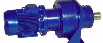
The design of the gearmotor consists of a mechanical gearbox and an electric motor connected into a single unit. Due to this, the process plant requires one installation location instead of two. There is also no need to ensure the alignment of the motor and gearbox shafts, or to select and install a coupling that transmits rotation. The general design of the gearmotor has some differences from the separate options. The transmission housing is manufactured with the necessary safety margin to ensure reliable operation of the device with a fixed heavy motor. To mount the engine on the housing, special seats are made. The design of the gearbox drive gear includes cylindrical holes used to install the drive motor shaft. The housing is additionally provided with fastening elements for mounting the geared motor into the process unit. Any type of electric motor can be used as an electric drive for the gearmotor. The most common models are those using standard asynchronous electric motors. To implement a monoblock design, flange-type models are chosen.
The operating principle of a gear motor does not differ from the operation of a classic electric gear drive. The rotational torque of the engine is transmitted to the drive gear, which is actually mounted on the motor shaft. Thanks to gearing, the torque is converted by one or more driven elements, which in turn influence the shaft of the technological mechanism.
The output rotation speed depends on the motor parameters and the gear ratio. To obtain an increased conversion factor, multi-stage models are used. If speed correction is necessary, geared motors are easily integrated into systems with speed control via controlled converters.
Source
Lubrication
Normal operation of the gearbox is ensured only if the type of oil specified in the passport is used. When removing foreign particles from the oil from the initial wear of the gears, after the first two weeks of operation, stop the gearbox, drain the oil and rinse the gears with warm oil. The oil should be filtered and poured into the gearbox. The oil change is carried out once after 3-6 months of operation of the gearbox, during scheduled preventive maintenance of the unit.
The pour point of the lubricant used must be below the minimum ambient temperature. The oil bath temperature of spur and bevel-helical gearboxes during continuous operation should not exceed 60 °C. A scheduled preventive inspection of the gearbox should be carried out at least once every 3-6 months.
During inspection, you need to pay attention to the wear of the gear teeth. In this case, it is necessary to measure the amount of wear and check the condition of the tooth surface. If, upon inspection of gears and gears, defects are found: cracks at the root of the tooth; small-scale wear of the working surface of the teeth - significant abrasive wear; a large number of scuffs - gears and gears must be replaced.
During scheduled preventive inspections of spur gearboxes with plain bearings, it is necessary to monitor the misalignment of the axes. When the axes are misaligned, the load is concentrated on one of the ends of the tooth, which causes rapid wear. Warp control is carried out by measuring the gap between the teeth of the gear and wheel. The difference between the gaps c1 and c2, measured from two opposite ends of the tooth, will give the amount of misalignment (Figure 6.5).
Figure 6.5 – Method for controlling axis misalignment
The maximum permissible difference in the lateral clearances of gears is given in Table 6.12.
Table 6.12 – Maximum permissible difference in side clearances, µm
| Wheel width, mm | up to 55 | 55-110 | 110-160 | 160-220 | 220-320 | 320-450 | 450-630 | |
| Degree of accuracy | 7 | 17 | 19 | 21 | 24 | 28 | 34 | 40 |
| 8 | 21 | 24 | 26 | 30 | 36 | 42 | 50 | |
| 9 | 26 | 30 | 34 | 38 | 45 | 52 | 60 | |
The foundation bolts are tightened evenly, one at a time, gradually tightening all the bolts. When installing the gearbox, it is necessary to provide for the possibility of collecting the oil drained from the gearbox. In gearboxes with a centralized lubrication system, the oil drainage system must be cleaned, purged and flushed before assembly. Threaded and flanged connections must be sealed. Gearboxes whose bearings are lubricated using special channels must be leveled in two mutually perpendicular directions along the control area of the gearbox cover.
The side clearance is measured by rolling two lead wires between the working profiles of the teeth (Figure 6.6, Figure 6.7).
Figure 6.6 – Scheme for rolling a plate or wires
Figure 6.7 – Checking the side clearance by rolling wires or lead plates
When laying, the thickness of the wires or plate should be approximately equal to 2.0-2.5 times the side gap. The thickness of the rolled materials is measured with a micrometer.
It is necessary to ensure that when the hatches are open, dust, dirt and foreign objects do not penetrate inside the gearbox, therefore it is not recommended to place bolts, keys and other tools on the gearbox cover during repairs and inspections.
During the routine preventive inspection, it is necessary to check for misalignment and displacement of the gearbox output shafts. If the actual values of the skew and displacement of their axes are large, it is necessary to adjust the entire installation.
Signs of rejection and wear rates of gears:
- fatigue cracks at the base of the tooth, tooth breakage;
- damage to the working surface of the teeth by fatigue chipping of more than 30%, with a depth of chipping pits of more than 10% of the tooth thickness;
- cracks on the hub, rim or disc;
- wear of the cementation layer over 60% of the thickness for gears with cemented teeth;
- wear of a tooth in thickness greater than that indicated in Table 6.13, Table 6.14.
Table 6.13 – Maximum permissible wear of gears
| Operating mode | Limit wear in % of the nominal tooth thickness on the initial circle during repair | ||
| power transmission | peripheral speed, m/s | current | capital |
| One direction without shock load | up to 2 | 20 | 10 |
| 2-5 | 15 | 6 | |
| over 5 | 10 | 5 | |
| Reversible under shock load | up to 2 | 15 | 5 |
| 2-5 | 10 | 5 | |
Table 6.14 – Maximum permissible wear standards for gear wheels of gearboxes and working machines
| Type and type of gear transmission | Tooth wear in % of thickness |
| Light loads and shocks | 40 |
| Open gears with steel and cast iron wheels | 30 |
| Medium loads and shocks | 25 |
| Gear wheels of gearboxes and other gears operating at peripheral speeds of up to 5 m/s | 20 |
| Gear wheels of the crane lifting mechanism, heavy loads and shocks | 15 |
| Spur gears of reverse gears operating at peripheral speeds from 5 to 10 m/s, and non-straight teeth – from 5 to 15 m/s | 13 |
| Gears of crane lifting mechanisms transporting liquid metal | 10 |
Re-installation of gears during repairs is allowed in cases where wear along the tooth profile does not exceed 50% of the maximum permissible. It is possible to install gears with high wear, if it is guaranteed that the wear before the next major overhaul will not exceed the maximum permissible dimensions. Types of gear wear are shown in Table 6.15. The permissible values of wear of the teeth of gear wheels along the lateral clearance are given in Table 6.16.
Table 6.15 – Types and causes of gear wear
| Type of wear | Reason for wear |
| Abrasive wear | The result of abrasive inclusions getting between the teeth |
| Initial wear | Smoothing of working surfaces of teeth due to plastic deformation and abrasion of micro-irregularities |
| Plastic deformation | Wear of gears made of soft steel grades under high loads and increased friction coefficient |
| Jamming | Wear of heavily loaded high- and medium-speed gears |
| Peeling of metal particles | A characteristic type of damage to gears with a hardened surface layer |
| Chipping | The result of uneven loads on the contact surface of the tooth |
Table 6.16 – Permissible wear of gear wheel teeth along the lateral clearance
| Mechanism | Side clearance, mm | |
| inspection before current repairs | inspection during major repairs | |
| gear reducers | ||
| Responsible (converter tilt, lifting mechanisms) | 0.25m | 0.17m |
| Auxiliary | 0.35m | 0.25m |
| open gears | ||
| Turning, moving | 0.65m | 0.45m |
| Movements established under the influence of abrasive materials | 0.95m | 0.65m |
Note: m – tooth modulus in mm.
Advantages and disadvantages of gears depending on the type of teeth
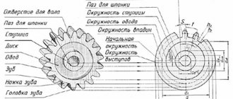
A. Spur wheels
This is the most common type of gear. Their teeth are located in planes perpendicular to the axis of rotation, and the line of contact of the teeth of the gear runs, on the contrary, parallel to this axis. Straight tooth wheels are the least expensive, but they provide a maximum torque that is slightly less than helical or chevron wheels can produce. In addition, gears with such teeth are noisier than gears with more complex teeth.
Care and supervision of gears and gearboxes during operation
When accepting a shift, gears and gearboxes are inspected in cases where this is indicated in the rules for the technical operation of certain types of equipment.
During inspections you must:
- check the oil level in the gearbox and make sure that the level indicator is working properly by test draining the oil through the valve or gearbox plug;
- check for oil leaks and, if necessary, take corrective measures;
- check the flow of oil through the hatch through the splasher;
- check in gearboxes equipped with individual circulation lubrication systems whether enough oil is supplied to the bearings and gear clutches, and, if necessary, adjust its supply, check the tightness of the oil pipeline connections, the pressure and temperature of the oil at the inlet, the pressure difference before and after the cooler filter;
- Check the presence of lubricant on the teeth of open gears and rack and pinion gears, and if necessary, lubricate them.
Maintenance of sliding and rolling bearings, bolted and keyed connections of gearboxes is carried out in accordance with the instructions given in the relevant sections. The oil temperature in gearboxes with spur and bevel gears under normal operating conditions should be no higher than 60 °C, and with worm gears - no more than 75 °C. In gear units subject to radiation heating, the oil temperature may be higher than specified.
When using immersion lubrication, the oil level in gearboxes is maintained so that:
- lubricated wheels of cylindrical gears rotating at a peripheral speed above 3.0 m/s were immersed in oil no more than the height of a tooth;
- bevel wheels at a peripheral speed of up to 5.0 m/s were immersed in oil for the entire length of the tooth;
- in worm gears, when dipping the worm, the latter plunged no more than the height of the turn, and with the upper position of the worm - no more than the height of the worm wheel tooth.
The oil baths of the gearbox are filled with oil of the designated grade and brand, after having previously analyzed the oil. It is prohibited to replace lubricant of one type with lubricant of another type or brand without the permission of the person responsible for the condition of the plant's lubricant facilities.
In all gearboxes with a capacity of over 50 liters, the filled oil is subjected to laboratory analysis at least once every 3-6 months. The oil is considered used and must be replaced with fresh oil if the following signs of aging are detected:
- increasing the acidity of the oil to 5 mg KOH (caustic potassium) per 1 g of oil;
- change in viscosity by 25% of the original value;
- water content in oil over 2%;
- if the aqueous extract is acidic, then more than 0.5%;
- the presence of more than 0.5% mechanical impurities in the oil.
The presence of impurities in the oil that have an abrasive effect is not allowed. When changing the oil, the inner surface of the gearbox housing and the parts located in it must be cleaned of dirt and washed with kerosene.
When jetting oil to the gears (by pouring), it is necessary to ensure the supply of oil at the rate of at least 3.0-4.0 liters per minute for every 100 mm of wheel width. A higher value applies to high-speed (over 15 m/s) and heavily loaded gearboxes. The oil should come out of the nozzle in thin streams covering the entire length of the tooth.
In gearboxes served by a forced circulation lubrication system, the oil is replaced:
- when acidity increases to 4 mg KOH per 1 g of oil;
- when the oil viscosity changes by 15% from the original value;
- in the presence of an acidic reaction of the water extract, if the content of bound moisture (emulsion) in the oil is over 0.1%;
- if the oil contains more than 2% free water or more than 0.5% mechanical impurities.
Oil containing more than 0.2% mechanical impurities or more than 0.5% water is subjected to centrifugation.
In gearboxes exposed to intense heat during operation, the oil is changed at least once a year. The connection points of the gearbox housing, bearing caps and hatch covers for inspecting gears and filling oil must be reliably sealed.
Operation of the mechanism is not allowed if unusual noise, knocking or an increase in oil temperature above the permissible limit is detected in the gearbox. When the gearbox is operating, the noise checked by the ear tube should be insignificant, even, without tapping or crackling. The relationship between the nature of noise and transmission imperfections is shown in Table 6.17.
Table 6.17 – Characteristic noises of gears
| Character of noise | Causes of noise |
| A noise resembling periodic clicking of teeth, especially noticeable from the driven wheel | 1. Poor quality wheel manufacturing - large deviations in the circumferential pitch. 2. Increase in the lateral gap between the teeth against the norm. |
| A sharp metallic grinding, rattling sound that causes vibration of the gearbox housing | 1. Insufficient lateral clearance between gear teeth. 2. Misalignment of a pair of wheels. 3. The presence of sharp edges on the heads of the teeth. 4. The presence of uneven wear on the working profile of the teeth. |
| A noise accompanied by an uneven but continuous knocking sound in the gearing. It can be heard in all places of the gearbox. Vibration of the gearbox housing is felt | 1. Disadvantages of the profile surface of the teeth (banding) |
| Cyclic, rising and falling noise. The frequency of sound changes coincides with wheel revolutions | 1. The presence of eccentricity of the pitch circle of the wheel relative to the axis. 2. The presence of an accumulated group circular step error. |
| Knock in the worm gear | 1. Excessive axial run of the worm. 2. Large production of worm wheel teeth. |
The location of the prints on the tooth heads above the pitch circle indicates an increase in the center-to-center distance, and the location of the prints below the pitch circle indicates that the shafts are too close.
If, when the gear train rotates in the working and opposite directions, both prints are located on the working and non-working profiles at the same edge of the tooth, this indicates that the shafts are not parallel.
If, when the gear drive rotates in two opposite directions, the prints on the working and non-working tooth profiles are located at opposite edges of the tooth, this is a sign of shaft misalignment.
In bevel gears of accuracy class 3, the length of the contact spot must be at least 50% of the tooth length; at the same time, at 30% of their length, touch spots should be along the entire height of the tooth.
In gears of 4th accuracy class, these figures should be equal to 40% and 20%, respectively.
In worm gears, the smallest dimensions of the contact spot when checking for paint or metallic luster must be no less than the following values:
- for gears of 3rd accuracy class - 60% in tooth height, 50% in tooth length;
- for gears of 4th accuracy class - 50% in tooth height, 35% in tooth length.
If uneven wear of the teeth along the length is detected, check the correct position and straightness of the gear shafts.
Design features
There are two types of bevel gearboxes:
The narrow type of gearbox means that the width of the gear will be equal to a quarter of the outer cone distance. Gear ratios are in the range of 3-5, and the number of teeth on the gear is 20-23. For wide-type gearboxes, the wheel width varies from 0.3 to 0.4 outer cone distance. The gear ratios will be 1-2.5, and the number of gear teeth will be from 25 to 28.
The figure below shows a drawing of a bevel gearbox, which shows that the gears contact at a certain angle. The shafts are mounted on single-row roller bearings and are located in a closed housing with a cover. In most cases, the material for the body is steel or cast iron, but there are models made of light alloys. The design uses bevel-type gears with straight or oblique teeth. The use of radial bearings allows them to withstand large axial loads.
According to the type of design, bevel gearboxes can contain one or several stages, with an increase in which a larger number of shafts and bevel pairs will be used. The most common today are single-stage bevel gearboxes. Thanks to two-stage and three-stage units, it is possible to achieve the required torque and reverse movement.
Regardless of the number of stages, rotation is transmitted to the gearbox from the electric motor using a clutch, V-belt or chain drive. The figure below shows the kinematic diagram of a single-stage gearbox.
The conical pair is lubricated using an oil bath. One of the gears is partially immersed in oil and, when rotated, moves some of the oil to the other gear, from which oil drips back into the bath. During operation of the unit, some of the oil gets onto the inner walls of the housing, in which there are technological holes. Through them, oil reaches the bearings and lubricates them.
Classification, main parameters of gearboxes
Depending on the type of gear transmission, gearboxes are cylindrical, bevel, wave, planetary, globoid and worm . Combined gearboxes are widely used, consisting of several types of gears combined in one housing (helical-bevel, helical-worm, etc.).
Structurally, gearboxes can transmit rotation between intersecting, intersecting and parallel shafts. So, for example, spur gearboxes allow you to transmit rotation between parallel shafts, bevel gearboxes - between intersecting ones, and worm gearboxes - between intersecting shafts.