If this parameter is not known to you, then you can calculate it using the formula:
M2 = 9550 x P1 x i x efficiency / 100 x n1
Where: P1 (kW) gearbox input power; i—gear ratio; Efficiency (%) - efficiency factor; n1 (rpm) - revolutions on the input shaft (electric motor shaft).
- Efficiency=98% (for single-stage gearboxes)
- Efficiency=97% (for two-stage gearboxes)
- Efficiency=96% (for three-stage gearboxes)
- Efficiency = 95% (for four-stage gearboxes, as well as for single-stage worm gearboxes)
- Efficiency = 94% (for gearboxes with 5 or more stages, as well as for two-stage worm gearboxes).
Determine the required power P1 (kW) for the gearbox (input power of the gearbox)
If this parameter is not known to you, then you can calculate it using the formula:
P1= M2 x n1 x 100 / 9550 x efficiency
Where: M2 (Nm) gearbox torque; n 1 (rpm) - revolutions on the input shaft (electric motor shaft); Efficiency (%) - efficiency factor.
- Efficiency=98% (for single-stage gearboxes)
- Efficiency=97% (for two-stage gearboxes)
- Efficiency=96% (for three-stage gearboxes)
- Efficiency = 95% (for four-stage gearboxes, as well as for single-stage worm gearboxes)
- Efficiency = 94% (for gearboxes with 5 or more stages, as well as for two-stage worm gearboxes).
Determine the rated power Pe (kW) for the gearbox (rated power of the gearbox)
If this parameter is not known to you, then you can calculate it using the formula:
Where: P1 (kW) - input power of the gearbox; Sf—operation factor (reliability factor).
Determine the required speed n2 (rpm) for your equipment or gear ratio i of the gearbox (revolutions on the output shaft of the gearbox).
If this parameter is not known to you, then you can calculate it using the formula:
n1 (rpm) - revolutions on the input shaft (electric motor shaft); n1 (rpm) - revolutions on the output shaft (gearbox shaft).
Calculate the required radial load Fq (N) on the output shaft of the gearbox (depending on the type of connection of the gearbox to the equipment).
The radial load on the gearbox shaft can be calculated using the formula:
- Fq = 2100 x M2 / D gear (working angle – 20 degrees)
- Fq = 2100 x M2 / D chain drive (at low speeds z > 17)
- Fq = 2500 x M2/D toothed belt drive
- Fq = 5000 x M2/D V-belt drive
- Fq = 5000 x M2/D belt drive via tensioner pulley
Where: Fq (N) - radial load on the gearbox shaft; M2 (Nm) — gearbox torque; D (mm) - diameter of gear or pulley; When choosing a gearbox, it is necessary to take into account that:
Any movable connection that transmits force and changes the direction of movement has its own technical characteristics. The main criterion that determines the change in angular velocity and direction of movement is the gear ratio. Inextricably linked with it is a change in force—the gear ratio. It is calculated for each transmission: belt, chain, gear when designing mechanisms and machines.
Before you find out the gear ratio, you need to count the number of teeth on the gears. Then divide their number on the driven wheel by the same indicator on the drive gear. A number greater than 1 means an overdrive gear, increasing the number of revolutions and speed. If less than 1, then the transmission is downshifting, increasing power and impact force.
General definition
A clear example of changing the number of revolutions is most easily observed on a simple bicycle. A man pedals slowly. The wheel rotates much faster. The change in the number of revolutions occurs due to 2 sprockets connected in a chain. When the large one, which rotates with the pedals, makes one revolution, the small one, standing on the rear hub, rotates several times.
Torque transmissions
The mechanisms use several types of gears that change torque. They have their own characteristics, positive qualities and disadvantages. Most common transmissions:
Belt drive is the simplest to implement. It is used when creating homemade machines, in machine tools to change the speed of rotation of the working unit, in cars.
The belt is tensioned between 2 pulleys and transmits rotation from the driver to the driven. Performance is poor because the belt slides on a smooth surface. Thanks to this, the belt assembly is the safest way to transmit rotation. When overloaded, the belt slips and the driven shaft stops.
The transmitted number of revolutions depends on the diameter of the pulleys and the coefficient of adhesion. The direction of rotation does not change.
The transitional design is a belt gear drive.
There are protrusions on the belt and teeth on the gear. This type of belt is located under the hood of the car and connects the sprockets on the axles of the crankshaft and carburetor. When overloaded, the belt breaks, since it is the cheapest part of the unit.
The chain consists of sprockets and a chain with rollers. The transmitted speed, force and direction of rotation do not change. Chain drives are widely used in transport mechanisms and on conveyors.
Gear Characteristics
In a gear drive, the driving and driven parts interact directly through the meshing of teeth. The basic rule for the operation of such a node is that the modules must be identical. Otherwise, the mechanism will jam. It follows that the diameters increase in direct proportion to the number of teeth. Some values can be replaced by others in calculations.
Modulus is the size between identical points of two adjacent teeth.
For example, between axes or points on an involute along the center line. The module size consists of the width of the tooth and the gap between them. It is better to measure the module at the point of intersection of the base line and the axis of the tooth. The smaller the radius, the more the gap between the teeth along the outer diameter is distorted; it increases towards the top from the nominal size. Ideal involute shapes can practically only be found on a rack. Theoretically, on a wheel with a maximally infinite radius.
The part with fewer teeth is called a gear. Usually it is leading, transmitting torque from the engine.
The gear wheel has a larger diameter and is driven in a pair. It is connected to the working unit. For example, it transmits rotation at the required speed to the wheels of a car or the spindle of a machine tool.
Typically, gearing reduces the number of revolutions and increases power. If in a pair there is a part with a larger diameter, the drive gear, at the output, the gear has a greater number of revolutions and rotates faster, but the power of the mechanism decreases. Such gears are called downshifts.
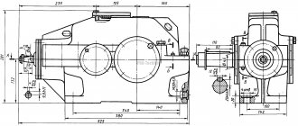
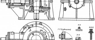
Calculation of gear housing elements
Gearbox housing wall thickness
= 0.025+ 1=5 mm
We round the resulting value to a whole number, taking into account that the wall thickness must be at least 8 mm. Let's accept
= 8
Foundation bolt diameter
d
b1 = 0.036
+ 12 = 17.76 mm
, round the calculated value to the standard thread diameter:
The diameters of the bolts securing the housing cover to the base are:
After rounding to standard values: d
b2 = 16 mm,
d
b3 =12 mm
Distance from the inner wall of the housing to the edge of the paw
L
1= 3 +
+ b
1 =51 mm
where b
1 = 40 mm, determined from table.
5 depending on the diameter of the bolt d
b1.
Distance from the inner wall of the housing to the axis of the foundation bolt
P
1 = 3 +
+ a
1 = 28 mm
where a
1 = 17 mm, determined from table.
5 depending on the diameter of the bolt d
b1.
Distance from the inner wall of the housing to the axis of the bolt at the bearing
P
2= 3 +
+ a
2= 24 mm
where a
2 = 13 mm, determined from table.
5 depending on the diameter of the bolt d
b2.
Distance from the inner wall of the housing to the axis of the foundation bolt
P
3= 3 +
+ a
3= 21 mm
where a
3 = 9 mm, determined from table.
5 depending on the diameter of the bolt d
b3.
h=
2.5
=20 mm
h
1
=
1.6
= 14 mm
Minimum distance from the circle of the gear vertices to the wall of the gearbox housing
f
= 1.2
=10 mm
C
=
= 8
To reduce power losses due to friction and reduce the wear rate of rubbing surfaces, as well as to protect them from seizing, corrosion and better heat removal, the rubbing surfaces of parts must have reliable lubrication.
How to calculate gear ratio
The gear and wheel have a different number of teeth with the same module and proportional diameters. The gear ratio shows how many revolutions the driving part will make to turn the driven part a full circle. Gears have a rigid connection. The transmitted number of revolutions in them does not change. This negatively affects the operation of the unit under conditions of overload and dust. The tooth cannot slip like a belt on a pulley and breaks.
Calculation without resistance
When calculating the gear ratio, the number of teeth on each part or their radii are used.
Where u12 is the gear and wheel gear ratio;
Z2 and Z1 are the number of teeth of the driven wheel and drive gear, respectively.
The “+” sign is placed if the direction of rotation does not change. This applies to planetary gearboxes and gears with teeth cut along the inner diameter of the wheel. If there are parasites - intermediate parts located between the drive gear and the ring gear, the direction of rotation changes, as with an external connection. In these cases, “–” is placed in the formula.
When two parts are externally connected by means of a parasite located between them, the gear ratio is calculated as the ratio of the number of teeth of the wheel and gear with the “+” sign. The parasite does not participate in the calculations, it only changes the direction, and accordingly the sign in front of the formula.
Calculation method
Is it possible to find out the gear ratio of an unknown car without disassembling the gearbox? It turns out there is such a way. To do this, the axis on which the gearbox is installed is hung on supports. The position of the drive shaft and wheels is remembered. It is convenient to do this with simple marks. Then the wheels are turned until the marks coincide again, counting the number of revolutions of the wheels and shaft separately. It is more convenient to carry out this procedure with an assistant.
After obtaining experimental data, the number should be calculated by dividing the number of shaft revolutions by the number of wheel revolutions. The accuracy of this method is approximate and is improved only by being careful when counting and combining marks.
Gear ratio
The value of the gear ratio is the same as the gear ratio. The magnitude of the angular velocity and moment of force changes in proportion to the diameter, and according to the number of teeth, but has the opposite meaning.
The greater the number of teeth, the lower the angular velocity and the impact force - power.
With a schematic representation of the magnitude of force and displacement, the gear and wheel can be represented as a lever with a support at the point of contact of the teeth and sides equal to the diameters of the mating parts. When shifted by 1 tooth, their extreme points travel the same distance. But the rotation angle and torque on each part are different.
For example, a 10-tooth gear rotates 36°. At the same time, the part with 30 teeth moves by 12°. The angular velocity of a part with a smaller diameter is much greater, 3 times. At the same time, the path that a point travels on the outer diameter has an inversely proportional relationship. On the gear, the movement of the outer diameter is less. The moment of force increases inversely with the displacement ratio.
The torque increases with the radius of the part. It is directly proportional to the size of the impact arm - the length of the imaginary lever.
The gear ratio shows how much the moment of force has changed when it is transmitted through the gearing. The digital value matches the transmitted speed.
The gear ratio is calculated using the formula:
where U12 is the gear ratio relative to the wheel;
ω1 and ω2 – angular velocities of the leading and driven element of the connection;
The ratio of angular speeds can be calculated through the number of teeth. In this case, the direction of rotation is not taken into account and all numbers with a positive sign are not taken into account.
The gear drive has the highest efficiency and the least protection against overload - the force application element breaks, and you have to make a new expensive part with complex manufacturing technology.
If you find an error, please select a piece of text and press Ctrl+Enter.
Purchasing a motor gearbox is an investment in technical and technological business processes, which must not only be justified, but also pay off. And the payback largely depends on the choice of gear motor for specific purposes. It is carried out on the basis of a professional calculation of power, dimensions, productive efficiency, and the required load level for specific purposes of use.
To avoid mistakes that can lead to early wear of the equipment and costly financial losses, the calculation of the geared motor should be carried out by qualified specialists. If necessary, experts can conduct this and other studies to select a gearbox.
Checking the calculations
If all the calculations made turned out to be correct, and the values we calculated converge, then three conditions must be met. Firstly,
where Tnom is the rated torque obtained on the output shaft. This value can be found in the technical description of the gearbox.
In this formula, Fnom is taken by analogy from the technical specification of the product, and Fout.calc is taken from the values we obtained (formula 6).
P input calculation is the power of the electric motor, which is calculated by the formula:
The efficiency of the gearbox depends on its type and number of stages. Thus, for a cylindrical gearbox with one stage, the efficiency will be 0.99, with two – 0.98, with three – 0.97, with four – 0.95. A single-stage bevel gearbox has an efficiency of 0.98, a two-stage gearbox has an efficiency of 0.97. The efficiency of a bevel-helical gearbox is determined by multiplying the values given for the bevel and helical gearboxes separately. The efficiency of worm gearboxes can be viewed in the technical description, and each gear ratio will have its own specific value.
Source
Selection by main characteristics
Long service life while ensuring the specified level of performance of the equipment with which the geared motor operates is a key benefit when choosing the right drive. Our long-term practice shows that when determining requirements, we should proceed from the following parameters:
- minimum 7 years of maintenance-free operation for the worm mechanism;
- from 10–15 years for a cylindrical drive.
When determining the data for submitting an order for the production of a geared motor, the key characteristics are:
- power of the connected electric motor,
- rotation speed of the moving elements of the system,
- motor power type,
- operating conditions of the gearbox – operating mode and loading.
When calculating the power of an electric motor for a gearmotor, the performance of the equipment with which it will work is taken as a basis. The performance of a gear motor largely depends on the output torque and the speed of its operation. Speed, like efficiency, can change with voltage fluctuations in the engine power supply system.
The speed of the motor gearbox is a dependent quantity that is influenced by two characteristics:
- gear ratio;
- frequency of rotational movements of the motor.
Our catalog contains gearboxes with different speed parameters. Models are available with one or more speed settings. The second option provides for a system for regulating speed parameters and is used in cases where, during operation of the gearbox, periodic changes in speed modes are necessary.
Where to buy a worm gearbox
If you are planning to buy a worm gearbox for the long term at a reasonable price, we have something to offer you. PTC "Privod" has been supplying this equipment throughout Russia and the CIS countries for many years.
We offer only highly reliable quality units at an effective manufacturer's price with long-term service guarantees. We provide full support for your order - from assistance in constructing a system of requirements to selecting a worm gearbox that meets the stated operating conditions.
Selection by type of gearbox for drive
Professional calculations for the purpose of selecting a gearbox always begin with the elaboration of the drive (kinematic) diagram. It is this that underlies the compliance of the selected equipment with the conditions of future operation. According to this diagram, you can choose the class of gear motor. The options are as follows.
- Worm mechanism:
- single-stage transmission, input shaft at right angles to the output shaft (crossed position of the input shaft and output shaft);
- two-stage mechanism with the input shaft located parallel or perpendicular to the output shaft (the axes can be located vertically/horizontally).
- Helical gear motor :
- with a parallel position of the input shaft and output shaft and horizontal placement of the axes (the output shaft and the input organ are in the same plane);
- with the axes of the input and output shafts placed in the same plane, but coaxially (located at any angle).
- Conical-cylindrical. In it, the axis of the input shaft intersects with the axis of the output shaft at an angle of 90 degrees.
- Cylindrical and bevel motor gearboxes , having similar weight and dimensions to a worm drive, demonstrate higher efficiency.
- The load transmitted by a spur gearbox is 1.5–2 times higher than that of a worm gearbox.
- The use of bevel and cylindrical gears is only possible when placed horizontally.
The position of the output shaft is of key importance when choosing a gearmotor. When taking an integrated approach to device selection, the following should be taken into account:
Equipment selection
This must be understood: even in devices of identical configuration/design, the ratio of the rotation speed of the input shaft and the output shaft may differ. To make the right choice, it is important to know how to calculate the gear ratio of a gear motor. Although there is another way - check the data directly with the manufacturer.
Production engineers know everything about the characteristics of gear equipment and are happy to help the customer select a mechanism that optimally meets the needs of the production site. Professional calculations and comprehensive information support are provided free of charge. Experts will tell you how to determine the gear ratio and place an order. They will also help you calculate the cost and guide you on the delivery time.
Classification by number of stages and type of transmission
| Gearbox type | Number of steps | Transmission type | Axes location |
| Cylindrical | 1 | One or more cylindrical | Parallel |
| 2 | Parallel/coaxial | ||
| 3 | |||
| 4 | Parallel | ||
| Conical | 1 | Conical | Intersecting |
| Conical-cylindrical | 2 | Conical Cylindrical (one or more) | Intersecting / Crossing |
| 3 | |||
| 4 | |||
| Worm | 1 | Worm (one or two) | Crossbreeding |
| 2 | Parallel | ||
| Cylindrical-worm or worm-cylindrical | 2 | Cylindrical (one or two) Worm (one) | Crossbreeding |
| 3 | |||
| Planetary | 1 | Two central gears and satellites (for each stage) | Coaxial |
| 2 | |||
| 3 | |||
| Cylindrical-planetary | 2 | Cylindrical (one or more) Planetary (one or more) | Parallel/coaxial |
| 3 | |||
| 4 | |||
| Cone-planetary | 2 | Conical (single) Planetary (one or more) | Intersecting |
| 3 | |||
| 4 | |||
| Worm-planetary | 2 | Worm (one) Planetary (one or more) | Crossbreeding |
| 3 | |||
| 4 | |||
| Wave | 1 | Wave (one) | Coaxial |
Gear ratio
The gear ratio is determined using a formula of the form:
- nin – input shaft revolutions (electric motor characteristics) per minute;
- nout – the required number of revolutions of the output shaft per minute.
The resulting quotient is rounded to the gear ratio from the standard range for specific types of gearmotors. The key condition for successful selection of an electric motor is the limitation on the input shaft rotation speed. For all types of drive mechanisms it should not exceed 1.5 thousand revolutions per minute. The specific frequency criterion is indicated in the technical characteristics of the engine.
Procedure for selecting a worm gearbox
Among the advantages of this unit is the reasonable price of the worm gearbox . But even taking this into account, the selection must be very careful. In order to buy equipment that will optimally fit into the technical equipment program used, you need to understand the basic parameters for choosing a worm gearbox. This system for calculating parameters for determining price contains the following characteristics:
- gear ratio;
- efficiency;
- number of steps;
- planned launch time;
- overall dimensions of the structure.
Determination of gear ratio
The selection of a worm gearbox begins with the calculation of the gear ratio - the ratio of the teeth of the driven gear to the number of teeth of the drive worm. The multiplicity of increase in torque when the worm moves depends on this.
To calculate the gear ratio (required) in order to correctly select a worm gearbox, a formula of the form is used:
- N in. – these are the de facto revolutions of the electric motor input shaft (according to the passport, quantity per minute);
- N out. – the required number of revolutions of the low-speed output shaft per minute.
Results must be rounded. After which you can buy a model, guided by the table of gear ratios for different variations of mechanisms.
Calculation of the number of steps
Calculation of the gear ratio is also key when determining the required number of steps. To accomplish the last task, it is necessary to select a system according to the obtained relationship from the table below.
| Worm gear selection | Gear ratios |
| single stage | 8–80 |
| two-stage | 100–4000 |
Selection of worm gear by size
Competent selection of a worm gearbox based on dimensional parameters requires matching the power parameters and engine speed with the type of drive mechanism. To decide which size you need to buy, use the formula:
- P – performance of the electric motor used, taken in kW;
- U is the calculated gear ratio;
- N – efficiency, according to technical characteristics and calculation results;
- K – utilization/operation coefficient, taken depending on the operating conditions of the worm gearbox , according to the table (it is presented below);
- N in. – nameplate number of engine revolutions.
| Mode of use (according to GOST 21354-87, as well as GosTechNadzor standards) | PV (%) | K | |
| Continuous | 100 | 0,7 | |
| I | Heavy | >63 | 0,8 |
| II | Average | Duration of operation The switching time is calculated as follows:
Important condition: the resulting torque must not exceed the rated torque. The latter is indicated in the passport (technical characteristics of the worm gearbox ). This is necessary for long-term operation of the mechanism shafts (to avoid differences between the loads applied de facto and those provided for in the passport). |
Range of gear ratios for gearboxes
| Gearbox type | Gear ratios |
| Worm single stage | 8-80 |
| Worm two-stage | 25-10000 |
| Cylindrical single stage | 2-6,3 |
| Cylindrical two-stage | 8-50 |
| Cylindrical three stage | 31,5-200 |
| End-cylindrical single-stage | 6,3-28 |
| End-cylindrical two-stage | 28-100 |
Power
During rotational movements of the working parts of the mechanisms, resistance arises, which leads to friction - abrasion of the units. With the right choice of gearbox in terms of power, it is able to overcome this resistance. Therefore, this point is of great importance when you need to buy a gearmotor for long-term purposes.
The power itself - P - is calculated as a quotient of the force and speed of the gearbox. The formula looks like this:
- where: M – moment of force;
- N – revolutions per minute.
To select the desired gearmotor, it is necessary to compare the power data at the input and output - P1 and P2, respectively. output power of the geared motor
- where: P – gearbox power; Sf is the operating factor, also known as the service factor.
At the output, the power of the gearbox (P1 > P2) should be lower than at the input. The norm of this inequality is explained by the inevitable losses in performance during engagement as a result of friction between parts.
When calculating capacity, it is imperative to use accurate data: due to different efficiency indicators, the probability of selection error when using approximate data is close to 80%.
Gearbox torque
Output shaft torque [M2]—torque on the output shaft. The rated power [Pn], the safety factor [S], the estimated service life (10 thousand hours), and the efficiency of the gearbox are taken into account.
Rated torque [Mn2] - the maximum torque that ensures safe transmission. Its value is calculated taking into account the safety factor - 1 and the service life - 10 thousand hours.
Maximum torque [M2max] - the maximum torque that the gearbox can withstand under constant or changing loads, operation with frequent starts/stops. This value can be interpreted as the instantaneous peak load in the operating mode of the equipment.
Required torque [Mr2] - torque that meets customer criteria. Its value is less than or equal to the rated torque.
Design torque [Mc2] - the value required to select a gearbox. The estimated value is calculated using the following formula:
Mc2 = Mr2 x Sf <= Mn2
where Mr2 is the required torque; Sf—service factor (operational factor); Mn2 is the rated torque.
Efficiency calculation
The efficiency of a gearmotor is the quotient of the division of power at the output and at the input. Calculated as a percentage, the formula looks like:
When determining efficiency, one should rely on the following points:
- the efficiency value directly depends on the gear ratio: the higher it is, the higher the efficiency;
- During operation of the gearbox, its efficiency may decrease - it is affected by both the nature or operating conditions, as well as the quality of the lubricant used, compliance with the scheduled repair schedule, timely maintenance, etc.
Gearbox calculation
The reliability of the gearbox and its service life are determined by the correct choice you made when purchasing the equipment. Breakdown of the gearbox, its malfunction and, as a result, additional financial costs - all this may indicate various errors that were made when calculating the gearbox. In addition, a correctly selected gearbox has a significantly longer service life: for spur gearboxes it is 10-15 years, and for worm gearboxes it is 7-9 years. Consequently, the most rational decision when choosing such equipment is to entrust the calculation of the gearbox to highly qualified specialists who will not forget to take into account factors such as the degree of permissible heating or the temperature conditions of operation of the gearbox. Our employees will be happy to help you make the right choice and select the gearbox that is suitable for your specific purposes. To do this, you can use the online consultation function, order a free call or leave a request by mail. Receive professional advice from our specialists in the way that is convenient for you!
There are three main steps when calculating a gearbox. Necessary:
Reliability indicators
The table below shows the service life standards for the main parts of the gearmotor during long-term operation of the device with constant activity.
Resource
| Index | Gearbox type | Value, h |
| 90% service life of shafts and gears | Cylindrical, planetary, conical, conical-cylindrical | 25000 |
| 90% bearing life | Worm, wave, globoid | 10000 |
| Cylindrical, planetary, conical, conical-cylindrical | 12500 | |
| Worm | 5000 | |
| Globoid, wave | 10000 |
Determining the oil level.
In helical gearboxes:
When dipping wheels into an oil bath, m≤ hм≤0.25d2, where m is the engagement module; with the lower gear position hм=(0.1....0.5)d1, while hmin=2.2m. It is desirable that the oil level passes through the center of the lower rolling element of the bearing (ball or roller).
When the spur gear is located at the bottom and the rotation speed is high, to reduce heat generation and power loss, the oil level is lowered so as to remove the gear from the oil bath. In this case, for lubrication, sprinklers are installed on the gear.
Buy gear motor
PTC "Privod" is a manufacturer of gearboxes and geared motors with different characteristics and efficiency, which is not indifferent to the payback indicators of its equipment. We are constantly working not only to improve the quality of our products, but also to create the most comfortable conditions for purchasing them for you.
To minimize selection errors, we offer our customers an intelligent configurator. To use this service you do not need any special skills or knowledge. The tool works online and will help you decide on the optimal type of equipment. We will offer the best price for any type of gear motor and full support for its delivery.
Types of explosion-proof design
There are 3 main categories of gearboxes and geared motors according to explosion protection class:
- E – devices with an increased degree of security. Suitable for use in any conditions, including in emergency situations. Due to their high tightness, the housings are suitable for use in environments with explosive and flammable gases and gas-air mixtures without the risk of ignition of the latter;
- D – gearmotors with an explosion-proof housing, indestructible in the event of an explosion of the unit itself. They are distinguished by the complete tightness of the shell and safety, which allows them to be used in environments of any explosive gases and mixtures, as well as at extremely high operating temperatures;
- I – devices with increased intrinsic safety. They imply the support of explosion-proof current in the supply circuit in accordance with specific production conditions.