The design of a bevel-helical gearbox plays an important role in its design, and ordinary industrial engineers cannot always perform the corresponding calculations.
Experts can help with solving such problems. The equipment itself can be horizontal or vertical. The main difficulty in the schemes is represented by several types of transmissions. The reversible type of drive can also complicate the calculations.
Article navigation
What is calculated using the kinematic scheme?
What is shown on the kinematic diagram of a bevel-helical gearbox?
What is the design of a bevel-helical gearbox?
Description of the design.
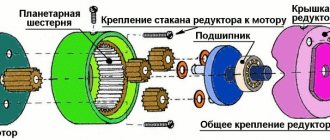
The bevel-cylindrical gearbox consists of a pair of bevel wheels with circular teeth (high-speed stage) and a pair of cylindrical helical wheels. The cast iron body has a connector in the horizontal plane. High-speed shaft supports: radial ball bearing to absorb the greatest radial reaction, two angular contact bearings with tapered rollers to absorb axial loads.
Tapered roller bearings are adjusted using a set of shims between the cover and the cups. The engagement is adjusted by a set of gaskets between the housing and the cup on the high-speed shaft and a set of gaskets between the covers and the housing on the intermediate shaft. The gears in the gearbox are lubricated by immersing the wheels in oil; bearings - by splashing oil. Oil is supplied to the drive shaft bearings through grooves made in the plane of the gear housing connector.
Design features
There are two types of bevel gearboxes:
- narrow;
- wide.
The narrow type of gearbox means that the width of the gear will be equal to a quarter of the outer cone distance. Gear ratios are in the range of 3-5, and the number of teeth on the gear is 20-23. For wide-type gearboxes, the wheel width varies from 0.3 to 0.4 outer cone distance. The gear ratios will be 1-2.5, and the number of gear teeth will be from 25 to 28.
The figure below shows a drawing of a bevel gearbox, which shows that the gears contact at a certain angle. The shafts are mounted on single-row roller bearings and are located in a closed housing with a cover. In most cases, the material for the body is steel or cast iron, but there are models made of light alloys. The design uses bevel-type gears with straight or oblique teeth. The use of radial bearings allows them to withstand large axial loads.
According to the type of design, bevel gearboxes can contain one or several stages, with an increase in which a larger number of shafts and bevel pairs will be used. The most common today are single-stage bevel gearboxes. Thanks to two-stage and three-stage units, it is possible to achieve the required torque and reverse movement.
Regardless of the number of stages, rotation is transmitted to the gearbox from the electric motor using a clutch, V-belt or chain drive. The figure below shows the kinematic diagram of a single-stage gearbox.
The conical pair is lubricated using an oil bath. One of the gears is partially immersed in oil and, when rotated, moves some of the oil to the other gear, from which oil drips back into the bath. During operation of the unit, some of the oil gets onto the inner walls of the housing, in which there are technological holes. Through them, oil reaches the bearings and lubricates them.
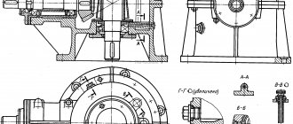
Versions of the high-speed shaft of a bevel-cylindrical three-stage gearbox.
Designs of the high-speed shaft of a bevel-helical gearbox with a vertical arrangement of the high-speed shaft are shown in Fig. 13.
Rice. 1 - the flange electric motor is connected to the gear shaft by an elastic coupling built inside the gear shaft. The design is compact, but difficult to manufacture. The glass for mounting the engine and the gear shaft is common.
Rice. 2 - the electric motor shaft is inserted inside the gear shaft. The design is compact, but has the following disadvantages: by centering the engine with its flange in the hole of the glass, specially designed for this purpose, it is necessary to provide a gap in the connection, which will adversely affect the operation of the keyed connection of these shafts.
Rice. 3 - the electric motor is attached to a glass, which is centered on the gearbox housing. One gear shaft support secures the shaft from axial displacement in two directions, the second support is “floating”. Lubricant is supplied to the upper bearings using a grease nipple.
Related Pages
- Kinematic diagrams of gearboxes
- Gearbox with vertical shafts
- Gearbox with two high-speed shafts.
- Two-stage gearbox
- Two-stage coaxial gearbox
- Design options for shaft supports of a cylindrical two-stage coaxial gearbox
- Gearbox with torsion shafts
- Two-stage, three-flow coaxial gearbox
- Coaxial cylindrical gearbox with internal gearing of low-speed stage
- Geared motor MTs2S-125
- Cylindrical gearbox Ts2-160
- Two-stage cylindrical gearbox 1Ts2U.
- Gearbox Ts2-200.
- Special gearbox
- Gearbox Ts3KF-100
- Reducer RTC-500.
- Three-stage gearbox
- Reducer RCT-1015.
- Bevel gearbox K-125.
- Bevel gearbox
- Worm gearbox.
- Helical worm gear motor.
- Helical-worm gearbox.
- Two-stage worm gearbox.
What is the design of a bevel-helical gearbox?
All drawings can be divided into structural, functional, and fundamental. Customers often mistakenly assume that they are the same, but in fact they are not. Functional drawings show all the elements involved in the transmission of torque and the connections between them. Technical specifications are indicated next to the graphic symbols.
The schematic drawings contain elements involved in kinematic processes. They are needed in order to understand the principles of operation of the product. Structural drawings show the main functional parts of the equipment. They provide a visual representation of how different parts in the designed device will interact.
Which three-stage gearbox should I choose?
When choosing a cylindrical three-stage gearbox, it is necessary to take into account the type of transmission and its technical data:
- gear ratios (including actual) - devices are divided into groups and standard sizes;
- continuous torque in the presence of a stable long-term load;
- permissible torque during short-term operation;
- maximum radial load;
- Efficiency (usually within 0.96);
- weight of the unit (measured in kg).
Gearboxes of the CTND type have 2 lines of engagement and are designed for drives of elevators and machines used in the mining and coal industries. They are suitable for horizontal placement.
When choosing a gearbox, the type of shaft used in the mechanism must correspond.
It can be high-speed or low-speed. The appropriate standard size affects the dimensions of the product and its price. It is better to entrust the calculation of the optimal option to professionals; we will first provide them with all the necessary initial data regarding the mechanism or motor where the equipment will be installed. When using reverse mode in special duty mechanisms, the permissible torque on the low-speed shaft must be reduced by at least 30%.
Gear housings
In mass production, a helical gearbox is usually equipped with a cast housing of a standardized size using cast iron or cast steel. The specifications for these materials are given in the relevant regulatory industry documents and GOST. In cases where a light weight structure is required, light alloy housings are used.
In piece production, welded housings are most often used, which makes it possible to implement design solutions, the calculation and design of which were carried out on an individual order.
On the gearbox housings, as a rule, there are places for fastening in the form of “ears” and/or “paws”, with the help of which they can be moved and secured at the installation site, using the assembly drawing for the car. Seals are installed on the output part of the shafts to prevent oil leakage. On the outside of the gearbox housing, there may be additional structural elements that prevent an increase in the internal pressure of the gearbox, which can occur when it heats up during operation.
Where and for what are single-stage horizontal gearboxes used?
They find their use:
- where constant or variable load, reversible and one direction is required;
- to ensure continuous work or with short breaks;
- to ensure rotation of the shafts in different directions.
They cannot or are dangerous to use if the shaft rotation speed exceeds 1800 revolutions per minute, as well as when the air dust content is higher than 10 mg per cubic meter. meter and atmosphere of the first and second types in accordance with GOST 15150-69.
Main types of gearboxes
They share:
- By type of transfer connection to:
- toothed;
- worm;
- combined.
- Depending on the shape of the gears on;
- cylindrical;
- conical and others.
- According to the location of the shafts in space on:
- vertical;
- horizontal.
- Depending on the characteristics of the kinematic system that underlies a particular mechanism on:
- expanded;
- with double stage, etc.
- By the number of steps:
- single stage;
- two-stage.
Operating principle of a single-stage gearbox
It's simple enough to understand. In such a mechanism, through a smaller sprocket located on one shaft to a larger one installed on another shaft, rotational motion is transmitted through the teeth. The effect of reducing the number of revolutions per minute is achieved due to the difference in the diameter of the sprockets. The length of the circle that the first one outlines during movement is significantly less than the one that the second one outlines, so the large asterisk rotates more slowly.
In this case, reverse-acting devices are created that do not reduce the number of revolutions per unit of time, but rather increase them.
This type of gearbox is the simplest. It differs from others in that motion is transmitted through one link, and not through several, while the incoming and outgoing rotations have opposite directions.
Torque can also be transmitted using a worm mechanism, but the gear ratio is affected by the diameter of the “worm”.
What does the gearbox consist of?
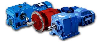
It consists of a welded steel or cast iron body. It houses shafts, axles, gears, worm gears, bearings and other elements. Some gearboxes contain special devices that provide lubrication of gearbox elements. For example, it may be equipped with an oil pump or a device that provides cooling for this unit (a coil with coolant is often mounted in a worm gearbox).
Gearboxes are different. At the same time, they differ not only in types, but also in individual characteristics, so gearboxes are designed for specific equipment or unit, depending on the need, gear ratio and torque that needs to be transmitted to the receiving device.
Advantages and disadvantages
The design of bevel gearboxes is similar to cylindrical gearboxes, so their advantages and disadvantages are similar. The main advantage of a bevel gearbox is the arrangement of gears or couplings at an angle. This makes it possible to transmit rotation from the drive shaft to the driven shaft, located at an angle of 90 degrees to the first.
Another important advantage of such a device is its immunity to variable and short-term loads. For this reason, they are often used in production processes with frequent starts.
As mentioned above, bevel gearboxes have a structure similar to cylindrical gearboxes, but they have their own disadvantages. These include:
- lower efficiency;
- Wheel seizures occur more frequently.
Despite the fact that the efficiency of such a unit is 10% lower and cases of gear jamming are possible, bevel gearboxes are in great demand and have found application in many areas.