Straight and helical racks
Spur gear racks are used for low to medium speed operation. In turn, a helical rack is used where high precision of movement and high or medium operating speeds are required.
Spur gear-rack transmissions
Spur gear-rack transmissions can not only be made of steel, but also cast from cast iron. This manufacturing method is practiced where there is no need for high displacement accuracy, but the mechanism is operated in conditions of heavy dust or high temperatures. In this case, the rack and wheel have a rough surface and produce a lot of noise when moving. This type of rack and pinion transmission is used mainly in metallurgy, and the rack is installed tooth down, and the drive and gear are installed in a specially equipped pit.
Helical rack and pinion pair
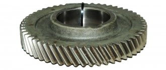
When engaged, a helical rack and pinion pair is capable of transmitting more force than a straight toothed one, and during operation it produces less noise. The manufacturing of helical rack and pinion requires high precision, and the installation requires fine adjustments. Initially, the gear has an increased contact area due to the location of the teeth, but as their surface wears, the center-to-center distance must be shifted. Otherwise, the load shifts when the angle changes, and the process of destruction of the gear proceeds very quickly.
Manufacturing
Blanks for gear wheelsets can be made by casting or stamping. Subsequently, they are subjected to additional processing, and teeth are cut. For this purpose, disc and finger cutters and shaped grinding wheels are used.
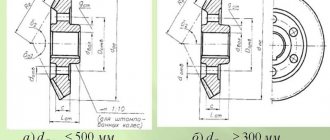
The bevel type gear mechanism cannot be manufactured by finishing cutting with a milling cutter or grinding, since the profile of the projections and valleys is not constant. This can only be done at the initial stage of roughing. Further finishing is carried out on machines during the process of running in with gearing. For this, a pair of wheels made of high-strength material that follows the main profile is used. It acts as a cutting tool.
Carbon steels are subjected to hardening, carburization, nitriding or cyanidation. For non-critical components, heat treatment can be carried out after cutting the teeth. High precision wheelsets require additional finishing grinding or running in.
Basic parameters of gear-rack gears
For a rack and pinion transmission, the main dimensional parameter is the pitch (distance) between the rack teeth. This value can be calculated in two ways: using the modular system or the metric system. The distance between the rack teeth in a modular system should be calculated using the formula m = D/z, in which the letter m denotes the module of the rack-gear pair, the letter z the number of gear teeth, and the letter D the pitch diameter of the gear. In the latter case, we mean the diameter of the circle that passes through the half-height of the gear tooth. For uncorrected gears, the pitch and initial circles coincide.
The value of the rack-and-pinion transmission module is fractional. It represents an infinite decimal fraction, and the rounded value of this value is used in the rack and pinion calculation process. Generally accepted values for this parameter can range, as a rule, from 0.5 to 25 mm. The distance between the rack teeth in the metric system is measured in millimeters. For rack and pinion gears, each manufacturer has a line of standard sizes, which, however, does not limit the possibility of ordering rack and pinion gears with non-standard parameters at domestic metalworking and machine-building enterprises.
It is worth considering that the modular selection system is used in cases where the rack is matched to the gear. This procedure is practiced mainly in production, where complete drives are produced - rack + pinion + serial geared motor. If the transmission production technology involves selecting a gear for the rack, the metric system is used. Typically, this method is used in the process of searching for original design solutions, implementing know-how, designing non-standard equipment, devices, machines and mechanisms.
Literature
- Ed.
Skorokhodova E. A. General technical reference book. - M.: Mechanical Engineering, 1982. - P. 416. - Gulia N.V., Klokov V.G., Yurkov S.A.
Machine parts. - M.: Publishing House, 2004. - P. 416. - ISBN 5-7695-1384-5. - Bogdanov V.N., Malezhik I.F., Verkhola A.P. et al.
Reference Guide to Drawing. - M.: Mechanical Engineering, 1989. - P. 438-480. — 864 p. — ISBN 5-217-00403-7. - Kravchenko A. I., Bovda A. M. Gear transmission with magnetic coupling. Patent of Ukraine No. 56700. Bulletin. No. 2, 2011. - F16H49/00.
- Ivashov E.I., Kuznetsov P.S., Stepanchikov S.V. Gear transmission with magnetic interaction of teeth. - 2011. - (USSR Author's Certificate No. 107309).
- Ganzburg L.F., Fedotov A.V. Design of electromagnetic and magnetic mechanisms: Directory - L.: Mashinostroenie, 1980. - 364 p.
Manufacturing of gears and racks
The calculation procedure and basic characteristics of rack-and-pinion gear mechanisms are regulated by the following standards: for gears GOST 16532-70, for gear racks GOST 13755-81, for rack tolerances GOST 10242-81. The degree of accuracy when designing a rack and pinion transmission depends on the purpose of the mechanism (kinematic or power) and the speed of rotation of the gear wheel. The strength calculation is carried out using the drive gear; the calculation is guided by the requirements of GOST 21354-87. In the manufacture of rack and pinion gears, the deviations in the dimensions of the rack and wheel are specified in GOST 2789-73, and the roughness standards are specified in GOST 2.309-73.
Materials
Racks and pinions are usually made of steel. At the same time, for mechanisms that during operation do not have to experience high loads and operate at high speed, it is enough to choose good quality carbon steel - for example, steel grades 35, 45, 50. Low-alloy steels 35ХГС, 40Х, 40ХН, 40ХНТ and steel grades are also suitable 40G2, 50G - their composition has an increased manganese content. If the rack-and-pinion transmission will be operated under increased loads, during the production process the product is subjected to thermal and chemical-thermal treatment in order to increase its strength characteristics. In addition, structural and alloy steels can be used.
Precision and strength
When choosing a material and additional processing methods for a rack and pinion transmission, it is recommended to strive to ensure that in a gear-rack pair the hardness of the lateral surface of the teeth is greater than that of the rack by 3-5 units HRC or 30-5 units HD. This gives a good break-in of the elements of the pair, allowing you to obtain a contact patch in the transmission that is optimal in size and shape. Machine-building enterprises in our country supply the market with cemented and volumetrically hardened slats of 5-7 degrees of accuracy, non-hardened slats of 8-9 degrees of accuracy in accordance with GOST 10242-81, product length up to 800 mm. Modern equipment makes it possible to produce gear racks with a length of 3500 mm or more; during the installation of the equipment, the racks can be spliced from the base side, which practically does not affect the accuracy of tooth engagement.
Maintenance and billing
Maintenance consists of inspecting the mechanism, checking the integrity of the teeth and the absence of chips. Checking the correct engagement is done by applying paint to the teeth. The size of the contact patch and its location along the height of the tooth are studied. Adjustment is made by installing spacers in the bearing units.
First you need to decide on the kinematic and power characteristics necessary for the operation of the mechanism. The type of transmission, permissible loads and dimensions are selected, then materials and heat treatment are selected. The calculation includes the selection of the engagement module, after which the displacement values, the number of gear and wheel teeth, the center distance, and the width of the rims are selected. All values can be selected from tables or using special computer programs.
The main conditions necessary for long-term operation of gears are the wear resistance of the contact surfaces of the teeth and their bending strength.
Pros and cons of rack and pinion gears
The reason for the widespread use of racks and gears in mechanical engineering is that these mechanisms most successfully combine dynamic, load and precision characteristics. In addition, the undoubted advantage of rack and pinion transmission is high reliability, ease of installation and simplicity of design. And, of course, a strong argument in favor of a mechanism of this type is the ability to move something an unlimited distance along the rack.
Disadvantages include outdated technology, loud noise, low productivity, the need for manual assembly and adjustment, poor movement accuracy, a tendency to break teeth under excessive load, and even a limited scope of application. But while there is no alternative to rack and pinion gears in this, albeit limited, area, they will be produced.
Helical gears
They are used most widely, since the technology for manufacturing wheel sets is relatively simple and proven. A spur gear is used to transmit torque between shafts located in parallel planes. They differ in the shape of the teeth: straight, oblique and chevron. In rare cases, when crossing shafts and minor loads, a screw profile is used.
Straight teeth are the most commonly used. They are used to transmit torque with light or medium loads, as well as in cases where there is a need to shift the wheels during operation along the shaft axis. Oblique teeth are used for smooth running. They are used for critical mechanisms and under increased loads. The chevron profile (two rows of helical teeth along the edges, arranged in a herringbone shape) is characterized by a high balance of axial displacement forces, which is a disadvantage of helical wheel pairs.
Spur gears can be of open or closed type. In the latter case, the teeth of one of the wheels are located not on the outer, but on the inner surface of the circle.
Standards
Are gear drives standardized? GOST, currently in force, determines the permissible deviations for finished wheelsets. The accuracy of workpieces is set depending on technological features and can be adjusted for each industry or manufacturing plant separately.
For each type of gear, there are standards for interchangeability. Some standards have lost their relevance altogether, some are valid only in certain regions. However, the standards developed earlier are used for general terminology, designations, procedures for developing documentation and constructing drawings.
GOSTs regulate the parameters for calculating the geometry of gear pairs, their modules, initial contours, degrees of accuracy and types of interfaces. Other standards set standards for individual elements of parts, and still others set standards for ready-made components and assemblies.
Kinds
The most widely used type is the cylindrical gear drive. It is used in units and mechanisms with parallel shafts. According to their design features, teeth with straight, oblique and chevron profiles are distinguished.
For intersecting shafts, a worm or helical cylindrical gear is used, and for intersecting shafts, a bevel gear is used. A rack and pinion transmission differs in that the gear in a common pair mechanism is replaced by a working plane. At the same time, teeth are cut on it, identical in profile to the wheel. As a result, the rotational motion is converted into translational motion.
Gears are also divided by rotation speed: low-speed, medium and high-speed. According to their purpose, they are divided into power and kinematic (not transmitting significant power). In addition, gears can be classified according to the gear ratio, axle mobility (ordinary and planetary), the number of degrees, meshing accuracy (12 classes), and manufacturing method. The shape of the tooth profile can be involute, cycloidal, lantern, or circular.
Classification
Movement of the point of contact of the teeth with the involute profile
Rack and pinion transmission
Worm gear with four-thread worm
Hypoid gear transmission
- According to the shape of the teeth profile: involute;
- circular (Novikov transmission);
- cycloidal.
- straight teeth;
- with parallel axes (cylindrical gears with straight, oblique and chevron teeth);
- cylindrical;
- slow-moving;
- open;
- internal gearing (wheel rotation in one direction);
Rack and pinion transmission
- one of the types of cylindrical gear transmission, the radius of the pitch circle of the rack is equal to infinity. It is used to convert rotational motion into translational motion and vice versa. See also: ratchet.
Screw
,
worm
and
hypoid
gears are classified as helical gears. The elements of these gears slide relative to each other.


