general information
Rack and pinion gearing gets its name from one of its parts – the rack. This is the only gear meshing that changes not the speed and direction of the torque, but the type of movement. The rotation of the drive changes to movement in a given plane.
A distinctive feature of the rack and pinion transmission is its unlimited duration. The slats are laid in one row. They are adjusted at the joints so that the module is maintained. To do this, simply place a toothed strip with the same module or one of the slats prepared for installation on the joint in engagement. The fasteners are installed along the sole, which minimizes errors.
The rack and pinion connection comes in different types:
- straight teeth;
- helical;
- multi-row.
You can ensure normal operation of the rack assembly by accurately aligning the parts relative to each other.
The teeth should touch along the center line.
The module is selected according to the force that must be transmitted for movement. Strength and load capacity can be increased in various ways:
- increase the contact area due to the larger tooth width;
- replace the spur connection with a helical one;
- use a larger diameter gear.
Spur gearing is widespread. For rack and pinion mechanisms that do not require high displacement accuracy, parts can be cast from cast iron. The gear and rack have a rough surface and are very noisy. They are unpretentious and work at high temperatures and in very dusty conditions. Often used to open thermal and casting furnaces with a sliding hearth, and move loading trolleys on metallurgical furnaces. The rack is usually turned tooth down. The gear and drive are installed in the pit.
A helical rack pair is capable of transmitting greater force when engaged. Due to the position of the tooth at an angle, the contact area increases. The unit produces less noise during operation. Parts require high precision in manufacturing and fine adjustment. As the surface of the teeth wears down, the center-to-center distance must be shifted. If the angle is violated, the load shifts and rapid destruction of the gear occurs.
Movement can also be transmitted from racks to a gear. Examples include children's toys and mechanical flashlights made in the last century. When the end of the plate was pressed by hand, the rack set the rotor in motion and the light bulb began to shine.
The efficiency of the rack and pinion gear, depending on the type of teeth, is:
- cylindrical - 0.96...0.98
- conical - 0.95...0.97.
Application of rack and pinion transmission
In most rack and pinion mechanisms, rotation is converted into translational motion. When designing equipment, designers have to make complex calculations of tooth involute and the distance from the centerline of the rack to the gear axis. Ready-made tables with normalized details come to their aid. This simplifies the calculation processes, since in most cases of operating a unit with light loads, standard pairs are taken.
Rack and pinion transmissions are widely used in mechanisms for completely different purposes:
- metal-cutting equipment;
- thermal furnaces;
- sliding gates;
- funiculars;
- crane beams;
- overhead cranes;
- mine carts;
- welding machines;
- industrial robots;
- CNC machines.
The rack and pinion mechanism, known to all drivers, is the steering wheel assembly. The rotation of the wheel turns into translational movement of rods and synchronous rotation of the wheels.
Rack and pinion gears are widely used in production equipment. On planing and longitudinal milling machines, the table moves along the bed guides. There is a rail between them. The transmission of movement from the drive is carried out through a gear located at the bottom of the table. It pulls the table in cutting mode and quickly returns it to its original position at idle.
The spindle group of drilling and vertical milling machines moves up and down a column on which a bar with teeth is fixed. The rack and pinion transmission receives rotation from the spindle motor through a belt and pulley.
Examples of using rack and pinion units in everyday life are common. All sliding gates have a rail at the bottom or in the middle of the door leaf. The motor and gear are mounted on a pole. You can turn on the drive and open the gate remotely, from home or using an electronic control panel.
Data for calculation
The calculation of rack and pinion transmission is carried out using a number of formulas that use the following data:
- tooth height;
- its width along the midline;
- gear diameter;
- rotation angle when turning by one tooth.
The distance from the pitch diameter to the gear axis is initially set by the designer. Once the calculations are complete, the size is adjusted because normalized parts are used.
The rack and pinion tooth module is selected based on the load it must withstand and the strength coefficient.
The lateral clearance is adjusted during operation by shifting the gear, taking into account tooth wear. The smoothness of the start, the size of the backlash and the accuracy of movement depend on the correct tension.
The deviations in the dimensions of parts and the norms of tooth surface roughness are laid down in GOST 2789-73 and GOST 2.309-73.
Download GOST 2.309-73
Download GOST 2789-73
Strength calculation takes into account the maximum permissible values and coefficients:
- bending stress;
- tilt angle;
- engagement module;
- overlap;
- tooth shape;
- circumferential force.
When designing equipment, the load designer selects normalized parts. In practical terms, only the length of the rail is determined.
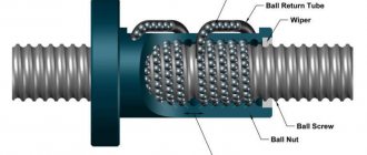
Rack and pinion or rack and pinion
What is a rack and pinion transmission or, in common parlance, “rack and pinion” and what are its main parameters? A rack and pinion transmission is a type of mechanical transmission that converts the rotational motion of a gear into the translational motion of a rack and vice versa. The prototype of this transmission was the rack, with the help of which in the old days cooks hung a pot over the hearth and by rotating the wheel they could adjust the intensity of the fire while cooking.
Then this system smoothly moved to other industries and was already used in railway transport, so the famous “Catalan cremaliers” that pull trains along mountain roads have survived to this day.
Currently, rack and pinion transmissions can be found in various industries from photography to medicine, and in the field of mechanical engineering and machine tools they have occupied their honorable and important niche. Rack and pinion is one of the popular gears for converting rotary motion into linear motion in modern CNC machines.
This popularity is not without reason, because this program has a large number of advantages, such as:
- high reliability of operation in a wide range of loads and speeds
- unlimited stroke length
- high efficiency
- small dimensions
- great resource
- ease of maintenance.
But this type of transmission has several significant disadvantages:
- high requirements for manufacturing precision
- noise of the system due to inaccuracies in the manufacture of the profile and tooth pitch
- high rigidity, which does not compensate for dynamic loads, which often leads to destruction of the transmission.
Let's compare the most common types of gears in axis drives of CNC machines:
| Properties | Ball screw | Rack and pinion transmission | Linear motor |
| Feed force | XX | XXX | X |
| Acceleration | X | XX | XXX |
| Maximum speed | X | XX | XXX |
| Life time | X | XX | XXX |
| Noise level | XXX | XX | X |
| Shock sensitivity | X | X | XXX |
| Investment costs | XX | XXX | X |
X – average indicators XX – optimal combination XXX – best combination
This comparison table is for informational purposes only in maximizing these properties and is not the main criterion for choosing the optimal transmission. So, for example, no matter what the rack and pinion transmission is, it will not be able to approach the maximum speed parameter of a linear motor. And vice versa - in terms of feed force, a linear motor that can create a force close to the maximum force of a rack and pinion drive will be of enormous size or of a special design that is not included in the standard model range of many manufacturers, and, among other things, the use of such a linear motor will probably be economically ineffective. When designing, it is necessary to take into account both the specifics of the equipment and many other factors not included in this table.
The main indicators of rack and pinion transmission for selection are:
- Gear module
- Gear type
- Accuracy and Load
Gear module
The gear module is a universal characteristic that links together its most important parameters such as pitch, tooth height, number of teeth and lug circle diameter. This characteristic is involved in all calculations related to the design of transmission systems. It is numerically selected in such a way that the modulus value coincides with one of the generally accepted values, which can be found in the specialized literature. When designing gears, they usually set the value of this parameter, and from it all the many others can be easily calculated. The initial data for determining the required gear module are strength calculations designed to provide the required power of the mechanical transmission. The gear module can be found in several ways:
m=P/π
where P is the pitch of the gear or rack. This formula can be considered in a different order, as P=mπ, and thus we obtain a direct relationship between the step and the module. Another way is through a gear, knowing the diameter and number of teeth:
m=D/z
And the simplest is to attach an existing transfer element to the template and thereby define a module.
You can obtain a template in 1:1 format by contacting specialists.
Gear type
The tooth profiles of the gear train must ensure a constant transmission ratio. This condition is satisfied by several common profiles: involute, cycloid, circular arc. Of these, the involute profile stands out, providing high strength and durability of wheel teeth, low sliding speeds on the surface of the meshing teeth and high efficiency. It is also easy to manufacture. This engagement is little sensitive to deviations of the interaxial distance, but it allows you to improve the parameters using modification (correction).
There are two most common types of gears used in machine tool construction: spur gears and helical gears. Each type of transmission has its own advantages and disadvantages:
| Spur gears | Helical gears |
Advantages:
Flaws:
| Advantages:
Flaws:
|
What is gear correction?
Correction of involute gearing is the correction of the shape of the involute that forms the tooth in order to improve the strength and other transmission parameters in comparison with the standard one. The correction is carried out to achieve the following goals:
- Designation of the number of gear teeth is less than z<17. When cutting a standard gear with a number of teeth less than 17, the tooth root is undercut, which reduces the bending strength. By appropriate correction, undercutting can be eliminated.
- Increasing the bending strength of the tooth. The teeth of meshing wheels often turn out to be of unequal strength, this may be due to the fact that one of the wheels is steel and the other is bronze or plastic. Another reason for the uneven strength of the wheels may be that the gears have a different number of teeth and therefore they will have different tooth shape coefficients, which are included in the calculation formula for bending. Appropriate correction can make a weaker tooth thicker and thereby increase its bending strength.
The main advantages of correction:
- Increased gear wear resistance. Gear wear depends on the sliding of the teeth during their operation. By correcting the engagement, it is possible to select such areas of the contacting involutes to minimize sliding and thereby increase the wear resistance of the transmission.
- Increased contact strength. Contact strength depends on the radii of curvature of the involutes in the engagement pole. By correcting the gearing, it is possible to select such sections of the involutes so that their radii of curvature are larger than in the standard gearing.
- To fit the gear within a given center distance.
The correction is carried out in several ways, but the most common and often used is the displacement of a standard tool or the so-called height correction, in which the engagement parameters remain unchanged, but the bending strength of the tooth increases and it becomes possible to avoid cutting the tooth.
In the warehouse program gear wheels supplied by our company, as a rule, the correction coefficient is 0. The formula for calculating the center distance between the gear and the rack will be calculated as follows:
Quite often, when designing special equipment and machines, designers use non-standard solutions and layouts. In this case, the drawings sent upon approval before delivery will indicate both the correction factor and the working pitch diameter dw.
The formula for calculating the center distance will be as follows:
Helical cylindrical gears are corrected much less frequently than spur gears, since when working in bending, an oblique tooth is stronger than a straight one. In addition, the specified interaxal distance in helical gearing is achieved by changing the angle of inclination of the teeth (since the most common tooth inclination angle is 19°31ʹ42ʺ, helical gears are equally subject to correction), while in spur gearing this can only be achieved by correction.
Gear accuracy and load
When using even the most advanced methods for manufacturing and assembling gears, manufacturing errors are inevitable, expressed in deviations from the specified dimensions and shape. In gear drives, these errors manifest themselves in deviations of pitch sizes, gaps and the shape of tooth profiles from their theoretical values, non-parallelism of teeth or shaft axes, inaccuracy of the center distance, the occurrence of axial and radial runout of wheels, etc. The consequence of these errors is a disruption of the normal operation of the gear: incomplete fit of mating teeth (small contact patch), the occurrence of additional dynamic loads, vibration, increased noise and, as a result, reduced durability. The influence of errors increases with increasing peripheral speed of the wheels. In this regard, with increasing speed, the requirements for the accuracy of gear manufacturing increase.
The gear racks supplied by our company correspond to the following parameters: Q6 – gear racks made of structural steel C45E with heat treatment in the form of surface hardening, with mounting holes and additional grinding of the teeth; Q8 - gear racks made of structural steel C45E with heat treatment in the form of normalization annealing, with mounting holes, without additional processing of the teeth.
The load characteristics for the maximum load force on a tooth are presented in the graphs below for helical and spur racks.
When designing and calculating the accuracy of CNC machines, you should pay attention to the accuracy class of the gear rack and such a parameter as “step error” (this characteristic is specified in the drawings sent for approval before delivery of the product).
When calculating a rack and pinion transmission for travel lengths of more than 2 meters, the formula for calculating the accuracy of the pitch error of mated racks will be as follows:
where nR is the number of joined slats, Gtf is the slack pitch error, nJ is the number of joints, FJ is the mounting bar error.
Example:
It is necessary to calculate the mechanical error of the gear rack over a travel length of 8 meters (8000 mm) based on the M2 rack, accuracy class Q6, the error of the mounting bar M2H (FJ=0.013).
Option #1. Based on rail HM2L1000-Q6 (L=1000 mm):
E=(8×0.034)+(7×0.013)=0.363 mm
Option #2. Based on the HM2L2000-Q6 rail (L=2000 mm):
E=(4×0.038)+(3×0.013)=0.191 mm
The accuracy of the system when using two-meter slats is almost 2 times better than when using meter slats with a large number of joints. It is recommended that the joining of both spur and helical racks of any accuracy class and module be performed using a special mounting plate.
promptly supplies racks and gears from 1 to 12 modules, accuracy classes from Q4 to Q10. The range includes special versions for the chemical and medical industries (anti-corrosion version). Accuracies for Q6 and Q8 in the most common sizes and gear types are available in stock. At the customer's request, it is possible to supply non-standard racks and gears with a larger module and different accuracy classes.
View availability and buy gear racks in Moscow, St. Petersburg, Yekaterinburg
View availability and buy gears in Moscow, St. Petersburg, Yekaterinburg
Articles
06 Nov 2020
Advantages and disadvantages
Assemblies with racks are considered obsolete and cumbersome. In fact, a rack and pinion mechanical transmission is a gear engagement of a small gear with a segment of a wheel having an infinitely large diameter. The ideal mechanism has not yet been invented and the gear has to be selected taking into account its technical characteristics.
Flaws
The transmission has a number of disadvantages, these include the following:
- outdated technology;
- large backlash;
- loud noise;
- low accuracy of movements;
- large error at the junction of the rails;
- requires high manufacturing precision;
- manual assembly;
- afraid of dirt;
- low productivity;
- limited range of applications.
The unit has all the disadvantages of gears. The main one is the destruction of teeth due to overload. On belt drives, when the cutting load increases, the belt slips along the pulley. Teeth don't have this option. By analogy, fingers are inserted into safety clutches and torque is transmitted through them. When overloaded, they are destroyed and replaced with new ones.
The difference is that making a stud with a landing diameter is much simpler and cheaper. Gears are made of alloy steel. The process of their manufacture is complex, multi-stage. The part is expensive.
The manufacturing accuracy of a rack is higher than that of a gear. The stronger the bend of the tooth base line, the greater the error when cutting it.
The mechanical interaction of two parts is always accompanied by noise. It is partially reduced by lubrication. Helical and multi-row gears operate smoothly and quietly.
If there is no gap along the involute, then the parts will “stick together” at the molecular level. Such an experiment was carried out at the end of the last century. The designers created a gear pair with ideal dimensions and cleanliness. As a result, having made several revolutions, the gears were welded and it was impossible to disconnect them.
The gap is needed to compensate for the expansion of the metal when heated. Any friction is accompanied by an increase in temperature.
The accuracy of movement does not allow performing various operations completely automatically. On older equipment there is additional fine tuning. CNC machines are equipped with electronic coordinate control, which, through a control unit, performs precise coordinate adjustment.
When joining slats, special templates are used, and the tooth pitch error is minimized to an acceptable size. The assembly of rack and pinion gears in most cases remains manual; numerous adjustments and adjustments cannot be automated. The exception is units without large loads with small movements, such as in a car.
CALCULATION OF RACK TRANSMISSIONS FOR STRENGTH
Formulas (4.1)-(4.2) for calculating cylindrical gears cannot be applied to rack and pinion gears (z2 = ¥; i12 = z1/z2 = 1/u = 0). For design calculations based on contact stresses, the manual [7, p. 107] provides a formula that allows you to determine the initial (pitch) diameter of the rack and pinion gear (mm):
dw1 , (8.1)
where σНР – permissible contact stress, MPa (see [7, pp. 89-91]) or
clause 3.1;
Fx – axial force on the rack, N;
KN – load factor [7, p. 92-97];
y in
d – auxiliary parameter;
y in
d =
in
/dw1 = 0.4-0.8, where
in
is the width of the rack (the width of the gear rim
in
1 "
in
+ (5-10) mm).
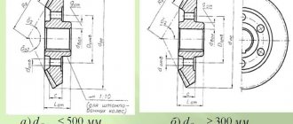
With a moving rack
(Fig. 8.1, a) in the design task they usually indicate the axial force on the rack Fx and the translational speed v2, equal to the peripheral speed of the gear v1;
| v01 |
with a stationary rack
(Fig. 8.1, b) – speed v01 of the translational movement of the center O1 of the gear and force Fx. When performing calculations, the following dependencies can be used: Fx = 2Т1/dw1; P = Fx×v2 = T1×w1 and v1 = 0.5 ×w × dw1 (Fig. 8.1, a); P = Fx×v01 = T1×w1 and v01 = 0.5 ×w1 × dw1 (Fig. 8.1, b). In the given formulas: Fx in H; T1 in N×m; R in W; v2, v01 in m/s; w in rad/s; dw1 in m (see paragraphs 1.5-1.8).
| b |
| A |
| Fx = Ft1 |
Rice. 8.1. Rack and pinion transmission
The approximate value of the module m¢ is found from the calculated dw1 and the selected number of teeth z1, taking dw1 = d1 at x=0. Then m¢ » dw1/z1, where m¢ and dw1 are in mm. When choosing z1, it is necessary to ensure the condition z1 ³ zmin, where zmin is the minimum number of teeth at which there is no cutting of the teeth. The value of zmin depends on x, , β. For unbiased spur gears (x1=0, =1, α = 20°) zmin ≈ 17, and for helical gears zmin ≈ 17·cos3β, where β = 8-18° is the angle of inclination of the tooth line. More complete information on the choice of zmin, as well as the displacement coefficients xmin and xmax, at which there is no cutting or sharpening of the teeth in the gear, is given in paragraph 4.1.8 and in [12, p. 25-26].
The previously obtained m' and dw1 are clarified if it is necessary to change z1, ψbd or σНР. Then the value m' is determined from the calculation of the teeth for bending:
,
where KF is the load factor [7, p. 93-97];
σFP – permissible bending stress, MPa (see [7, pp. 89-91] or clause 3.3).
Of the m' values found using formulas (8.1-8.2), the largest is taken and rounded to the standard value (clause 4.1.7). Taking into account the accepted z1, m, β, dw1 is found (Table 4.5), as well as other basic geometric parameters and tolerances of the rack and pinion transmission [12, p. 73-77, 189-193; 24, p. 558-568]. For elements of the rack drawing, see Fig. 8.2.
Rice. 8.2. straight toothed rack