The universal dividing head UDG-250 makes it possible to perform various milling, hobbing, boring, drilling, marking and other work related to rotating a part at a given angle
Basic equipment of the dividing head: universal dividing head assembled, rear headstock, three-jaw self-centering chuck, adapter flange to the self-centering three-jaw chuck, thrust center, driver, bolts for the machine groove, technical description and operating instructions for universal dividing heads, passport of the universal dividing head, passport of a three-jaw chuck.
The dividing head UDG-250 (UDG-D-250) makes it possible to perform various milling, hobbing, boring, drilling, marking and other work related to rotating a part at a given angle.
Parts can be processed using the UDG-250 dividing head in centers, in a chuck or on a spindle mandrel.
Using the universal dividing head UDG-250, you can perform the following operations:
- direct division of circles by a multiple of 24, i.e. on 2, 3, 4, 6, 8, 12, 24
- simple division of circles into a number of parts from 2 to 400 and into some numbers over 400
- differential division of circles into a number of parts from 43 to 400 without intervals
- milling of spirals with pitches from 25 to 400 mm
- gear milling
- setting the axis of the workpiece at the required angle relative to the machine table
- various works on milling machines related to dividing a circle into unequal parts in degrees, cutting spirals, etc.
UDG-D-250 (UDG-D-250A) List of dividing head accessories
- Lunette 1 piece
- Guitar for differential division 1 piece
- Guitar for spiral cutting 1 piece
- Mandrel for differential division 1 pc.
- Gear wheels:
- z=25; m=1.5 2 pcs
- z=30; m=1.5 1 piece
- z=35; m=1.5 1 piece
- z=40; m=1.5 1 piece
- z=50; m=1.5 1 piece
- z=55; m=1.5 1 piece
- z=60; m=1.5 1 piece
- z=70; m=1.5 1 piece
- z=80; m=1.5 1 piece
- z=90; m=1.5 1 piece
- z=100; m=1.5 1 piece
UDG-D-250 Dividing head design
The UDG-D-250 dividing head has a cast iron base 16 with tie rods 17, on which a housing 18 is installed. By loosening the nuts 19 (Fig. 3), you can rotate the housing to a certain angle. The rotation angle is measured using the scale and vernier 20 (see Fig. 2).
On the supporting plane of the base of the dividing head there are two keys that are precisely fitted parallel to the spindle, which are used to install the head in the groove of the milling machine table. The housing contains a spindle with a through hole. The ends of the spindle are bored to a Morse taper. A center 21 is installed at one end, and a mandrel 13 (see Fig. 1) for differential division is installed at the other. The front end of the spindle has a thread and a centering belt 22 (see Fig. 2) for installing and fastening a flange with a self-centering chuck or a driver. On the spindle collar there is a dial 9 of direct division, which has twenty-four holes.
On the spindle, in its middle part, sits a worm wheel with a circular groove at the end, into which the end of a clamp 23 mounted in the housing 18 fits. The worm wheel receives rotation from a worm located in an eccentric sleeve. The worm can be engaged or disengaged by turning the eccentric sleeve using handle 24 (see Fig. 3) with sector 25.
The dividing disk is mounted on a shaft mounted in sliding bearings in cover 26 (see Fig. 2). The cover is fixed on the body 18 with a centering bore and is fixedly attached to the base.
Bevel and cylindrical gears are installed on the shaft of the dividing disk, as well as a drive bar that has a handle with a lock that moves along the required row of holes on the dividing disk. A sliding sector 27, consisting of rulers 28 and a clamping screw 29, is pressed to the dividing disk using a spring, with the help of which the rulers are installed at the required angle. The spring washer prevents spontaneous rotation of the sector.
The mechanical drive shaft 30 from the machine is mounted in plain bearings and located in a sleeve 31 with a flange. The sleeve is attached to cover 26. At the end of the shaft there is a bevel gear, which is in constant mesh with the bevel gear sitting on the shaft of the dividing disk. The dividing disk is fixed in the required position with stopper 7.
Tailstock
The tailstock serves to support the second end of the workpiece when installing it in the centers or chuck of the dividing head. The center of the headstock can be moved in horizontal and vertical directions. At the base 32 there is a housing 33, which is connected to the rail by a pin. By rotating the head of the gear shaft, the housing can be raised, lowered and rotated relative to the axis of the pin. In the required position, the tailstock is secured to the machine table using bolts and nuts.
The movement of the quill 34 with the half-center 35 is carried out by rotation of the handwheel 36 mounted on the screw.
On the supporting plane of the base there are two guide keys, aligned with the axis of the quill; The keys ensure that the centers of the dividing head and the tailstock coincide when they are installed on the machine table.
Lunette
The steady rest is an additional support when processing long and thin parts. In its body 37 there is a screw that moves with the help of a nut 38. The screw has a prismatic head 39; with the help of a locking screw 40 the head can be secured at the required height.
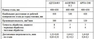
Main characteristics and markings
The main parameter of the equipment is its gear ratio, the inverse value of the gear ratio of the worm pair in the structure. The designation of the device indicates its type, gear ratio and maximum diameter of the workpiece being processed. Thus, UDG-40-D320 means: a universal head with a gear ratio of 40 and a maximum diameter of the workpiece of 320 mm. A simplified designation without a gear ratio is often used, for example UDG-320.
The main parameters of the head are:
- Maximum workpiece diameter.
- Height of rigging centers.
- The angle of rotation of the spindle from the horizontal position down and up from the center line.
- The gear ratio of the pair determines the number of revolutions of the handle when setting for a full revolution of the disk.
- Heaviest load.
- Dimensions.
You should also take into account the diameter of the mounting flange for connection to the machine spindle, the number of the Morse cone for fastening in the spindle hole and other passport data.
To ensure the required processing accuracy, pay attention to the parameters specified in the device passport:
- radial runout of the spindle cone (at the base and at a distance of 300 mm from the front);
- Diameter runout;
- deviation of the axis of the supporting surface from a right angle, etc.
List of controls for the dividing head UDG-250
- Handle with lock. Fixing the dividing disk
- Stopper. Locking the dividing disk
- Latch. Fixing the direct division dial
- Screw. Fastening the head housing to the base
- Clamp Spindle lock
- Lever. Turning the worm on and off
- Sliding sector. Counting holes on the dividing disk
- Handwheel. Moving the tailstock quill
- Screw. Sector fastening
- Screw. Leash attachment
- Screw. Attaching the indexing disc clamp assembly
- Shank. Guitar mount
- Screw. Tailstock quill fastening
- Gear head. Moving the tailstock vertically
- Bolt. Tailstock housing mount
- Screw. Fastening the bar with handle and lock
UDG-250 Lubrication points of the universal dividing head
- I - Disc shaft and bevel gear. Lubricate daily
- II - Cylindrical and bevel gears. Pouring 100 g of oil through the lid
- III - Front spindle bearing. Lubricate daily
- IV - Worm pair. Pouring 200 g of oil into the housing
- V - Rear spindle bearing. Lubricate daily
- VI - Quill and tailstock screw. Lubrication every two days
- VII - Dividing head drive shaft. Lubrication every two days
UDG-250 Kinematic diagram of the universal dividing head
In simple division, rotation of the spindle 1 is transmitted from the handle 2 with a lock through a pair of spur gears 3, a worm 4 and a worm wheel 5 located in the middle part of the spindle. In this case, the dividing disk 6 must be secured using the stopper 7, and the clamp 8 of the direct division dial 9 is turned off.
In differential division, the angle of rotation of the spindle is determined by the amount of rotation of the handle with the lock relative to the dividing disk and the amount of rotation of the disk itself, which receives rotation from the spindle through the replaceable gears 10 of the guitar 11 and a pair of bevel gears 12. To transmit rotation from the spindle to the replaceable gears of the guitar, a mandrel 13 is used, on the cylindrical neck of which a replaceable gear 14 is installed. In this case, the dividing disk must be released from the stopper, and the direct division dial lock must be turned off.
When cutting a spiral, the spindle receives rotation from the lead screw of the milling machine through the replaceable gears of the guitar, a pair of bevel gears 12, an intermediate shaft 15, cylindrical gears 3, a worm 4 and a worm wheel 5. In this case, the dividing disk must be released from the stopper, and the dial clamp must be directly division is turned off.
1) Height of centers, mm.
25, 30, 35, 40, 50, 55, 60, 70, 80, 90, 100
DIVISION HEAD DEVICE
The universal dividing head (Fig. 1) consists of a worm pair and a number of gears. The housing 1 is mounted on the base 2 with its axles and is secured to it with cap clamps 3 to prevent rotation. A spindle 4 rotates in the bearings of the housing, on which a winding disk 5 is attached for direct counting of the rotation of the spindle, a worm wheel 6 and a locking wheel 7.
At the front end of the spindle, next to the front disk, chucks are installed to secure the workpieces.
Rotation of the workpiece at a certain angle is carried out by rotating the handle 8 with a spring lock 9, which fixes the handle relative to the dividing disk 10. From the handle 8, rotation through the roller 11 is transmitted by gears 12 and 13. The latter is connected to a shaft 14, made integral with the falling worm 15 The worm 15 is engaged with the worm wheel 6 by rotating the eccentric 16, which lifts the worm box 17.
Rice. 1 Dividing head device
METHODS OF DIVISION
The universal dividing head allows you to rotate the workpiece at a certain angle in various ways:
Direct division of the circle into 2, 3, 4, 6, 8, 12 and 24 parts;
Simple division of a circle into a number of parts from 2 to 2160 at intervals;
Differential division of a circle into a number of parts from 43 to 400 without intervals.
3.1. DIRECT DIVISION
The circle is directly divided into parts of 180, 120, 90, 60, 45, 30 and 15º or into 2, 3, 4, 6, 8, 12 and 24 parts in cases where great accuracy is not required.
For direct division, it is necessary to unlock the spindle, disengage the worm 15 from the worm wheel 6 by rotating the eccentric 16 counterclockwise (Fig. 1). The spindle with the workpiece is rotated manually using the chuck, and the angle of rotation is measured using the winding disk 5, which has a circular scale (360 divisions) graduated in degrees.
For accurate reading of the rotation angle there is a vernier 18, which allows you to count with an accuracy of up to 5 minutes.
The angle of rotation of the workpieces is determined from the relationship:
Operating procedure
Direct division
Direct division is used when dividing a circle into 2, 3, 4, b, 8, 12 and 24 parts in cases where great accuracy is not required.
When dividing directly, you must:
- disengage the worm from engagement with the worm wheel by turning handle 24 (see Fig. 3) until it stops
- release the direct division dial clamp from engagement
The spindle is turned by hand by rotating the workpiece or chuck. The angle of rotation is measured using a degree scale marked on the direct division dial and a line on the front spindle bushing.
Secure the spindle in the required position using clamp 23 (see Fig. 2).
When dividing into parts or faces, the calculation is made using the formula
N = 360°/a(1)
where n is the number of parts or faces; A
a is the spindle rotation angle.
Simple division
A simple division of a circle into equal and unequal parts is carried out with a stationary dividing disk using a handle with a lock. The amount of rotation of the handle is measured by the holes on the dividing disk and is fixed with a locking rod.
Differential division
Dividing a circle into a number of parts greater than 42, not a multiple of the number of holes on the dividing disk, can be done by a differential method, the essence of which is that the angle of rotation of the spindle is determined by the amount of rotation of the handle with the lock relative to the dividing disk and the amount of rotation of the disk receiving rotation from the spindle through replacement guitar gears.
The guitar is mounted on a cylindrical shank on which it can be rotated and secured in the desired position. To install replacement gears, the guitar is equipped with movable pins and adapter bushings. To transmit rotation to the replaceable gears, a mandrel is inserted into the rear cone of the spindle, onto the cylindrical neck of which the replaceable gear is installed.
Before starting work, turn the handle to check the smooth rotation of all installed gears.
When performing differential division, the indexing disk stop must be turned off.
The adjustment procedure for differential division is the same as for simple division.
Differential division is only possible with the spindle in a horizontal position.
Features of the design and device of the dividing head
- • The angle when turning can be either fixed (same) or variable (different) - at the choice of the operator, for optimal positioning accuracy.
- • The workpiece is secured in the chuck. If it is too long, a tailstock should be used to ensure proper contact, but not deviate from the original base.
- • Putting this device into operation is advisable only in cases where it is more difficult or impossible to carry out any work without it.
- • It is permissible to orient the device to sequentially solve several problems - cutting grooves, cavities and teeth, boring polyhedra, and so on.